Advertisement
Quick Links
PHOTOCELLS
EN
12/24V DC
V3
Ref. 114359
CONTENTS OF THE KIT
x 1
x 6
x 6
x 4
A - SAFETY INSTRUCTIONS
A1 - OPERATING PRECAUTIONS
• Read this entire manual before starting the installation.
• Do not allow children to operate the product.
A2 - SERVICING AND CLEANING
• Use a soft, slightly damp cloth to clean your product.
• All electrical connections must be performed with the power switched
off (safety switch in OFF position) and battery disconnected.
• Do not use abrasive or corrosive substances.
• Do not spray any products directly onto the unit.
• In winter, scrape off the frost which may have formed on the lenses.
A3 - RECYCLING
This logo denotes that devices which are no longer in use
must not be disposed of as household waste. They are likely
to contain hazardous substances that are dangerous to both
health and the environment. Return the equipment to your
local distributor or use the recycling collection service
provided by your local council.
Pour en savoir plus :
www.quefairedemesdechets.fr
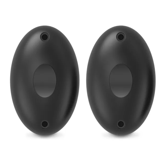
B - PRODUCT DESCRIPTION
B1 - PHOTOCELLS
3
1
2
1
Reception photocell RX
2
Transmission photocell TX
3
Lens of the infrared beam
C - INSTALLATION
C1 - SET OF PHOTOCELLS
• Read the label on the back to identify the transmission photocell (TX) and
the reception photocell (RX)
• Install the reception photocell (RX is indicated on the back) on the side
with the control box or the motor containing the electronic control board.
The surface of the posts must be perfectly flat in order to properly align
the infrared beam of the photocells.
• Place the photocells at exactly the same height from the ground; they
must be perfectly aligned and parallel to each other.
The distance between the outer side of the gate and the photocells must
be between 10cm and 15cm.
• Mount the photocells on the posts.
30cm min
60cm max
Outer side of the property
10cm min
15cm max
precise alignment
view from above
Inner side of the property
Take note: place a silicone seal between the pillar and the photocells
as well as at the output of the power cable.
Take care not to put silicone on the base of the photocell to avoid
condensation of the product.
20mm
Outer side of the property
C2 - SET OF PHOTOCELLS
When used with a non-visible gate, it is mandatory to
install a second set of photocells to prevent the
gate from opening when an object (a car, person, etc.) is behind the gate.
• The photocells must be perfectly aligned and parallel to each other.
• The reception photocells (RX indicated at the back) must be installed at
the same side of the gate as the electronic control box.
• The photocells must be installed on the inner side of the property. The
distance between the main edges of the gate in an open position at 90°
and the photocells must be between 10cm and 15cm maximum.
• The mounts used to secure the photocells must be correctly secured to
the ground and precisely aligned.
• The photocells must be placed exactly at the same height from the
ground, and the height must be between 30cm and 60cm.
pair 1
RX1
90°
90°
10cm min / 15cm max
RX2
pair 2
Inner side of the property
View from above
30cm min
60cm max
D - CONNECTIONS
The photocells are connected differently depending on the type of motor
specification:
- For the electric operation of sliding gates, see section D1
- For the electric operation of swing gates, see section D2
Disconnect the removable terminal block, connect the photocell wires to
the terminal block as shown in the diagram below and then reconnect the
terminal block.
D1 - CONNECTION FOR THE ELECTRIC OPERATION OF
SLIDING GATES
• 1 set of photocells
By connecting the photocells in this way, the system reacts to a break of the
infrared beam only during closing.
M1
Reception
photocell
~-
~-
~+
NO COM NC
RX1
• 2 sets of photocells
By connecting the photocells in this way, the system reacts to a break of
one or the other infrared beams only during closing.
M1
TX1
Reception
photocell RX1
~-
~+
NO COM NC
~-
Reception pho-
tocell RX2
~-
~+
NO COM NC
~-
TX2
Transmission
photocell
~+
TX1
Transmission
photocell TX1
~+
Transmission
photocell TX2
~+
Advertisement

Related Manuals for Avidsen 114359


Summary of Contents for Avidsen 114359
- Page 1 B1 - PHOTOCELLS 20mm PHOTOCELLS 12/24V DC 30cm min 60cm max Ref. 114359 D - CONNECTIONS The photocells are connected differently depending on the type of motor specification: - For the electric operation of sliding gates, see section D1 Reception photocell RX...
- Page 2 0 892 701 369 0,35 € / min Monday to Friday, 9AM to 12PM and 2PM to 6PM CET. Avidsen undertakes to keep a stock of spare parts for this product throughout the contractual warranty period. F3 - EU DECLARATION OF CONFORMITY...
Need help?
Do you have a question about the 114359 and is the answer not in the manual?
Questions and answers