
Related Manuals for STIEBEL ELTRON IS E


Summary of Contents for STIEBEL ELTRON IS E
- Page 1 Service Manual IS_E / IS_E-2 Author: Mr. Apiwat Limrueangwattanakul Date: 25 March 2013 Revision: version 1.0...
-
Page 2: Table Of Contents
Table of Contents Warning ................................3 General product information ......................... 4 Technical data ..............................5 Wiring Diagram .............................. 6 Troubleshooting ............................. 7 Root clause analysis ............................9 Heating Elements checking ........................ 9 TRIAC checking ..........................10 Flow Switch checking ........................11 PCB Control checking ........................ -
Page 3: Warning
Warning Warning: This service manual is suitable for qualified Technicians only. Warning: Disconnect power supply before open cover. -
Page 4: General Product Information
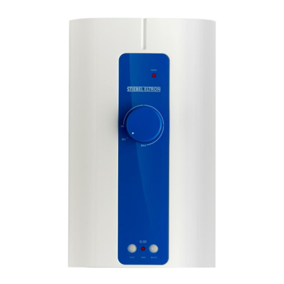
General product information The Stiebel Eltron IS pressureless (open) instantaneous water heater is a device for heating water for shower. The electrical power is electronically controlled. The unit switches the power on once the flow volume reach 1.5-2 l/min. The “Power” light (C) indicates that the unit is switched on. If the temperature adjustment rotary (B) switch is turned to the left, it is possible to take a cold shower (the heating will not be switched on). -
Page 5: Technical Data
Technical Data Model IS 35E/E-2 IS 45E/E-2 IS 60E/E-2 Type Opened outlet Water pressure 0 Mpa (0 bar) Water connection G 1/2" (external thread) Electrical connection 1/N/PE ~ 220…240V 220 V 230 V 240 V Recommended cable size Sqmm. Recommended circuit breaker Min flow rate to active unit (L/min) 1.3 ±... -
Page 6: Wiring Diagram
Wiring Diagram Type IS...E / IS…E-2 A = Heating element B = Electronic control set C = ELSD Circuit D= Single Triac Set E = Thermal cut - out (TCO) F = Button Board G = Current Leakage Sensor Type IS… A = Heating element B = Electronic control set D = Single Triac Set... -
Page 7: Troubleshooting
Troubles shooting Problem & Condition Cause Correction Power lamp not "ON" - No power supply to unit - Check breaker and water not hot - Check connecting - Power line not tight points and fix. - ELSD cut-off - ELSD reset - Check Triac set - Thermal cut-out (TCO) - Check Reed switch... - Page 8 Troubles shooting Problem & Condition Cause Correction ELSD cut-off - Overloaded current on main - Turn off other appliance breaker - Power line wrong connection - Reconnect power line Power on maximum but - Water over flow - Reduce water flow water not hot enough Water temperature - Irregular water flow...
-
Page 9: Root Clause Analysis
Root clause analysis 1. Heating Elements checking Definition: Heating Element is a metal coil that heats up to high temperatures, when electricity is applied. To check the Heating Element, follow the steps below: - Disconnect cables from the Elements. - Set Multi meter to Ohm range "Ω" or " )))) "and check as show in the pictures. ... -
Page 10: Triac Checking
2. TRIAC Checking Definition: The Triac is a three-terminal device, which controls and conducts current flow during both alternations of an AC cycle. To check Single Triac, follow the steps below: - Disconnect cables and unplug any connectors in red circle. - Set Multimeter to Ohm range "Ω"... -
Page 11: Flow Switch Checking
3. Flow switch checking Definition: Flow switch (Reed sw.) is a vacuum tube with two thin metallic strips at open circuit (NO) configuration while on standby. It activates or goes on close circuit by use of a magnet. Below you will find two different ways to check the flow switch. 3.1) Option 1: Set unit at vertical direction -Set Multi meter to Ohm range "Ω"... - Page 12 3.2) Option 2: Set unit to upside down (turn 180 ˚) direction. - Set Multi meter to Ohm range "Ω" or " )) " and unplug the reed switch connector from the printed circuit board (PCB) and check Reed Switch as in the pictures. Pole - Pole Down Check...
-
Page 13: Pcb Control Checking
4. PCB control checking Visual check Check Result Cause Action Electronic equipment is burned Short circuit Change new PCB Visual Damage is not visible PCB failed Change new PCB... -
Page 14: Thermostat Checking
5. Thermostat checking Automatic Reset Thermostat Definition: The thermostat will automatically cut out power system when the water in tank rises to 45 5 o he the thermostat, follow the steps below: -Disconnect cables as in the picture. - Set multimeter to Ohm range "Ω" or " )))) - Check on poles. -
Page 15: System Comfirm
6. System confirm Ensure that you have tightened all the screws back into their original positions. This final test must be performed after repairing the unit. If all steps below are working correctly the unit can be returned to the end user. 1.
Need help?
Do you have a question about the IS E and is the answer not in the manual?
Questions and answers