Table of Contents
Advertisement
Quick Links
Installation, Commissioning, Operating and
Unit 4, Station Road, Bakewell, Derbyshire DE45 1GE United Kingdom
www.codel.co.uk
t : +44 (0) 1629 814 351
© 2010 CODEL International Ltd.
Maintenance Manual
For EnergyTech 301 and EnergyTech 302
Triboelectric Dust Air Quality Monitors
Issue: A | Revision: 9 | Date: 15/10/21 | Reference: 100246
CODEL International Ltd.
f : +44 (0) 8700 566 307
300 Series
e : codel@codel.co.uk
300
CODEL
web : www.codel.co.uk
Page: 1
Advertisement
Table of Contents

Summary of Contents for Forbes Marshall CODEL EnergyTech 300 Series
- Page 1 300 Series Installation, Commissioning, Operating and Maintenance Manual For EnergyTech 301 and EnergyTech 302 Triboelectric Dust Air Quality Monitors Issue: A | Revision: 9 | Date: 15/10/21 | Reference: 100246 CODEL International Ltd. CODEL Unit 4, Station Road, Bakewell, Derbyshire DE45 1GE United Kingdom www.codel.co.uk t : +44 (0) 1629 814 351 f : +44 (0) 8700 566 307...
- Page 2 Section 1 The EnergyTech 300 Series CODEL A Forbes Marshall Company Issue: A | Revision: 9 | Date: 15/10/21 | Reference: 100246 Page: 2...
- Page 3 CODEL International Ltd is a UK company based in the heart of the Peak District National Park at Bakewell, Derbyshire. The company specialises in the design and manufacture of high-technology instrumentation for the monitoring of combustion processes and atmospheric pollutant emissions. The constant search for new products and existing product improvement keeps CODEL one step ahead.
- Page 4 Section 1 The EnergyTech 300 Series CODEL A Forbes Marshall Company Issue: A | Revision: 9 | Date: 15/10/21 | Reference: 100246 Page: 4...
-
Page 5: Table Of Contents
Contents Contents THE ENERGYTECH 300 SERIES ............................9 ....................10 ONTINUOUS NDICATIVE ARTICULATE ONITORING SPECIFICATION .................................. 11 ................................11 EASUREMENTS ..................................11 UTPUTS ............................12 LECTRONICS ENCLOSURE ................................12 NTRUSIVE ROBE ) ............................. 12 ABLING IF SUPPLIED BY ODEL PRINCIPLES OF OPERATION ............................13 DESCRIPTION .................................. - Page 6 APPENDIX-3: MEMORY MAP ............................42 1.27 ..................................42 ENERAL 1.28 COMMS RAM ................................43 1.29 COMMS EEPROM ..............................53 1.30 ................................ 69 OMMANDS 1.31 ......................................69 CODEL A Forbes Marshall Company Issue: A | Revision: 9 | Date: 15/10/21 | Reference: 100246 Page: 6...
- Page 7 IMPORTANT The warning signs (and meanings) shown below, are used throughout these instructions and are intended to ensure your safety while carrying out installation, operation and maintenance procedures. Please read these instructions fully before proceeding. WARNING! Caution, risk of danger or damage. WARNING! Caution, risk of electric shock.
- Page 8 Section 1 The EnergyTech 300 Series CODEL A Forbes Marshall Company Issue: A | Revision: 9 | Date: 15/10/21 | Reference: 100246 Page: 8...
-
Page 9: The Energytech 300 Series
The EnergyTech 300 Series The EnergyTech 301 and 302 are low-cost dust monitors using well-proven technology providing accurate and rapid results. Being adaptable it can can be used on duct sizes from 250mm to 5m making the EnergyTech 301 a suitable sensor for a wide range of applications where a dust measurement is required A low cost dust monitor using well-proven technology providing accurate and rapid results. -
Page 10: Continuous Indicative Particulate Monitoring
If emissions are required to be quantified in mg/m on a continuous basis, then please contact Codel for advice. CODEL A Forbes Marshall Company Issue: A | Revision: 9 | Date: 15/10/21 | Reference: 100246 Page: 10... -
Page 11: Specification
Specification Measurements Operating principle Tribo Electric Measurement units mg/m Temperature range, Flue: C to +200 Temperature range, Ambient: C to +55 Measurement range 0 – 100% / 0.00 - 6500mg/m (Dependent upon Transfer Factor) Particle size range 0.1 to 100µm Gain 1 –... -
Page 12: Electronics Enclosure
WARNING! if the cable length is greater than 1km it is recommended to use cable spec 0.75mm2~24/0.2. If unsure, please contact Codel. CODEL A Forbes Marshall Company Issue: A | Revision: 9 | Date: 15/10/21 | Reference: 100246 Page: 12... -
Page 13: Principles Of Operation
Principles of Operation When a particle moving in a duct collides with (or passes near) a probe that is grounded to earth, a transfer of charge takes place from the particle to the conductor. This is known as tribo-electricity or frictional electrification and results in a charge being imparted to the probe. -
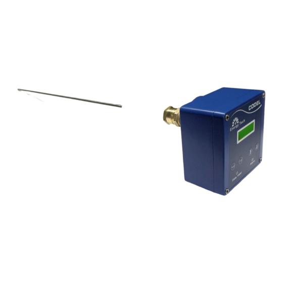
Page 14: Description
Mounting Boss Sensor Head Probe Figure 1: Energy Tech 301 – Full system Insulation Sheath CODEL A Forbes Marshall Company Issue: A | Revision: 9 | Date: 15/10/21 | Reference: 100246 Page: 14... -
Page 15: Power Supply (Et302 Only)
Power Supply (ET302 only) The EnergyTech 302 requires a PSU to convert the mains (90-263V AC) supply to the 24V DC required by the analyser. A Codel 24V DC PSU can be optionally provided to power an EnergyTech 302. Mains Input 24V DC Connection Earthing bolt... -
Page 16: Installation
If the dust level display is required to be viewed regularly to confirm acceptable • levels, if possible, install the Energy Tech 301 where the display can be easily seen by plant operators CODEL A Forbes Marshall Company Issue: A | Revision: 9 | Date: 15/10/21 | Reference: 100246 Page: 16... - Page 17 Avoid mounting Energy Tech 301 on a vertical duct that vents to atmosphere as it may be affected by rain ingress. Figure 3 : Energy Tech 301 - Preferred Locations Figure 4 : Energy Tech 301 - Mounting Strategies Alternative CODEL www.codel.co.uk ©...
-
Page 18: Installing The Mounting Stub
If the stack wall is thin gauge and will not weld easily or will not bear the weight of the probe, follow the method below. CODEL A Forbes Marshall Company Issue: A | Revision: 9 | Date: 15/10/21 | Reference: 100246 Page: 18... -
Page 19: Thin- Walled Stacks
1.10 Thin- Walled Stacks Manufacture a stub as described above. Prepare the mounting plate shown in Figure 5. Cut a hole Ø28mm (1 /8 ins) at the centre and drill for large pop rivets or self-tapping screws. Bend the plate to the curvature of the stack and weld the stub to the plate as outlined above. -
Page 20: Mounting The Sensor
Optional Extra Junction Box EnergyTech 302: 24V DC Customer 24V DC In: monitoring system Figure 8: ET302 System Schematic Optional Extra Junction Box CODEL A Forbes Marshall Company Issue: A | Revision: 9 | Date: 15/10/21 | Reference: 100246 Page: 20... -
Page 21: Wiring The Mains Connector
1.12 Wiring the Mains Connector WARNING! This task should be only be undertaken by qualified personnel, familiar with site safety regulations. While connecting the cores of the mains cable to the connector, ensure that the cable is disconnected from the power source. -
Page 22: Output Connector
4-20Ma Out Analogue 0V N/C Alarm Contact N/O Alarm Contact Alarm Common 24V Output RS485 4-20Ma Out Analogue 0V Alarm Outputs +24V CODEL A Forbes Marshall Company Issue: A | Revision: 9 | Date: 15/10/21 | Reference: 100246 Page: 22... -
Page 23: Optional - Rs485 Looped With Output Connection, For Maintenance Only
NOTE By default, the EnergyTech 300 series output type is set to 24V (unless otherwise requested). To configure the analyser to produce a volt free output follow the procedure outlined in section 5.7.1 on the following page. Optional – RS485 looped with output connection, for maintenance only. - Page 24 Section 5 Installation CODEL A Forbes Marshall Company Issue: A | Revision: 9 | Date: 15/10/21 | Reference: 100246 Page: 24...
-
Page 25: Wiring To Power Pcb Connectors
1.14 Wiring to Power PCB connectors A wiring diagram is shown below in Figure 11 & Figure 12 for reference purposes only. These connections are normally made at the factory. 1.14.1 EnergyTech 301 Figure 11: ET301 Wiring Diagram 1.14.2 EnergyTech 302 Figure 12: ET302 Wiring Diagram Figure 135: ET302 Wiring Diagram CODEL... -
Page 26: Commissioning
The system will now enter initialising, this process will last 30 seconds. Few seconds later the measurement screen appears. Wait for data valid LED (green) to come on. • CODEL A Forbes Marshall Company Issue: A | Revision: 9 | Date: 15/10/21 | Reference: 100246 Page: 26... -
Page 27: Zero Calibration
In normal working conditions, the data valid LED will come on when the power-up time has elapsed. NOTE During the Commissioning of the device, it is required that the user enters the “Setup Mode” menu, which is password protected. This PassCode will be prompted each time the user enters the Setup Mode Menu. the Default PassCode is 0000. -
Page 28: Insitu Span Calibration (Hardware Gain Setting)
NOTE The system should now read the target levels. CODEL A Forbes Marshall Company Issue: A | Revision: 9 | Date: 15/10/21 | Reference: 100246 Page: 28... -
Page 29: Transfer Factor (Dust Factor)
1.17 Transfer factor (Dust Factor) NOTE The values and menu choices below are for example only, and/or are default values. When completing the commissioning process, fill these fields to the user’s specification based upon the relevant calculations. Main Menu Sum menu 1 Sub menu 2 Setup Mode Signal... -
Page 30: Cf_C (Offset Factor)
To set up the offset factor, perform the following steps: Enter the menu path: Setup Mode → Signal → CF_c Press key to begin entering the CF_c value. • CODEL A Forbes Marshall Company Issue: A | Revision: 9 | Date: 15/10/21 | Reference: 100246 Page: 30... - Page 31 to increase or decrease the current digit between 0 and 9 • (0.000 - 9999). Press to set the current digit and proceed to the next, finalising and setting • the value when pressed over the last digit. CODEL www.codel.co.uk ©...
-
Page 32: Analogue (Ma) Output Configuration
Exit Set the mA Output Unit to the customer specification and press enter to open the • Set Output Unit menu option. CODEL A Forbes Marshall Company Issue: A | Revision: 9 | Date: 15/10/21 | Reference: 100246 Page: 32... - Page 33 Use the arrow keys to scroll through the available units and the enter key to select • and set. The available units are: mg/m3 mg/Nm3 Span - The mA span value is also set from the “mA Output” submenu of the Setup •...
-
Page 34: Contact Output
Use the arrow keys to scroll through the available units and the enter key to select • and set. The available units are: mg/m3 mg/Nm3 CODEL A Forbes Marshall Company Issue: A | Revision: 9 | Date: 15/10/21 | Reference: 100246 Page: 34... - Page 35 Direction - The relay system allows the user to configure if the relay channel is set to normally open or normally closed. This option is useful in fail-safe environments where power outages are common, forcing the connected relays to switch in case of power failure.
-
Page 36: Damping
If the final digit is selected when the enter key is pressed the value is set and the • user returned to the previous menu tier. CODEL A Forbes Marshall Company Issue: A | Revision: 9 | Date: 15/10/21 | Reference: 100246 Page: 36... -
Page 37: Maintenance
Maintenance HOT SURFACE! Heat may be conducted from the process duct to the enclosure and care should be taken when maintenance work is required, to ensure that suitable protective gloves are worn before handling. Remember also that the probe may also be hot and should be allowed to cool before cleaning. 1.22 Cleaning Interval The primary maintenance task associated with Energy Tech 301 is cleaning the... -
Page 38: Serious Instrument Failure
Codel is proud of its quick ‘turn-around’ time on servicing these units and acknowledges that the Energy Tech 301 needs to be returned as quickly as possible to continue its important work. CODEL A Forbes Marshall Company Issue: A | Revision: 9 | Date: 15/10/21 | Reference: 100246 Page: 38... -
Page 39: Standard Modbus Communication With Codel Modbus
Appendix 1 1.25 Standard MODBUS Communication with CODEL MODBUS Summary; Using standard MODBUS protocol, function 03 allows a host to obtain the contents of one or more holding registers in the CODEL MODBUS. The request frame from the host (typically a DCS or SCADA) defines the relative address of the first holding register followed by the total number of consecutive registers to be read. -
Page 40: Slave Response (From Codel Modbus Scu)
Standard baud rate 9600 Bits per byte 1 start bit 8 data bits (least significant sent first) 1 stop bit no parity CODEL A Forbes Marshall Company Issue: A | Revision: 9 | Date: 15/10/21 | Reference: 100246 Page: 40... -
Page 41: Modbus List
1.26 MODBUS List Y Value Inst (Long) Y Value Smoothed (Long) Z Value Inst (Long) Z Value Smoothed (Long) Meas Percent Raw Meas Percent Inst Meas Percent Smoothed Meas Percent (*100) Meas mg m3 (*10) Meas mg Nm3 (*10) ModeStatus PerformanceStatus CommandStatus FaultStatus... -
Page 42: Appendix 2 - Revision & Amendment Register
ISSUE DATE REVISION DETAILS NUMBER NUMBER Appendix 3 Menu Map, rev 20211014 added 15/10/21 Whole doc Updated to newest ops manual format CODEL A Forbes Marshall Company Issue: A | Revision: 9 | Date: 15/10/21 | Reference: 100246 Page: 42... -
Page 43: Appendix-3: Memory Map
Appendix-3: Memory Map General RAM - COMMS EEPROM - COMMS RAM Size 0x0200 EEPROM Size 0x0200 RAM Offset 0x0000 EEPROM Offset 0x2000 RAM Read Min 0x0000 EEPROM Read Min 0x2000 RAM Read Max 0x01FF EEPROM Read Max 0x21FF RAM Write Min 0x0000 EEPROM Write Min 0x2040... -
Page 44: Comms Ram
COMMS RAM Modbus Address Modbus Register Local Name Codel Address Data Type Notes Multiplier 0x0000 40001 0x0001 0x0002 40002 0x0003 0x0004 40003 0x0005 0x0006 40004 0x0007 0x0008 40005 0x0009 0x000A 40006 0x000B 0x000C 40007 0x000D Command Flag Low 0x000E 40008 Command Flag High 0x000F 0x0010... - Page 45 Modbus Address Modbus Register Local Name Codel Address Data Type Notes Multiplier 0x0108 40133 Meas mg m3 Copy 0x0109 0x010A 40134 Meas mg Nm3 Copy 0x010B 0x010C 40135 0x010D 0x010E 40136 0x010F 0x0110 40137 Meas mg m3 Sec 0x0111 0x0112 40138 Meas mg Nm3 Sec 0x0113...
- Page 46 Modbus Address Modbus Register Local Name Codel Address Data Type Notes Multiplier 0x0125 Probe Signal DTx Detector Level Inst 0x0126 40148 Long 0x0127 0x0128 40149 Probe Signal DTx 0x0129 Detector Level 0x012A Smoothed Long 40150 0x012B 0x012C 40151 0x012D 0x012E 40152 0x012F 0x0130...
- Page 47 Modbus Address Modbus Register Local Name Codel Address Data Type Notes Multiplier 0x0143 0x0144 40163 0x0145 Probe Signal Delta Y long 0x0146 40164 0x0147 0x0148 40165 0x0149 0x014A 40166 0x014B 0x014C 40167 0x014D 0x014E 40168 0x014F 0x0150 40169 0x0151 Probe Signal Y Value Inst Long 0x0152 40170...
- Page 48 Modbus Address Modbus Register Local Name Codel Address Data Type Notes Multiplier 0x0160 Pre-Zero Cal Delay 40177 0.001 Counter 0x0161 0x0162 Zero Cal Delay 40178 0.01 Counter 0x0163 0x0164 Post Zero Cal Delay 40179 0.001 Counter 0x0165 0x0166 Pre-Span Cal Delay 40180 0.001 Counter...
- Page 49 Modbus Address Modbus Register Local Name Codel Address Data Type Notes Multiplier 0x017E 40192 0x017F 0x0180 External PCB 40193 Temperature 0x0181 0x0182 40194 Pressure 0x0183 0x0184 40195 Ambient Temperature 0x0185 0x0186 40196 0x0187 0x0188 40197 Flue Gas Temperature 0x0189 0x018A 40198 0x018B 0x018C...
- Page 50 Modbus Address Modbus Register Local Name Codel Address Data Type Notes Multiplier Probe Signal DTx 0x019B Distortion Ratio 0x019C 40207 0x019D 0x019E 40208 0x019F 0x01A0 Probe Signal DRx 40209 Detector Level Raw 0x01A1 0x01A2 Probe Signal DRx 40210 Detector Level Inst 0x01A3 Probe Signal DRx 0x01A4...
- Page 51 Modbus Address Modbus Register Local Name Codel Address Data Type Notes Multiplier Probe Signal ADC 0x01B7 Count Abs 0x01B8 Probe Signal Signal 40221 Amplitude 0x01B9 0x01BA 40222 0x01BB 0x01BC 40223 0x01BD 0x01BE 40224 0x01BF 0x01C0 40225 0x01C1 0x01C2 40226 0x01C3 0x01C4 40227 0x01C5...
- Page 52 Modbus Address Modbus Register Local Name Codel Address Data Type Notes Multiplier 0x01D4 40235 Probe Signal DRx 0x01D5 Detector Level 0x01D6 Smoothed Long Copy 40236 0x01D7 0x01D8 40237 0x01D9 Probe Signal Set Cal Inst long Copy 0x01DA 40238 0x01DB 0x01DC 40239 0x01DD Probe Signal Delta Y...
- Page 53 Modbus Address Modbus Register Local Name Codel Address Data Type Notes Multiplier 0x01F2 Probe Signal 40250 Concentration Inst 0x01F3 Probe Signal 0x01F4 40251 Concentration 0x01F5 Smoothed 0x01F6 40252 Meas Percent 0x01F7 0x01F8 40253 Meas mg m3 0x01F9 0x01FA 40254 Meas mg Nm3 0x01FB EnergyTech301 Mode 0x01FC...
-
Page 54: Comms Eeprom
COMMS EEPROM Modbus Address Modbus Register Local Name Codel Address Data Type Notes Multiplier 0x2000 44097 4096 0x2001 0x2002 44098 4097 0x2003 0x2004 44099 4098 0x2005 0x2006 44100 4099 0x2007 Instrument Name Instrument Name 0x2008 44101 4100 0x2009 0x200A 44102 4101 0x200B 0x200C... - Page 55 Modbus Address Modbus Register Local Name Codel Address Data Type Notes Multiplier 0x201B 0x201C 44111 4110 0x201D 0x201E 44112 4111 0x201F 0x2020 44113 4112 0x2021 0x2022 44114 4113 0x2023 0x2024 44115 4114 0x2025 0x2026 44116 4115 0x2027 Build Number Build Number 0x2028 44117 4116...
- Page 56 Modbus Address Modbus Register Local Name Codel Address Data Type Notes Multiplier 0x2038 44125 4124 Serial Number 0x2039 0x203A 44126 4125 0x203B 0x203C 44127 4126 0x203D 0x203E RW Target EEPROM 44128 4127 AbsLocation 0x203F Communications Protocol: 0x0000) Comms Protocol 0x2040 Codel 0x0001) 44129 4128...
- Page 57 Modbus Address Modbus Register Local Name Codel Address Data Type Notes Multiplier 0x2051 Probe Signal DRx 0x2052 Software Gain Divider 44138 4137 Probe Signal DRx Software Gain 0x2053 Multiplier 0x2054 44139 4138 0x2055 0x2056 44140 4139 0x2057 0x2058 44141 4140 0x2059 0x205A 44142...
- Page 58 Modbus Address Modbus Register Local Name Codel Address Data Type Notes Multiplier 0x206C Probe Signal DRx High 44151 4150 Threshold 0x206D 0x206E Probe Signal DRx Low 44152 4151 Threshold 0x206F 0x2070 44153 4152 Relay Selection 0x2071 0x2072 44154 4153 Span Voltage Divider 0x2073 0x2074 44155...
- Page 59 Modbus Address Modbus Register Local Name Codel Address Data Type Notes Multiplier 0x2088 Probe Signal ADC DRx 44165 4164 Threshold 0x2089 0x208A Probe Signal ADC DRx 44166 4165 Saturation 0x208B 0x208C Probe Signal ADC DRx 44167 4166 Low Threshold 0x208D 0x208E Probe Signal ADC DRx 44168...
- Page 60 Modbus Address Modbus Register Local Name Codel Address Data Type Notes Multiplier 0x20A4 44179 4178 0x20A5 0x20A6 44180 4179 0x20A7 0x20A8 44181 4180 0x20A9 0x20AA 44182 4181 0x20AB 0x20AC 44183 4182 0x20AD 0x20AE 44184 4183 0x20AF 0x20B0 InSitu Span Calibration 44185 4184 PID Controller...
- Page 61 Modbus Address Modbus Register Local Name Codel Address Data Type Notes Multiplier Zero DC Offset PID 0x20C1 Controller Tolerance 0x20C2 Zero DC Offset PID 44194 4193 Controller Setpoint 0x20C3 0x20C4 Zero DC Offset PID 44195 4194 Controller Min 0x20C5 0x20C6 Zero DC Offset PID 44196 4195...
- Page 62 Modbus Address Modbus Register Local Name Codel Address Data Type Notes Multiplier 0x2108 Span Calibration ADC 44229 4228 Count 0x2109 0x210A Span Calibrate 44230 4229 Percentage 0x210B 0x210C 44231 4230 0x210D 0x2126 44244 4243 0x2127 0x2128 PCB Temperature Low 44245 4244 Threshold 0x2129...
- Page 63 Modbus Address Modbus Register Local Name Codel Address Data Type Notes Multiplier 0x213E 44256 4255 0x213F 0x2140 Probe Signal Span 44257 4256 0.001 Factor A Coefficient 0x2141 0x2142 Probe Signal Span 44258 4257 Factor B Coefficient 0x2143 0x2144 44259 4258 0x2145 0x2146 44260...
- Page 64 Modbus Address Modbus Register Local Name Codel Address Data Type Notes Multiplier Probe Signal 0x215A 44270 4269 ScaleShape A 0.0000001 0x215B Coefficient Probe Signal 0x215C 44271 4270 ScaleShape B 0.00001 0x215D Coefficient Probe Signal 0x215E 44272 4271 ScaleShape C 0x215F Coefficient 0x2160 44273...
- Page 65 Modbus Address Modbus Register Local Name Codel Address Data Type Notes Multiplier 0x2176 44284 4283 0x2177 0x2178 44285 4284 0x2179 0x217A 44286 4285 0x217B 0x217C 44287 4286 0x217D 0x217E 44288 4287 0x217F 0x2180 mA1 Absolute 44289 4288 Location 0x2181 mA1 Type 0x2182 44290 4289...
- Page 66 Modbus Address Modbus Register Local Name Codel Address Data Type Notes Multiplier mA2 Type 0x2192 44298 4297 mA2 Data Validity 0x2193 mA2 Smoothing 0x2194 Coefficient 44299 4298 0x2195 mA2 Span 0x2196 44300 4299 0x2197 mA2 Zero 0x2198 44301 4300 0x2199 Alarm2 Absolute Location 0x219A...
- Page 67 Modbus Address Modbus Register Local Name Codel Address Data Type Notes Multiplier Ambient Temperature 0x21AC C Control Flag 44311 4310 0x21AD Flue Gas Temperature 0x21AE C Control Flag 44312 4311 0x21AF 0x21B0 Pre-Zero Calibration 44313 4312 Delay 0x21B1 0x21B2 Post Zero Calibration 44314 4313 Delay...
- Page 68 Modbus Address Modbus Register Local Name Codel Address Data Type Notes Multiplier 0x21C8 44325 4324 0x21C9 0x21CA 44326 4325 0x21CB 0x21CC 44327 4326 0x21CD 0x21CE 44328 4327 0x21CF 0x21D0 44329 4328 0x21D1 0x21D2 44330 4329 0x21D3 0x21D4 44331 4330 0x21D5 0x21D6 44332 4331...
-
Page 69: Commands List
Modbus Address Modbus Register Local Name Codel Address Data Type Notes Multiplier 0x21E6 44340 4339 0x21E7 0x21E8 44341 4340 0x21E9 0x21EA 44342 4341 0x21EB 0x21EC 44343 4342 0x21ED 0x21EE 44344 4343 0x21EF Time hundredth of 0x21F0 Seconds Alarm 44345 4344 Time Seconds Alarm 0x21F1 Time Minutes Alarm... - Page 70 High RAM: 0x0E Low RAM: 0x0F Maintenance Start 0x21 Maintenance Normal Running 0x02 Maintenance Stop 0x22 Maintenance Test Mode 0x03 Clear Performance Status 0x04 InSitu Span Calibrate 0x0A Bias Current Zero Calibrate 0x11 Zero Calibration 0x10 EEPROM Initialisation 0x23 Start Detector Level Simulation 0x34 Stop Detector Level Simulation 0x35...
Need help?
Do you have a question about the CODEL EnergyTech 300 Series and is the answer not in the manual?
Questions and answers