Table of Contents
Advertisement
Quick Links
取扱いおよび設置説明書
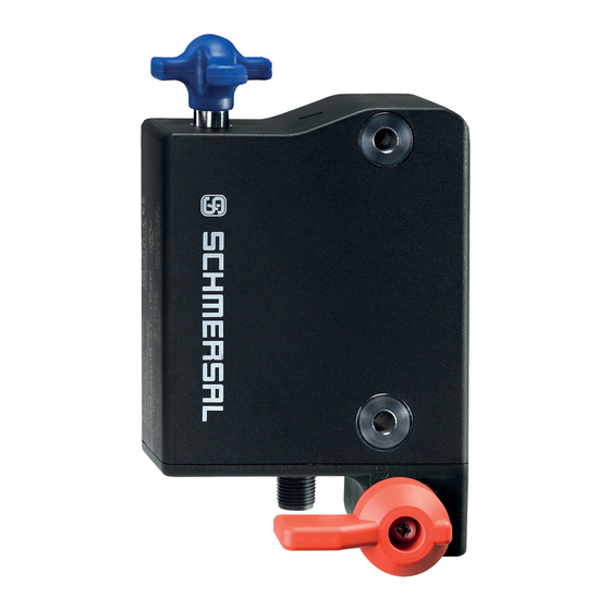
AZM300Z-ST-SD2P-T-DU
1 About this document
1.1 Function
This document provides all the information you need for the mounting, set-up and commissioning to ensure the safe
operation and disassembly of the switchgear. The operating instructions enclosed with the device must always be
kept in a legible condition and accessible.
1.2 Target group of the operating instructions: authorised qualified
personnel
All operations described in the operating instructions manual must be carried out by trained specialist personnel,
authorised by the plant operator only.
Please make sure that you have read and understood these operating instructions and that you know all applicable
legislations regarding occupational safety and accident prevention prior to installation and putting the component
into operation.
The machine builder must carefully select the harmonised standards to be complied with as well as other technical
specifications for the selection, mounting and integration of the components.
The information contained in this operating instructions manual is provided without liability and is subject to
technical modifications.
1.3 Explanation of the symbols used
Information, hint, note: This symbol is used for identifying useful additional information.
F
2
Caution:Failure to comply with this warning notice could lead to failures or malfunctions.
Warning:Failure to comply with this warning notice could lead to physical injury and/or damage to the machine.
1.4 Appropriate use
Products in Schmersal's range are not intended to be used by private end consumers.
Advertisement
Table of Contents

Subscribe to Our Youtube Channel
Related Manuals for schmersal AZM300Z-ST-SD2P-T-DU


Summary of Contents for schmersal AZM300Z-ST-SD2P-T-DU
- Page 1 Caution:Failure to comply with this warning notice could lead to failures or malfunctions. Warning:Failure to comply with this warning notice could lead to physical injury and/or damage to the machine. 1.4 Appropriate use Products in Schmersal's range are not intended to be used by private end consumers.
-
Page 2: General Safety Instructions
The user must observe the safety instructions in this operating instructions manual, the country specific installation standards as well as all prevailing safety regulations and accident prevention rules. Further technical information can be found in the Schmersal catalogues or in the online catalogue on the Internet: products.schmersal.com. -
Page 3: Special Versions
SD2P シリアル診断出力及び2 PNP安全出力 なし スプリングロック マグネットロック なし 手動解除 緊急解除 緊急脱出 2.2 Special versions For special versions, which are not listed in the ordering code, these specifications apply accordingly, provided that they correspond to the standard version. 2.3 Purpose The non-contact, electronic safety switchgear is designed for application in safety circuits and is used for monitoring the position and locking of movable safety guards. -
Page 4: Warning About Misuse
The user must evaluate and design the safety chain in accordance with the relevant standards and the required safety level. If multiple safety sensors are involved in the same safety function, the PFH values of the individual components must be added. The entire concept of the control system, in which the safety component is integrated, must be validated to the relevant standards. - Page 5 ハウジング 材質 樹脂、グラスファイバー強化熱可塑性樹脂、自己消火性 総重量 650 g 準備時間、最大 5,000 ms リスク持続時間、最大 200 ms アクチュエーターの応答時間、最大 100 ms 入力の応答時間、最大 1.5 ms 一般データ - 仕様 スプリングロック ガードロック監視 シリアル診断 ラッチング 緊急脱出 短絡検出 短絡監視 直列接続 安全機能 一体型システム診断、状態 フェイルセーフデジタル出力の数 安全性評価 規格 EN ISO 13849-1 EN IEC 61508 安全性評価...
- Page 6 ロック時引抜強度, 最大 1,500 N Latching force, adjustable, position 1 25 N Latching force, adjustable, position 2 50 N Type of the fixing screws 2x M6 Tightening torque of the fixing screws, minimum 6 Nm Tightening torque of the fixing screws, maximum 7 Nm Mechanical data - Switching distances according EN IEC 60947-5-3 確実な切替距離「ON」...
- Page 7 環境条件 - 絶縁値 定格絶縁電圧 32 VDC 定格インパルス耐電圧 0.8 kV Overvoltage category IEC/EN 60664-1に準拠した汚染度 電気的データ 動作電圧、最小 20.4 VDC 動作電圧、最大 26.4 VDC Note (Power supply, general) stabilised PELV power supply No-load supply current I , maximum 100 mA Current consumption with magnet ON, average 200 mA Current consumption with magnet ON, peak 350 mA / 200 ms...
- Page 8 Electrical data - Safety digital outputs Designation, Safety outputs Y1 and Y2 安全出力 short-circuit proof, p-type Voltage drop U , maximum Leakage current I , maximum 0.5 mA Voltage, Utilisation category DC-12 24 VDC Current, Utilisation category DC-12 0.25 A Voltage, Utilisation category DC-13 24 VDC Current, Utilisation category DC-13...
-
Page 9: General Mounting Instructions
This device complies with the nerve stimulation limits (ISED SPR-002) when operated at a minimum distance of 100 mm. Changes or adjustments not expressly approved by K.A. Schmersal GmbH & Co. KG could void the user's authority to operate the equipment. - Page 10 For the correct fixing of the solenoid interlock and the actuator, two mounting holes for M6 screws are provided (tightening torque: 6 … 7 Nm). Any mounting position. The system must only be operated with an angle of ≤ 2° between the solenoid interlock and the actuator.
- Page 11 The diagrams show a closed guard system with a set latching force of 50 N (see also chapter "adjustment of latching force"). Provide for a sufficient insertion of the actuator into the rotary handle. Correct False To avoid any interference inherent to this kind of system and any reduction of the switching distances, please observe the following guidelines: The presence of metal chips in the vicinity of the solenoid interlock is liable to modify the switching distance Keep away from metal chips...
-
Page 12: Manual Release
Minimum distance between two solenoid interlocks as well as other systems with same frequency (125 kHz) The minimum distance from metallic securing surfaces to the face side "A" and underside "B" of the device is 5 mm. 3.2 Manual release For the machine set-up, the solenoid interlock can be unlocked in a de-energised condition. - Page 13 Caution: do not turn beyond the end stop! A: connector plug M12, 8-pole B: LED display C1: Manual release by means of slotted screwdriver C2: Manual release by means of triangular key TK-M5 The manual release must be protected against accidental actuation, e.g. by using the enclosed seal after completing commissioning.
-
Page 14: Mounting With Mounting Plate
Reset of the manual release by actuating the red emergency exit lever must be prevented by the user. Emergency exit (-T/-T8) (fitting and actuation only from within the hazardous area) To activate the emergency exit, turn the red lever in the direction of the arrow to the end stop. The safety outputs switch off and the guard system can be opened. - Page 15 3.5 Dimensions All measurements in mm. AZM300...-T/-T8 and -N Device with emergency exit or emergency release Emergency exit -T / Emergency release -N Emergency exit -T8...
-
Page 16: Actuator And Accessories
3.6 Actuator and accessories Actuator AZ/AZM300-B1 (not included in delivery) Mounting plate MP-AZ/AZM300-1 (available as accessory) MS-AZ/AZM300-B1-1 (available as accessory) Aluminium protective plate as a cover for use on glass and plastic doors on machines with high design requirements... - Page 17 Lockout tag SZ 200-1 (available as accessory) Bowden cable release ACC-AZM300-BOW-.-.M-.M (available as accessory) Observe the additional notes in the operating instructions of the Bowden cable release.
-
Page 18: General Information For Electrical Connection
The safety-monitoring module does not need to have a cross-wire short monitoring function, if necessary, the cross-wire short monitoring function must be disabled. Information for the selection of suitable safety-monitoring modules can be found in the Schmersal catalogues or in the online catalogue on the Internet: products.schmersal.com. - Page 19 Series-wiring can be set up. In the case of a series connection, the risk time remains unchanged and the reaction time increases by the sum of the reaction time of the inputs per additional unit specified in the technical data. The quantity of devices is only limited by the cable drops and the external cable fuse protection, according to the technical data.
-
Page 20: Wiring Configuration And Connector Accessories
4.4 Wiring configuration and connector accessories Function safety switchgear Pin configuration of Colour codes of the Poss. colour code of other the connector Schmersal commercially available connectors connectors according to EN 60947-5-2 With conventional With serial IP67 / IP69 ... - Page 21 5 Actuator coding and latching force adjustment 5.1 Actuator coding Solenoid interlocks with standard coding are ready to use upon delivery. Individually coded solenoid interlocks and actuators will require the following "teach-in" procedure: 1. Switch the solenoid interlock's voltage supply off and back on. 2.
- Page 22 6.1 Magnet control In the power to unlock version of the AZM300, the solenoid interlock is unlocked when the IN signal (= 24V) is set. In the power to lock version of the AZM300, the solenoid interlock is locked when the IN signal (= 24 V) is set. 6.2 Mode of operation of the safety outputs In the standard AZM300Z variant, the unlocking of the solenoid interlock causes the safety outputs to be disabled.
- Page 23 Fault warning A fault that does not immediately endanger the safety function of the safety switchgear (e.g. too high ambient temperature, safety output at external potential, cross-circuit) leads to delayed shutdown (see Table 2). This signal combination, diagnostic output disabled and safety channels still enabled, can be used to stop the production process in a controlled manner.
- Page 24 Power to unlock: IN = 0 = Lock Safety guard can be locked Safety guard locked Power to lock: IN = 1 = Lock Safety guard can be locked Safety guard locked Table 1: Diagnostic information of the safety switchgear Safety outputs Y1, Diagnostic Magnet control IN...
-
Page 25: Solenoid Interlock With Serial Diagnostic Function Sd
Table 1: Diagnostic information of the safety switchgear Diagnostic Magnet control IN Safety outputs Y1,Y2 output OUT System condition Power to Power to green yellow AZM300Z AZM300B unlock lock Error warning 24 V Flashes 24 V 24 V Error 0 V (24 V) 24 V (0 V) Flashes... - Page 26 In this way, the diagnostic signals can be evaluated by means of a PLC. The necessary software for the integration of the SD-Gateway is available for download at products.schmersal.com. The response data and the diagnostic data are automatically and permanently written in an input byte of the PLC for each solenoid interlock in the series-wired chain.
-
Page 27: Set-Up And Maintenance
Table 3: I/O data and diagnostic data (The described condition is reached, when Bit = 1) Bit n° Call Byte Response-Byte Diagnostic error warning Diagnostic error The leading diagnosis message through bit 1 indicates whether locking or unlocking of the guard system is possible. The solenoid interlock cannot be unlocked if e.g. - Page 28 The safety switchgear must be disposed of in an appropriate manner in accordance with the national prescriptions and legislations.
Need help?
Do you have a question about the AZM300Z-ST-SD2P-T-DU and is the answer not in the manual?
Questions and answers