Table of Contents
Advertisement
Advertisement
Table of Contents

Related Manuals for MSI 945GCM5 Series


Summary of Contents for MSI 945GCM5 Series
- Page 1 945GM5/ 945GCM5/ 945GZM5 Series MS-7267 (V4.X) Mainboard G52-72671XD...
-
Page 2: Copyright Notice
If a problem arises with your system and no solution can be obtained from the user’s manual, please contact your place of purchase or local distributor. Alternatively, please try the following help resources for further guidance. Visit the MSI website for FAQ, technical guide, BIOS updates, driver updates, and other information: faq/esc_faq_list.php Contact our technical staff at: support@msi.com.tw... -
Page 3: Safety Instructions
Safety Instructions Always read the safety instructions carefully. Keep this User’s Manual for future reference. Keep this equipment away from humidity. Lay this equipment on a reliable flat surface before setting it up. The openings on the enclosure are for air convection hence protects the equip- ment from overheating. -
Page 4: Fcc-B Radio Frequency Interference Statement
FCC-B Radio Frequency Interference Statement T h is eq uip men t h as been tested and found to c omply with the limits for a Class B digital device, pursuant to Part 15 of the FCC Rules. These limits are designed to provide reasonable protection against harmful interference in a residential installation. - Page 5 WEEE (Waste Electrical and Electronic Equipment) Statement...
-
Page 8: Table Of Contents
Chapter 1. Getting Started ... 1-1 Mainboard Specifications ... 1-2 Mainboard Layout ... 1-4 Packing Checklist ... 1-5 MSI Special Feature ... 1-6 Chapter 2. Hardware Setup ... 2-1 Quick Components Guide ... 2-2 CPU (Central Processing Unit) ... 2-3 Introduction to LGA 775 CPU ... - Page 9 Slots ... 2-20 PCI Express Slots ... 2-20 PCI (Peripheral Component Interconnect) Slots ... 2-20 PCI Interrupt Request Routing ... 2-21 Chapter 3. BIOS Setup ... 3-1 Entering Setup ... 3-2 Control Keys ... 3-3 Getting Help ... 3-3 General Help <F1> ... 3-3 The Main Menu ...
-
Page 10: Chapter 1. Getting Started
Getting Started Chapter 1 Getting Started Thank you for c hoosing the 945G M 5/ 945G CM 5/ 945GZM5 Series (MS-7267 v4.X) Micro-ATX mainboard. The 945GM5/ 945GCM5/ 945GZM5 Series mainboard is based on Intel 945G/ 945GC/ 945GZ and Intel ® ®... -
Page 11: Mainboard Specifications
® M emory Support - DDRII 400/ 533/ 667 SDRAM (4 GB Max, for 945GM5 series) - DDRII 400/ 533 SDRAM (2 GB Max, for 945GCM5/ 945GZM5 series) - 2 DDRII DIMMs (240pin / 1.8V) LAN (optional) - Supports 10/100/1000 Fast Ethermet by Realtek 8111B... - Page 12 - 2 USB 2.0 pinheaders - 1 SPDIF-out pinheader (for HDMI Graphic card only) Slots - 1 PCI Express x16 slot(for 945GM5/ 945GCM5 series only) - 1 PCI Express x1 slot - 2 PCI slots (Support 3.3V/ 5V PCI bus Interface) Form Factor - Micro-ATX (24.5cm X 22.0 cm)
-
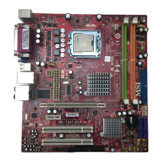
Page 13: Mainboard Layout
T:RS-Out M:CS-Out B:SS-Out PCI_E1 (For 945GM5/ 945GCMG series only) LAN Chip PCI _E2 PCI2 Codec PCI1 JAUD1 945GM5/ 945GCM5/ 945GZM5 (MS-7267 V4.X) Series Micro-ATX Mainboard CPUFA N1 JCOM1 Intel 945G/ GC/ GZ CD_IN1 J SPD1 FDD 2 SYSFAN1 PW RFAN1... -
Page 14: Packing Checklist
Getting Started Packing Checklist MSI Driver/Utility CD SATA Cable (optional) MSI motherboard Standard Cable for Back IO Shield Power Cable IDE Devices (optional) User’s Guide * The pictures are for reference only and may vary from the packing contents of the... -
Page 15: Msi Special Feature
M S-7267 M ainboard MSI Special Feature Core Center The Core Center is a new utility you can find in the CD-ROM disk. The utility is just like your PC doctor that can detect, view and adjust the PC hardware and system status during real time operation. - Page 16 Getting Started Left-wing: Current system status In the left sub-menu, you can configure the settings of FSB, Vcore, Memory Voltage and AGP Voltage by clicking the radio button next to each item and make it available (the radio button will be lighted as yellow when selected), use the “+” and “-” buttons to adjust, then click “OK”...
-
Page 17: Chapter 2. Hardware Setup
Hardware Setup Chapter 2 Hardware Setup This chapter provides you with the information about hardware setup procedures. While doing the installation, be careful in holding the components and follow the installation procedures. For some components, if you install in the wrong orientation, the components will not work properly. -
Page 18: Quick Components Guide
M S-7267 M ainboard Quick Components Guide PWRCONN1, p.2-9 ATX1, p.2-9 JCI2, p2-14 Back Panel, p.2-10 PCIE_X16, p.2-20 PCI 1~3, p.2-21 JAUD1, p.2-16 DIMM1/2, p.2-7 CPU, p.2-3 CPUFAN1, p2-14 JCOM1, p.2-18 CD_IN1, FD D 2 , p.2-15 p.2-12 JSPD1, p.2-16 JBAT1, p.2-19 I DE 1 , p.2-12... -
Page 19: Cpu (Central Processing Unit)
CPU socket called LGA775. When you are installing the CPU, make sure to install the cooler to prevent overheating. If you do not have the CPU cooler, contact your dealer to purchase and install them before turning on the computer. For the latest information about CPU, please visit http://www.msi.com.tw/program/ products/mainboard/mbd/pro_mbd_cpu_support.php Important 1. -
Page 20: Cpu & Cooler Installation
M S-7267 M ainboard CPU & Cooler Installation W hen you are installing the CPU, make sure the CPU has a cooler attached on the top to prevent overheating. If you do not have the cooler, contact your dealer to purchase and install them before turning on the computer. Meanwhile, do not forget to apply some silicon heat transfer compound on CPU before installing the heat sink/ cooler fan for better heat dispersion. - Page 21 5. Lift the load lever up and open the load plate. 7. Visually ins pect if the CPU is seated well into the socket. If not, take out the CPU with pure vertical motion and reinstall. Hardware Setup 6. After confirming the CPU direction for correct mating, put down the CPU in the socket housing frame.
- Page 22 M S-7267 M ainboard 9. Press down the load lever lightly onto the load plate, and then se- cure the lever with the hook under retention tab. 11. Press the four hooks down to fas- ten the cooler. Then rotate the lock- ing switch (refer to the correct di- rection marked on it) to lock the hooks.
-
Page 23: Memory
Memory The mainboard provides two 240-pin non-ECC DIMMs and supports dual-channel technology up to 2GB system memory. For more information on compatible components, please visit http://www.msi.com.tw/ program/products/mainboard/mbd/pro_mbd_trp_list.php DDRII 240-pin, 1.8V 56x2=112 pin Dual-Channel: Channel A in GREEN; Channel B in ORANGE Dual-Channel Memory Population Rules Dual-Channel mode can enhance the performance of the system. -
Page 24: Installing Ddr2 Modules
M S-7267 M ainboard Installing DDR2 Modules 1. The memory module has only one notch on the center and will only fit in the right orientation. 2. Insert the DIMM memory module vertically into the DIMM slot. Then push it in until the golden finger on the memory module is deeply inserted in the socket. -
Page 25: Power Supply
Power Supply ATX 24-Pin Power Connector: ATX1 This connector allows you to connect an ATX 24-pin power supply. To connect the ATX 24-pin power supply, make sure the plug of the power supply is inserted in the proper orientation and the pins are aligned. -
Page 26: Back Panel
M S-7267 M ainboard Back Panel Parallel M ou se Keyboard Serial Port M ouse/Keyboard Connector ® The standard PS/2 mouse/keyboard DIN connector is for a PS/2 Parallel Port Connector A parallel port is a standard printer port that supports Enhanced Parallel Port (EPP) and Extended Capabilities Parallel Port (ECP) mode. - Page 27 Audio Port Connectors These audio connectors are used for audio devices. You can differentiate the color of the audio jacks for different audio sound effects. Green audio jack - Line Out, is a connector for speakers or headphones. Blue audio jack - Line In, is used for external CD player, tapeplayer or Pink audio jack - Mic In, is a connector for microphones.
-
Page 28: Connectors
M S-7267 M ainboard Connectors Floppy Disk Drive Connector: FDD2 This standard FDD connector supports 360K, 720K, 1.2M, 1.44M and 2.88M floppy disk types. FDD2 Hard Disk Connector: IDE1 The mainboard provides a one-channel Ultra ATA 100 bus Master IDE controller that supports PIO mode 0~4, Bus Master, and Ultra DMA 66/100 function. -
Page 29: Serial Ata Connectors: Sata1~Sata4
Serial ATA Connectors: SATA1~SATA4 SATA1~SATA4 are high-speed Serial ATA interface ports. Each supports serial ATA data rates of 300MB/s. Both connectors are fully compliant with Serial ATA 2.0 specifications. Each Serial ATA connector can connect to 1 hard disk device. Serial ATAII cable Connect to SATA connector Important... -
Page 30: Fan Power Connectors: Cpufan1, Sysfan1&Pwrfan1
M S-7267 M ainboard Fan Power Connectors: CPUFAN1, SYSFAN1 & PWRFAN1 The fan power connectors support system cooling fan with +12V. W hen connecting the wire to the connectors, always take note that the red wire is the positive and should be connected to the +12V, the black wire is Ground and should be connected to GND. -
Page 31: Cd-In Connector: Cd_In1
CD-In Connector: CD_IN1 This connector is provided for CD-ROM audio. Front Panel Connectors: JFP1/JFP2 The mainboard provides two front panel connectors for electrical connection to the front panel switches and LEDs. The JFP1 is compliant with Intel Connectivity Design Guide. JFP1 Power Switch... -
Page 32: Front Panel Audio Connector: Jaud1
M S-7267 M ainboard Front Panel Audio Connector: JAUD1 The JAUD1 front panel audio connector allows you to connect the front panel audio ® and is compliant with Intel Front Panel I/O Connectivity Design Guide. SIGNAL PORT 1L PORT 1R PRESENCE# PORT 2R SENSE1_RETIRN... -
Page 33: Front Usb Connectors: Jusb1/ Jusb2
Front USB Connectors: JUSB1/ JUSB2 The mainboard provides two USB 2.0 pinheaders (optional USB 2.0 bracket available) that are compliant with Intel increases data transfer rate up to a maximum throughput of 480Mbps, which is 40 times faster than USB 1.1, and is ideal for connecting high-speed USB interface peripherals such as USB HDD, digital cameras, M P3 players, printers, mo- dems and the like. -
Page 34: Serial Port Connector: Jcom1 (Optional)
M S-7267 M ainboard Serial Port Connector: JCOM1 (optional) The mainboard provides one 9-pin header as serial port. The port is a 16550A high speed communication port that sends/receives 16 bytes FIFOs. You can attach a serial mouse or other serial devices directly to it. JCOM1 2-18 Pin Definition... -
Page 35: Jumpers
Jumpers Clear CMOS Jumper: JBAT1 There is a CMOS RAM onboard that has a power supply from external battery to keep the data of system configuration. With the CMOS RAM, the system can automatically boot OS every time it is turned on. If you want to clear the system configuration, set the JBAT1 (Clear CMOS Jumper ) to clear data. -
Page 36: Slots
Meanwhile, read the documentation for the expansion card to configure any necessary hardware or software settings for the expansion card, such as jumpers, switches or BIOS configuration. 2-20 PCI Express x16 Slot (For 945GM5/ 945GCM5 series only) PCI Express x1 Slot 32-bit PCI Slot... -
Page 37: Pci Interrupt Request Routing
PCI Interrupt Request Routing The IRQ, acronym of interrupt request line and pronounced I-R-Q, are hardware lines over which devices can send interrupt signals to the microprocessor. The PCI IRQ pins are typically connected to the PCI bus pins as follows: Order 1 PCI Slot 1 INT A#... -
Page 38: Chapter 3. Bios Setup
Chapter 3 BIOS Setup This chapter provides information on the BIOS Setup program and allows you to configure the system for optimum use. You may need to run the Setup program when: ² An error message appears on the screen during the system booting up, and requests you to run SETUP. -
Page 39: Entering Setup
M S-7267 M ainboard Entering Setup Power on the computer and the system will start POST (Power On Self Test) process. W hen the message below appears on the screen, press <DEL> key to enter Setup. Press DEL to enter SETUP If the message disappears before you respond and you still wish to enter Setup, restart the system by turning it OFF and On or pressing the RESET button. -
Page 40: Control Keys
Control Keys Move to the previous item < > Move to the next item < > Move to the item in the left hand < > Move to the item in the right hand < > Select the item <Enter> Jumps to the Exit menu or returns to the main menu from a <Esc>... -
Page 41: The Main Menu
M S-7267 M ainboard The Main Menu Standard CM OS Features Use this menu for basic system configurations, such as time, date etc. Advanced BIOS Features Use this menu to setup the items of special enhanced features. Integrated Peripherals Use this menu to specify your settings for integrated peripherals. Power M anagement Setup Use this menu to specify your settings for power management. - Page 42 Load Optimized Defaults Use this menu to load the default values set by the mainboard manufacturer specifi- cally for optimal performance of the mainboard. BIOS Setting Password Use this menu to set the password for BIOS. Save Changes & Exit Save changes to CMOS and exit setup.
-
Page 43: Standard Cmos Features
M S-7267 M ainboard Standard CMOS Features Date (MM:DD:YY) This allows you to set the system to the date that you want (usually the current date). The format is <day><month> <date> <year>. Day of the week, from Sun to Sat, determined by BIOS. - Page 44 Type This item allows you to select the hard disk type. Setting options: [AUTO], [Not Insatlled], [CD/DVD], [ARMD]. LBA/Large M ode This allows you to enable or disable the LBA Mode. Setting to Auto enables LBA mode if the device supports it and the devices is not already formatted with LBA mode disabled.
- Page 45 M S-7267 M ainboard 32Bit Data Transfer This allows you to activate the 32bit data transfer to enhance the IDE hard disk performance. Settings options: [Enabled], [Disabled]. Floppy A This item allows you to set the type of floppy drives installed. Available options: [None], [360K, 5.25 in.], [1.2M, 5.25 in.], [720K, 3.5 in.], [1.44M, 3.5 in.], [2.88M, 3.5 in.].
-
Page 46: Advanced Bios Features
Advanced BIOS Features Boot Sector Protection This item allows you to choose the virus warning feature for IDE Hard Disk boot sector protection. If this function is enabled and someone attempt to write date into this area, BIOS will shows a warning message on screen and alarm beep. Full Screen Logo Display This item enables you to show the company logo on the bootup screen. - Page 47 M S-7267 M ainboard MPS Table Version This field allows you to select which MPS (Multi-Processor Specification) version to be used for the operating system. You need to select the MPS version supported by your operating system. To find out which version to use, consult the vendor of your operating system.
- Page 48 Set Limit CPUID MaxVal to 3 The Max CPUID Value Limit is designed to limit the listed speed of the processor to older operating systems. Chipset Feature Press <Enter> to enter the sub-menu, and the following screen appears. VGA Share M emory The system shares memory to the onboard VGA card.
-
Page 49: Integrated Peripherals
M S-7267 M ainboard Integrated Peripherals USB Controller This setting is used to enable/disable the onboard USB host controller. USB Device Legacy Support Set to [Enabled] if you need to use any USB 1.1/2.0 device in the operating system that does not support or have any USB 1.1/2.0 driver installed, such as DOS and SCO Unix. - Page 50 On-Chip IDE Controller The chipset contains a PCI IDE interface with support for one IDE channel. This item allows you to enable or disable the IDE controller. PCI IDE BusMaster Set this option to [Enabled] to specify that the IDE controller on the PCI local bus has bus mastering capability.
-
Page 51: Power Management Setup
M S-7267 M ainboard Power Management Setup ACPI Function This item is to activate the ACPI (Advanced Configuration and Power Management Interface) Function. If your operating system is ACPI-aware, such as Windows 98SE/ 2000/ME, select [Enabled]. Setting options: [Enabled] and [Disabled]. ACPI Standby State This item specifies the power saving modes for ACPI function. - Page 52 Re-Call VGA BIOS from S3 W hen ACPI Standby State is set to [S3], users can select the options in this field. Selecting [Yes] allows BIOS to call VGABIOS to initialize the VGA card when system wakes up (resumes) from S3 sleep state. The system resume time is shortened when you disable the function, but system will need an VGA driver to initialize the VGA card.
- Page 53 M S-7267 M ainboard Resume From S3 By USB Device The item allows the activity of the USB device to wake up the system from S3 (Suspend to RAM) sleep state. Resume From S3 By PS/2 Keybo This controls how and whether the PS/2 keyboard is able to power on the system.
-
Page 54: Pnp/Pci Configurations
PNP/PCI Configurations Primary Graphic’s Adapter This setting specifies which graphics adapter is your primary graphics adapter. PCI Latency Timer This item controls how long each PCI device can hold the bus before another takes over. W hen set to higher values, every PCI device can conduct transactions for a longer time and thus improve the effective PCI bandwidth. - Page 55 M S-7267 M ainboard IRQ 3/4/5/7/9/10/11/14/15 These items specify the bus where the specified IRQ line is used. The settings determine if AMIBIOS should remove an IRQ from the pool of avail- able IRQs passed to devices that are configurable by the system BIOS. The available IRQ pool is determined by reading the ESCD NVRAM.
-
Page 56: H/W Monitor
H/W Monitor Chassis Intrusion The field enables or disables the feature of recording the chassis intrusion status and issuing a warning message if the chassis is once opened. To clear the warning message, set the field to [Reset]. The setting of the field will automatically return to [Enabled] later. -
Page 57: Frequency/Voltage Control
M S-7267 M ainboard Frequency/ Voltage Control Current CPU Frequency This item shows the current CPU Frequency. Read only. Current DRAM Frequency This item shows the current memory frequency. Read only. Intel EIST The Enhanced Intel SpeedStep technology allows you to set the performance level of the microprocessor whether the computer is running on battery or AC power. - Page 58 Configure DRAM Timing by SPD Selects whether DRAM timing is controlled by the SPD (Serial Presence Detect) EEPROM on the DRAM module. Setting to [Auto By SPD] enables DRAM timings and the following related items to be determined by BIOS based on the configu- rations on the SPD.
- Page 59 NOT recommended. Spread spectrum W hen the motherboard’s clock generator pulses, the extreme values (spikes) of the pulses creates EMI (Electromagnetic Interference). The Spread Spectrum function reduces the EMI generated by modulating the pulses so that the spikes of the pulses are reduced to flatter curves.
-
Page 60: Load Fail-Safe/ Optimized Defaults
BIOS Setup Load Fail-Safe/ Optimized Defaults The two options on the main menu allow users to restore all of the BIOS settings to the default Fail-Safe or Optimized values. The Optimized Defaults are the default values set by the mainboard manufacturer specifically for optimal performance of the mainboard. -
Page 61: Bios Setting Password
M S-7267 M ainboard BIOS Setting Password W hen you select this function, a message as below will appear on the screen: Type the password, up to 6 characters in length, and press <Enter>. The password typed now will replace any previously set password from CMOS memory. You will be prompted to confirm the password. -
Page 62: Appendix A Realtek Alc883/888 Audio
Appendix A Realtek ALC883/888 Audio The Realtek ALC883/888 provides 10-channel DAC that simultaneously supports 7.1 sound playback and 2 chan- nels of independent s tereo s ound output (multiple streaming) through the Front-Out-Left and Front-Out- Right channels. Realtek ALC883/888 Audio... -
Page 63: Installing The Realtek Hd Audio Driver
M S-7267 M ainboard Installing the Realtek HD Audio Driver You need to install the driver for Realtek ALC883/888 codec to function properly before you can get access to 2-, 4-, 6-, 8- channel or 7.1+2 channel audio operations. Follow the procedures described below to install the drivers for different operating systems. - Page 64 3. Click Next to install the Realtek High Definition Audio Driver. 4. Click Finish to restart the system. Realtek ALC883/888 Audio Click here S el ec t t hi s option Click here...
-
Page 65: Software Configuration
M S-7267 M ainboard Software Configuration After installing the audio driver, you are able to use the 2-, 4-, 6- or 8- channel audio feature now. Click the audio icon from the system tray at the lower-right corner of the screen to activate the HD Audio Configuration. It is also available to enable the audio driver by clicking the Azalia HD Sound Effect M anager from the Control Panel. -
Page 66: Sound Effect
Realtek ALC883/888 Audio Sound Effect Here you can select a sound effect you like from the Environment list. Environment Simulation You will be able to enjoy different sound experience by pulling down the arrow, totally 23 kinds of sound effect will be shown for selection. Realtek HD Audio Sound Manager also provides five popular settings “Stone Corridor”, “Bathroom”, “Sewer pipe”, “Arena”... - Page 67 M S-7267 M ainboard Equalizer Selection Equalizer frees users from default settings; users may create their owned preferred settings by utilizing this tool. 10 bands of equalizer, ranging from 100Hz to 16KHz. Save The settings are saved permanently for future Enable / Disable To disable, you can tem- porarily s top the sound...
- Page 68 Frequently Used Equalizer Setting Realtek recognizes the needs that you might have. By leveraging our long experience at audio field, Realtek HD Audio Sound Manager provides you certain optimized equal- izer settings that are frequently used for your quick enjoyment. [How to Use It] Other than the buttons “Pop”...
-
Page 69: Mixer
M S-7267 M ainboard Mixer In the Mixer part, you may adjust the volumes of the rear and front panels individually. 1. Adjust Volume You can adjust the volume of the speakers that you pluged in front or rear panel. Important Before set up, please make sure the playback devices are well plugged in the jacks on the rear or front panel. - Page 70 Realtek ALC883/888 Audio W hen you are playing the first audio source (for example: use W indows Media Player to play DVD/VCD), the output will be played from the rear panel, which is the default setting. Then you must to select the Realtek HD Audio 2nd output from the scroll list first, and use a different program to play the second audio source (for example: use Winamp to play MP3 files).
- Page 71 M S-7267 M ainboard 3. Playback control Tool Mute M u te You may choose to mute single or multiple volume controls or to completely mute sound output. Tool - Show the following volume controls This is to let you freely decide which volume control items to be displayed. - Advanced controls - Enable playback multi-streaming W ith this function, you will be able to have an audio chat with your friends via...
- Page 72 4. Recording control Tool Mute M u te You may choose to mute single or multiple volume controls or to completely mute sound input. Tool - Show the following volume controls This is to let you freely decide which volume control items to be displayed. - Enable recording multi-streaming Important ALC883/888 allows you to record the CD, Line, Mic and Stereo Mix channels...
-
Page 73: Audio I/O
M S-7267 M ainboard Audio I/O In this tab, you can easily configure your multi-channel audio function and speakers. You can choose a desired multi-channel operation here. a. Headphone for the common headphone b. 2CH Speaker for Stereo-Speaker Output c. 4CH Speaker for 4-Speaker Output d. - Page 74 Realtek ALC883/888 Audio Connector Settings Click to access connector settings. Disable front panel jack detection (option) Jack detection function only works with HD audio front panel. M ute rear panel output when front headphone plugged in. Enable auto popup dialogue, when device has been plugged in Once this item checked, the dialog “Connected device”...
- Page 75 M S-7267 M ainboard S/PDIF (optional, for HDMI graphics card only) Short for Sony/Philips Digital Interface, a standard audio file transfer format. S/PDIF allows the transfer of digital audio signals from one device to another without having to be converted first to an analog format. Maintaining the viability of a digital signal prevents the quality of the signal from degrading when it is converted to analog.
- Page 76 Test Speakers You can select the speaker by clicking it to test its functionality. The one you select will light up and make testing sound. If any speaker fails to make sound, then check whether the cable is inserted firmly to the connector or replace the bad speakers with good ones.
-
Page 77: Microphone
M S-7267 M ainboard Microphone In this tab you may set the function of the microphone. Select the Noise Suppres- sion to remove the possible noise during recording, or select Acoustic Echo Cancelltion to cancel the acoustic echo druing recording. Acoustic Echo Cancelltion prevents playback sound from being recorded by mi- crophone together with your sound. -
Page 78: 3D Audio Demo
Realtek ALC883/888 Audio 3D Audio Demo In this tab you may adjust your 3D positional audio before playing 3D audio applica- tions like gaming. You may also select different environment to choose the most suitable environment you like. A-17... -
Page 79: Information
M S-7267 M ainboard Information In this tab it provides some information about this HD Audio Configuration utility, including Audio Driver Version, DirectX Version, Audio Controller & Audio Codec. You may also select the language of this utility by choosing from the Language list. Also there is a selection Show icon in system tray. -
Page 80: Hardware Setup
Hardware Setup Connecting the Speakers W hen you have set the Multi-Channel Audio Function mode properly in the software utility, connect your speakers to the correct phone jacks in accordance with the setting in software utility. n 2-Channel M ode for Stereo-Speaker Output Refer to the following diagram and caption for the function of each phone jack on the back panel when 2-Channel Mode is selected. - Page 81 M S-7267 M ainboard n 4-Channel M ode for 4-Speaker Output 4-Channel Analog Audio Output Line In Line Out (Front channels) Line Out (Rear surround channels) Line Out (Center and Subwoofer channel, but no functioning in this mode) Line Out (Side surround channels, but no functioning in this mode) A-20 Back Panel Description:...
- Page 82 n 6-Channel M ode for 6-Speaker Output 6-Channel Analog Audio Output Line In Line Out (Front channels) Line Out (Rear surround channels) Line Out (Center and Subwoofer channel) Line Out (Side surround channels, but no functioning in this mode) Realtek ALC883/888 Audio Back Panel Description: Connect two speakers to back...
- Page 83 M S-7267 M ainboard n 8-Channel M ode for 8-Speaker Output 8-Channel Analog Audio Output Line In Line Out (Front channels) Line Out (Rear surround channels) Line Out (Center and Subwoofer channel) Line Out (Side channels) A-22 Back Panel Description: Connect two speakers to back panel’s Line Out connector, two speakers to the rear-channel...