Table of Contents
Advertisement
Quick Links
Advertisement
Table of Contents

Subscribe to Our Youtube Channel
Related Manuals for Rational SelfCooking Center Combi Master


Summary of Contents for Rational SelfCooking Center Combi Master
- Page 1 Training manual Fundamentals SCC Line SelfCooking Center - Combi Master...
- Page 2 General hints: Isolate the appliance from mains supply before opening the appliance When working with chemicals, i.e. aggressive cleaning materials always wear protective clothing, goggles and gloves! After maintenance / repair the appliance must be checked for electric safety in accordance with your national, state and local requirements! Whenever working on any gas component like: Gas valve, gas blower and / or changing connected type of gas a detailed flue gas analysis MUST be done using adequate CO and CO2...
-
Page 3: Table Of Contents
List of content Common Company history History of the Combi Steamer Structure of serial number Unit sizes and accessories Structure of Combi Steamer Function scheme of the Combi Steamer Localisation of parts Basic function Water level control Steam Generator SC (Self Clean) Automatic Water- / Steam relation Steam control Cooking modes... -
Page 4: Company History
Company history Milestone of an extraordinary company history 1973 Foundation of RATIONAL GmbH as a company for producing and selling of hot air ovens in Germany 1976 Invention of the RATIONAL Combi-Steamer 1993 Opening of plant number 2 1993 Invention of the RATIONAL Clima Combi®... -
Page 5: History Of The Combi Steamer
History of the Combi Steamer - 5 - V03 EN, Fundamentals... -
Page 6: Structure Of Serial Number
Structure of serial number SCC Line: E 61 S E 04 07 2345678 from 04.2004 Energy Unit size Model Version Year Month Serial number E - Electric 61 - 6x1/1GN S - SCC E: initial unit 04 - 2004 07 - July 7-digit G - Gas 62 - 6x2/1GN... - Page 7 Control panel Layout SCC Line CPC Line C-Line Classic Line - 7 - V03 EN, Fundamentals...
-
Page 8: Unit Sizes And Accessories
Unit sizes and accessories SelfCooking Center ® SelfCooking Center ® SelfCooking Center ® 6 x 1/1 GN 6 x 2/1 GN 6 x 1/1 GN Thermo Cabinet Base 10 x 1/1GN as Combi Duo ® ® ® SelfCooking Center SelfCooking Center SelfCooking Center 6 x 2/1 GN 20 x 1/1 GN... -
Page 9: Function Scheme Of The Combi Steamer
Function scheme of the Combi Steamer - 9 - V03 EN, Fundamentals... -
Page 10: Localisation Of Parts
Localisation of parts Level- electrode Thermocouple SG STL Cabinet Main contactor Thermocouple quenching Net filter Solenoid valve single SC Pump Quenching = blue Filling = green V03 EN, Fundamentals - 10 -... - Page 11 Localisation of parts Wiring diagram Buzzer (from 08-2010 behind left side panel) Fuses Operator pcb Trafo Poti CT/timer Reset button STL cabinet STL steam generator Door contact switch Hand shower roll guide (option) - 11 - V03 EN, Fundamentals...
- Page 12 Localisation of parts Thermo couple cabinet STL cabinet Steam inlet pipe Fan wheel Hot air heating element V03 EN, Fundamentals - 12 -...
-
Page 13: Water Level Control Steam Generator
Water level control Steam Generator Center S2 ==> Ground: 2 - 6V AC: water level too low steam heating must switch OFF solenoid valve filling Y1 ON Center S2 ==> Ground: 0V AC: water level reached steam heating can switch ON solenoid valve filling Y1 switched OFF The level electrode is equipped with two side elec- trodes to ensure a safe water level recognition even... -
Page 14: Sc (Self Clean) Automatic
SC (Self Clean) Automatic During the production of steam, the concentration of minerals inside the steam generator will increase over time. These minerals settle on the heating elements and heat exchanger as well as the interior steam generator walls. In order to reduce this effect the steam generator will be pumped off and flushed regularly depending on the duration of steam production. -
Page 15: Water- / Steam Relation
Water- / Steam relation Hot air volume 30°C 300°C Steam Water Expansion through heat energy approx.1700l Steam cold water Volume reduction 1l Water 1700l Steam through quenching - 15 - V03 EN, Fundamentals... -
Page 16: Steam Control
Steam control Intelligent steam control via quenching sensor 1. Filling of interior cabinet based on time and temperature control of B2 quenching sensor; (cabinet if fully filled with steam and all sur- faces have reached steam temperature). 2. After steam saturation inside cabinet steam will also fill quenching chamber 3. -
Page 17: Cooking Modes
Cooking modes To activate the unit the following conditions must be given: 1. Cooking mode is selected. 2. Cooking time or core temperature is set. 3. Cabinet door is closed. 4. In case of wet cooking modes, water must be detected in the steam generator. Mode Designation Temperature range Responsible sensor... -
Page 18: Fan Motor
Fan motor Jumper Jumper 40.01.581 is ONLY set on floor model 201 and 202 on top motor for a uniquely defined address Jumper is not used on models 61 - 102 as only one motor is installed! If jumper is not set correctly a failure display, depending on the model, is shown! LED code fan motor SCC and CM from 04/2004 Reason Remedy... -
Page 19: Bus Control (Data Line)
Bus control (data line) Fan motor Second fan motor only floor models 42.00.004 42.00.047 0,1 AT 2 AT 2 AT Transformer 0,1 AT F6.1 RS 485 X 31 RS 232 Jumper Jumper Ignition box only gas models Second ignition box only floor models Basics: In a bus system the single items are operated via addresses. -
Page 20: Control Of Basic Functions
Control of basic functions Components Signal Flow Signal output from PCB Heating request steam / hot air Water solenoid Pumps Signal input to PCB Themocouple Level electrode Door contact RPM Fan motor via BUS Fan Motor Signal input to PCB via BUS from Ignition Box GAS - monitoring electrode GAS - RPM gas blower... -
Page 21: Solidstaterelay (Ssr) Internal Design / Test
SolidStateRelay (SSR) internal design / Test Contactor with 12V DC coil SSR with 12V DC control A1/B1 - A2 Steam / Dampf A1/B1 - B2 Hot Air / Heißluft A1/B1 12V DC 0V DC A1/B1 0V DC 12V DC SSR Test: Unit is switched ON and cabinet door is open L1 - L2 = 400V 0 Amp = ok Volt... -
Page 22: Ssr 100% - 50% Power At 3Nac/400V
SSR 100% - 50% power at 3NAC/400V Control of SSR steam element at 100% energy demand Star connection 3(N)AC 400-480V Violet A1/B1 - A2 Steam / Dampf A1/B1 - B2 Hot Air / Heißluft 12V DC 0V DC A1/B1 Orange Black 12V DC Steam generator... -
Page 23: Ssr 100% - 50% Leistung Bei 3Ac 200-240V
SSR 100% - 50% power at 3AC 200-240V Control of SSR steam element at 100% energy demand Delta connection 3AC 200-240V Violet A1/B1 - A2 Steam / Dampf A1/B1 - B2 Hot Air / Heißluft 12V DC 0V DC A1/B1 Orange Black Steam generator... -
Page 24: General Information About Water
General information about water The conductivity of the connected water should be above 50μS/cm (micro Siemens). The measured total hardness (TH) is normally higher than the measured amount of calcium or magnesium carbonat (CaCO3, MgCO3). Should the total hardness be smaller than the Carbonat hardness, most likely a water treatment plant is connected. - Page 25 Because of continuous examinations of systems for water treatment we would like to offer you a few information on some different systems. The given statements are only related to Rational units. If you already have made experiences with systems for water treatment, we would be very thankful if you could send us a short fax about your experiences.
-
Page 26: Ultravent
Ultravent Serien number e.g.: 6606 2 0111 2120 Type Year Revision Month Number Ultravent (UV) 2120 66 61/101 Electric 1= UltraVent Relais control 68 61/101 Electric, Combi-Duo 2= UltraVent BUS control (from 11-2006) 70 61/101 Gas 72 62/102 Electric 73 201 Electric 74 61/101 Electric Version US/Can 1= Relais control box inside Ultravent (no Bus) 77 62 Electric Version US/Can... - Page 27 Ultravent with Bus control (since November 2006) N (blue) No main ON-OFF switch. Ultravent will start run- Fast (black) RS 485 MOTOR ning when SCC/CM is switched on. Slow (brown) Connect bus cable at fan motor at electric units, at PE (ye/gn) 2,5AT 2,5AT...
- Page 28 Circuit diagram UV Standard Circuit diagram Ultravent US version 6,3A 115V 315mA 315mA 115V 0V 115V F1 Fuse 6,3 A 215W F2 Fuse 315 mA F3 Fuse 315mA K1 Fan relay K2 Mode relay +24V DC K3 Warning relay K4 Magnet relay K5 Timing relay M1 Fan motor S1 Mode switch...
-
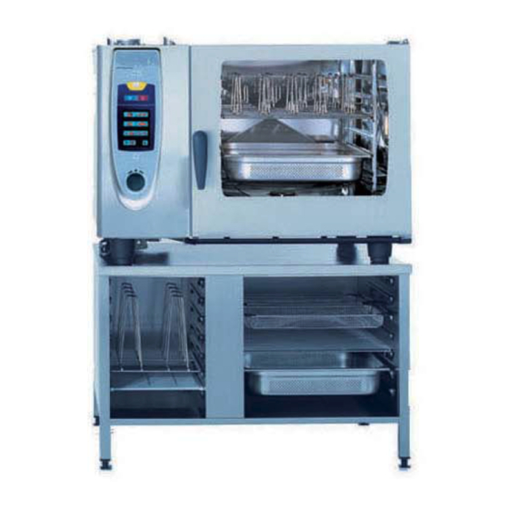
Page 29: Combiduo, Thermo Cabinet
CombiDuo, Thermo cabinet The following units of SCC line can be combined as a CombiDuo: Electric on Electric (E/E) Gas on Gas (G/G) Size 61 on Size 61 Size 61 on Size 61 Size 61 on Size 101 Size 61 on Size 101 Size 61 on Size 62 Size 61 on Size 62 Size 61 on Size 102... -
Page 30: Sicotronic
Sicotronic Sicotronic: energy management systems and energy optimization plants for electro-thermal and general electrical devices in a large-scale catering establishment. Industrial customers pay electricity rate according to a maximum of Power consumption. Should the amp draw exceed a set maximum the power supply company will charge a higher permium per KWh. In order to avoid this current peak a surveyance system like Sicotronic is connected to the Power meter which will disconnect individual consumers for a certain time according to a preset priority list. - Page 31 - 31 - V03 EN, Fundamentals...
-
Page 32: Product Surveillance Guideline
RATIONAL products. Safety-related market incidents - An accident with injury to a person or property damage which occurs after installing a RATIONAL product or - Factors, which could either directly or indirectly endanger the health or life of a person or damage property. -
Page 33: Registration Form Product Surveillance
Other remarks: (measures carried out or arranged; whereabouts of appliance/parts; info to specialist dealer, chimney sweep, end-user etc.; informed authority, expert, police etc.) Report on findings required? yes / no If you exchanged service parts, pls return to RATIONAL Parcel number / Tracking number: Landsberg, QM-R, as soon as possible! -
Page 34: Registration Form „Dead On Arrival
Customers Address: / Service Company / Name of Technician who Kundenadresse: reported the fault: / Adresse des Rational Service Partners / Name des Technikers, der die Meldung gemacht hat: Fault description: / Fehlerbeschreibung: Fault remedy (if repaired) + service parts used/exchanged: / Fehlerbehebung (falls erfolgreich) u. -
Page 35: Warranty Conditions
“X” at „No“, then it is rejected and/or this concerns a wearing part. Column “part back”, is registered with an „X” at „Yes“, then please send the part back to RATIONAL, is it registered with an „X” at „ No“, then that Part can be locally disposed... - Page 36 Parts can be collected and send back also on a 2 – 3 months basis. Credit Note: Parts listed on the warranty report, which do not have to be send back to RATIONAL, Landsberg, will be credited as soon as possible.
- Page 37 Warranty conditions - 37 - V03 EN, Fundamentals...
- Page 38 V03 EN, Fundamentals - 38 -...
- Page 39 - 39 - V03 EN, Fundamentals...
- Page 40 Service Parts: Fax: +49 (0)8191-327408 e-mail: rational.ersatzteile@rational-online.com Chef Line: Phone: +49 (0)8191-327300 Please note that any technical information concerning Rational products must NOT be forwarded to any third party. 80.51.101 - V03 EN - RTS/Md 10/2010...
Need help?
Do you have a question about the SelfCooking Center Combi Master and is the answer not in the manual?
Questions and answers