Advertisement
Quick Links
Freescale Semiconductor
User's Guide
S12ZVM12EVB Evaluation Board
User Guide
1 Introduction
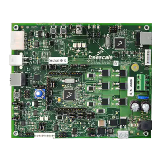
The S12ZVMx12EVB board is designed to drive 3-phase
BLDC or PMSM motors, enabling implementation of motor
control techniques:
• Sensor-less:
• Back-EMF signal sensing using the MCU
integrated ADC modules
• Back-EMF zero-cross signal monitoring using
MCU integrated comparators
• Sensor-based:
• Hall sensor signal monitoring
• Resolver sin/cos signal monitoring
The board features the S12ZVM, a 16-bit automotive
microcontroller from the MagniV family. This System on
Chip integrates an S12Z microcontroller with a Local
Interconnect Network (LIN) physical interface, a 5-V
regulator and a Gate Driver Unit (GDU). The motor power
stage comprises 6 N-channel power MOSFETs that are
controlled by the MCU integrated GDU.
A USB to SCI interface is available and can be used for
FreeMaster PC-based application control. An integrated
OSBDM debugger interface is also provided for easy
programming/debugging of the S12ZVM microcontroller
device.
The board is available in the following versions:
• S12ZVML12EVBLIN - Features the
MC9S12ZVML12, with integrated LINPHY
© 2016 Freescale Semiconductor, Inc.
Document Number: MC9S12ZVM128MCBUG
Contents
1
Introduction................................................................1
2
Interface Description.................... .............................4
3
Design Considerations.................... ........................ 11
4
Motor Control Kit Board Set-Up........... ................. 29
5
Electrical Characteristics................ .........................30
6
References.............................. ................................. 30
7
S12ZVMxEVB Board Schematics..... .................... 31
Rev. 2, 03/2016
Advertisement

Subscribe to Our Youtube Channel
Related Manuals for NXP Semiconductors S12ZVM12EVB


Summary of Contents for NXP Semiconductors S12ZVM12EVB
-
Page 1: Table Of Contents
Freescale Semiconductor Document Number: MC9S12ZVM128MCBUG User's Guide Rev. 2, 03/2016 S12ZVM12EVB Evaluation Board User Guide Contents 1 Introduction Introduction..............1 The S12ZVMx12EVB board is designed to drive 3-phase Interface Description..........4 BLDC or PMSM motors, enabling implementation of motor Design Considerations..........11 control techniques: •... - Page 2 • 1 general-purpose, user configurable switch • Optional 4 MHz external oscillator • 1 general-purpose Potentiometer 1.2 Board Architecture The S12VMx12EVB Controller Board basic building blocks are depicted in the following figure. S12ZVM12EVB Evaluation Board User Guide, Rev. 2, 03/2016 Freescale Semiconductor, Inc.
- Page 3 (PMF) inside the MCU. The PMF module can drive the different channels independently or in complementary pairs, with automatic dead time insertion.Several FAULT monitoring comparators are connected to the PMF’s external FAULT pin. The settings for FAULT triggering can be configured using on-board potentiometers. S12ZVM12EVB Evaluation Board User Guide, Rev. 2, 03/2016 Freescale Semiconductor, Inc.
-
Page 4: Interface Description
2.2 Alternative Power Supply, J64 and J65 The S12VMx12EVB board can also be supplied either by populating a blade terminal on both J64 (positive) and J65 (ground reference) for applications requiring higher current capabilities. S12ZVM12EVB Evaluation Board User Guide, Rev. 2, 03/2016 Freescale Semiconductor, Inc. - Page 5 The output of the filter stage drives the resolver reference winding (RES_GENP/RES_GENM). The resolver sine and cosine signals are input into a conditioning circuitry that adjusts voltage levels down to the range acceptable to the on-chip ADC module. S12ZVM12EVB Evaluation Board User Guide, Rev. 2, 03/2016 Freescale Semiconductor, Inc.
- Page 6 AN1_1 (through J50) or Resolver Sensor COS Analog Input AN1_3 (through J52) Input AGND — Analog ground Power Reference reference +5 VA — 5 V supply voltage Power Supply S12ZVM12EVB Evaluation Board User Guide, Rev. 2, 03/2016 Freescale Semiconductor, Inc.
- Page 7 MCU. Table 7. LINPHY interface header Interface pin Signal name MCU signal Description Direction LPRXD LPRXD LIN Physical Layer Digital Output LPTXD LPTXD LIN Physical Layer TXD Digital Input S12ZVM12EVB Evaluation Board User Guide, Rev. 2, 03/2016 Freescale Semiconductor, Inc.
- Page 8 Power Reference — — (Not connected) — U_RESET RESET Reset Digital Bidirectional — — (Not connected) — +5 VU VDD1 5 V supply from Power Supply OSBDM USB interface S12ZVM12EVB Evaluation Board User Guide, Rev. 2, 03/2016 Freescale Semiconductor, Inc.
- Page 9 The MCU signals from GPIO port P can be monitored using this header. Table 13. MCU Port P header Interface pin MCU signal Pin functionality PP0/EVDD1/KWP0/(PWM0)/ECLK/ FAULT5/XIRQ PP1/KWP1/(PWM1)/IRQ PP2/KWP2/(PWM2) Ground reference S12ZVM12EVB Evaluation Board User Guide, Rev. 2, 03/2016 Freescale Semiconductor, Inc.
- Page 10 The MCU signals from GPIO port S can be monitored using this header. Table 16. MCU Port S header Interface pin MCU signal Pin functionality PS0/KWS0/RXD1/RXCAN/(LPRXD)/ PTUT0 PS1/KWS1/TXD1/TXCAN/(LPTXD)/ PTUT1 PS2/KWS2/(RXD1)/MISO PS3/KWS3/DBGEEV/(TXD1)/MOSI PS4/KWS4/SCK/PDOCLK PS5/KWS5/SS/PDO Ground reference S12ZVM12EVB Evaluation Board User Guide, Rev. 2, 03/2016 Freescale Semiconductor, Inc.
-
Page 11: Design Considerations
• Low side and high side FET pre-drivers for each phase • Gate drive pre-regulator • LDO (Low Dropout Voltage Regulator) (typically 11 V) • High side gate supply generated using bootstrap circuit with external diode and capacitor S12ZVM12EVB Evaluation Board User Guide, Rev. 2, 03/2016 Freescale Semiconductor, Inc. - Page 12 Diode D21 provides protection to the BOOST pin in case of a reverse battery condition. If the VBAT node shown in the figure below is already protected against a reverse battery condition, the diode D21 is not needed. S12ZVM12EVB Evaluation Board User Guide, Rev. 2, 03/2016 Freescale Semiconductor, Inc.
- Page 13 Q10, turns on and isolates the HD pin from VBAT by opening the external MOSFET. Figure 4. Reverse Battery Protection and Charge Pump circuit S12ZVM12EVB Evaluation Board User Guide, Rev. 2, 03/2016 Freescale Semiconductor, Inc.
- Page 14 • S12ZVML12EVBLIN, populated with the MC9S12ZVML12 device that integrates a LIN physical layer • S12ZVMC12EVBCAN, populated with the MC9S12ZVMC12 device that integrates a controller for a second 5 V voltage regulator to supply an external CAN transceiver. S12ZVM12EVB Evaluation Board User Guide, Rev. 2, 03/2016 Freescale Semiconductor, Inc.
- Page 15 In this case, the battery voltage is taken from the HD node, the supply to the FET bridge high side drains. S12ZVM12EVB Evaluation Board User Guide, Rev. 2, 03/2016 Freescale Semiconductor, Inc.
- Page 16 CAN transceiver. The transceiver 5 V supply can be powered from the USB connector, J25, as long as a jumper is populated on header J3. In this case, the jumper on header J2 must be removed. S12ZVM12EVB Evaluation Board User Guide, Rev. 2, 03/2016 Freescale Semiconductor, Inc.
- Page 17 MCU. This voltage is derived from the LDO regulator through an external diode and fed into the bootstrap voltage VBSx pin. Each high-side driver uses the pin HSx as its reference, and supplies the bootstrap voltage into pin HGx to drive the high-side MOSFET gate. S12ZVM12EVB Evaluation Board User Guide, Rev. 2, 03/2016 Freescale Semiconductor, Inc.
- Page 18 The internal current sense amplifier 0 is mapped to the ADC pins at PAD0, PAD1, and PAD2, with the following configuration: PAD0 = AMP0, the operational amplifier output. PAD1 = AMPM0, the operational amplifier inverting input (minus). PAD2 = AMPP0, the operational amplifier non-inverting input (plus). S12ZVM12EVB Evaluation Board User Guide, Rev. 2, 03/2016 Freescale Semiconductor, Inc.
- Page 19 The output voltage is shifted up by 2V5_REF, a 2.5 V supply which is mid range from the full scale voltage of the ADC, 5 V, to accommodate positive and negative current swings. The voltage shift can be eliminated by removing R196 and replacing it with R197 instead. S12ZVM12EVB Evaluation Board User Guide, Rev. 2, 03/2016 Freescale Semiconductor, Inc.
- Page 20 This amplifier has fixed connections to the Phase B current sense resistor. The external gain setting resistors have the same values as described before. It is also connected to a 2.5 V reference to allow for positive and negative current swings. S12ZVM12EVB Evaluation Board User Guide, Rev. 2, 03/2016 Freescale Semiconductor, Inc.
- Page 21 ADC channels. The gain setting resistors have the same values as in the previous two cases, with the connection to a 2.5V reference voltage for positive and negative current swings. S12ZVM12EVB Evaluation Board User Guide, Rev. 2, 03/2016 Freescale Semiconductor, Inc.
- Page 22 Figure 14. Phase A current sense using external Op-Amp 3.8 ADC Channel Mapping The following figures show the jumper configurations for the different ADC external channel mapping options: Figure 15. Resolver interface plus 3-phase sensing S12ZVM12EVB Evaluation Board User Guide, Rev. 2, 03/2016 Freescale Semiconductor, Inc.
- Page 23 The on-board interface provides the 5 V power supply voltage to supply the sensors. The Hall interface inputs are designed to support an open collector as well as push-pull Hall sensors outputs (see Figure below). A single pole RC low pass filter is present to reduce a signal noise. S12ZVM12EVB Evaluation Board User Guide, Rev. 2, 03/2016 Freescale Semiconductor, Inc.
- Page 24 2-3 of header J15. For Phase B, a jumper must be placed on pins 1-2 of header J16. For phase C, there is a 0-ohm resistor that links it directly to the microcontroller pin PT3. Figure 19. Hall Sensor routing options S12ZVM12EVB Evaluation Board User Guide, Rev. 2, 03/2016 Freescale Semiconductor, Inc.
- Page 25 The resolver interface is included to observe motor rotor position. The board is populated with the hardware interface to measure motor position and speed. The resolver connector can be connected to J62. For detailed description, see application note AN1942 or patent WO/2007/137625. S12ZVM12EVB Evaluation Board User Guide, Rev. 2, 03/2016 Freescale Semiconductor, Inc.
- Page 26 Phase A, a jumper must be placed on pins 2-3 of header J15. For Phase B, a jumper must be placed on pins 1-2 of header J16. For phase C, there is a 0- ohm resistor that links it directly to the microcontroller pin PT3. Figure 22. Resolver input interface S12ZVM12EVB Evaluation Board User Guide, Rev. 2, 03/2016 Freescale Semiconductor, Inc.
- Page 27 J37 and J53, respectively. Because the PS4 and PS5 pins are also available as part of the extended debug option, care must be taken when populating the jumpers on headers J37 and J53. Figure 24. User LED options S12ZVM12EVB Evaluation Board User Guide, Rev. 2, 03/2016 Freescale Semiconductor, Inc.
- Page 28 “Phase A” input from a Resolver, a Hall Sensor, or a Quadrature Encoder, care must be taken when populating the jumper on J9 that links the SPDT switch to port PT1. Figure 26. User switch option S12ZVM12EVB Evaluation Board User Guide, Rev. 2, 03/2016 Freescale Semiconductor, Inc.
-
Page 29: Motor Control Kit Board Set-Up
The S12ZVML12EVBLIN is also available as part of a motor control kit that includes a 3-phase BLDC motor, along with the application code to run the BLDC motor with sensorless control using Back-EMF zero-crossing detection. The Motor Control Kit based on the S12ZVML128 MCU can be ordered at http://www.freescale.com/AutoMCDevKits. S12ZVM12EVB Evaluation Board User Guide, Rev. 2, 03/2016 Freescale Semiconductor, Inc. -
Page 30: Electrical Characteristics
1. 12 V Power Supply, MCU without software 6 References All the references can be found in freescale.com. 1. MC9S12ZVM Family Reference Manual, MC9S12ZVMRM 2. S12ZVML12EVBQSG, Quick Start Guide for S12ZVML12EVB evaluation board S12ZVM12EVB Evaluation Board User Guide, Rev. 2, 03/2016 Freescale Semiconductor, Inc. -
Page 31: S12Zvmxevb Board Schematics
4. AN4704, Application Note, 3-phase Sensorless BLDC Motor Control Kit with the S12 MagniV MC9S12ZVM 5. AN1942, Application Note, 56F80x Resolver Driver and Hardware Interface 7 S12ZVMxEVB Board Schematics For a complete list of schematics, see s12zvm-evaluation-board:S12ZVMEVB S12ZVM12EVB Evaluation Board User Guide, Rev. 2, 03/2016 Freescale Semiconductor, Inc. - Page 32 How to Reach Us: Information in this document is provided solely to enable system and software implementers to use Freescale products. There are no express Home Page: or implied copyright licenses granted hereunder to design or fabricate freescale.com any integrated circuits based on the information in this document. Web Support: Freescale reserves the right to make changes without further notice to any products herein.
Need help?
Do you have a question about the S12ZVM12EVB and is the answer not in the manual?
Questions and answers