Lorex L19LD1600 Series Instruction Manual
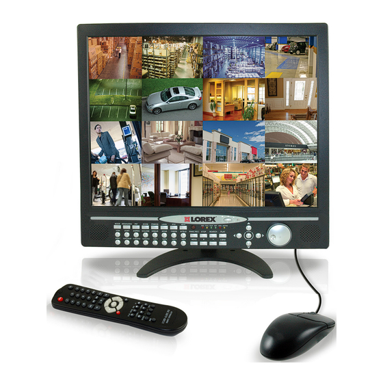
19" lcd color observation system with built-in 16 channel triplex digital video
Hide thumbs
Also See for L19LD1600 Series:
- Quick start manual (13 pages) ,
- Instruction manual (40 pages) ,
- Specifications (3 pages)

Subscribe to Our Youtube Channel
Related Manuals for Lorex L19LD1600 Series


Summary of Contents for Lorex L19LD1600 Series
- Page 1 19" LCD COLOR OBSERVATION SYSTEM With Built-In 16 Channel Triplex Digital Video Instruction Manual English Version 1.0 MODEL: L19LD1600 Series www.lorexcctv.com © Copyright 2008 LOREX Technology Inc.
- Page 2 LCD Monitor with built-in Digital video recorder, cameras, brackets, cables and power supplies. To learn more about this L19LD1600 Series Observation System and to learn about our complete range of accessory products, please visit our website at: CAUTION: TO REDUCE THE RISK OF ELECTRIC SHOCK NO USER SERVICEABLE PARTS INSIDE.
-
Page 3: Important Safeguards
Important Safeguards In addition to the careful attention devoted to quality standards in the manufacture process of your video product, safety is a major factor in the design of every instrument. However, safety is your responsibility too. This sheet lists important information that will help to assure your enjoyment and proper use of the video product and accessory equipment. - Page 4 Important Safeguards Service 13. Servicing - Do not attempt to service this video equipment yourself as opening or removing covers may expose you to dangerous voltage or other hazards. Refer all servicing to qualified service personnel. 14. Conditions Requiring Service - Unplug this video product from the wall outlet and refer servicing to qualified service personnel under the following conditions.
-
Page 5: General Precautions
4. Keep enough space around the unit for ventilation. Slots and openings in the storage cabinet should not be blocked 5. During lightning storms, or when the unit is not used for a long time, disconnect the power supply, antenna, and cables to protect the unit from electrical surge LOREX TECHNOLOGY INC. http://www.lorexcctv.com General Precautions... - Page 6 L19LD1600 Series Feature List L19LD1600 Series Monitor • Multiple easy to use control options: front panel buttons, Remote Control (included) and mouse (included). • On Screen Display: Date, Time, Sequence, Alarm status, Motion, Video loss, Camera title. • Multi-Lingual on screen display (English, French, Spanish, Chinese and Russian) •...
-
Page 7: Table Of Contents
Table of Contents Getting Started ... 9 L19LD1600 Series - Front ... 10~12 L19LD1600 Series - Side ... 13 L19LD1600 Series - Back ... 14 Remote Control ... 15 Camera Installation ... 16 Installation Warnings: ... 16 Camera Stand Installation: ... 16 Connecting Cameras ... - Page 8 Connecting to a PC using the Serial Port - Appendix #6 ... 51 Hard Drive Replacement - Appendix #7 ... 52~53 Play Only Mode - Appendix #8 ... 54 Optional Accessories ... 55 LOREX PRODUCT LIMITED WARRANTY ... 56 Warranty Exclusions ... 56 Obtaining Service ... 57...
-
Page 9: Getting Started
Getting Started Getting Started The L19LD1600 Series comes with the following components: LCD & DVR COMBO UNIT 1 x POWER 1 x MOUSE WITH INSTALLED 160 GB HDD ADAPTOR 1 x 10’ ETHERNET 1 x REMOTE CONTROL 1 x HARDWARE MANUAL... -
Page 10: L19Ld1600 Series - Front
L19LD1600 Series - Front L19LD1600 Series - Front 1. Mode 4. Zoom 7. PTZ 10. LED Indicators 13. Speaker 16.JOG Shuttle 1. DISPLAY MODE - Changes the onscreen camera display between Single, Quad (4 Channel), 6 Channel, 8 Channel, 9 Channel, 13 Channel and 16 Channel Split Screen views. - Page 11 L19LD1600 Series - Front 1. Mode 4. Zoom 7. PTZ 10. LED Indicators 13. Speaker 16.JOG Shuttle 9. PANIC RECORD LED - Indicates that the system is in Panic (Manual Recording) Mode. Press the REC Button to exit. 10. LED STATUS INDICATORS: REC - Indicates that the system is recording.
-
Page 12: L19Ld1600 Series - Front
L19LD1600 Series - Front L19LD1600 Series - Front 1. Mode 4. Zoom 7. PTZ 10. LED Indicators 13. Speaker 16.JOG Shuttle 14. CHANNEL BUTTONS / CONTROLS - Switches the full screen view between channels 1~16. The numbers are also used to enter the System Password. When the system is in PTZ Mode, the buttons control the PTZ Camera. -
Page 13: L19Ld1600 Series - Side
• Press the J SHUTTLE button to exit Jog Shuttle mode. NOTE: This System is PAL Supported. It will automatically detected when PAL type cameras have been connected, and switch to PAL Mode. L19LD1600 Series - Side 1. Removable Drive Bay 4. Volume +/- 1. -
Page 14: L19Ld1600 Series - Back
L19LD1600 Series - Back L19LD1600 Series - Back 1. VGA Out Port 4. RS-232C Port 7. RCA Audio Out 10. Power Adaptor Port 1. VGA OUT - The VGA Port is not functional on this model. 2. ETHERNET - Connects the System to a network router or other Ethernet Device 3. -
Page 15: Remote Control
Remote Control Listed below is a quick reference for the Remote Control. 1. MENU: Press the Menu Button to display the System Configuration. 2. NUMBER KEYPAD: Use to switch between Cameras in live view mode. SEQUENCE MODE: Changes the Monitor Display to Sequence through channels. -
Page 16: Camera Installation
Camera Installation Camera Installation Before you install the camera, carefully plan where and how you will position the camera, and where you will route the cable that connects the camera to the System. Installation Warnings: • Select a location for the camera that provides a clear view of the area you want to monitor, which is free from dust, and is not in line-of-sight to a strong light source or direct sunlight. -
Page 17: Connecting Cameras
Connecting Cameras 1. Connect the Female BNC end of the extension cable to the camera. Connect the male Power end of the extension cable to the camera. * Camera may not be exactly as shown. IMPORTANT NOTE: The ends of the extension cable are NOT the same - one end has a Male power port, and the other has a Female power port. - Page 18 Camera Installation 2. Connect the Female end of the extension cable to an open BNC camera input on the back of the System. Connect the female Power end of the extension cable to the power adaptor. NOTE: To access the Connection Ports for the System, the monitor can be tilted forward (for easier access).
-
Page 19: Connecting The Mouse
Connecting the Mouse Connect the supplied mouse to the PS/2 Port on the back of the unit. • LEFT MOUSE BUTTON - Double click in Viewing Mode to display a camera in Full Screen. Used to adjust values in MENU Mode. •... -
Page 20: Playback Controls
Display Modes Playback Controls Click PLAY icon to switch to the playback interface. Click the SEARCH icon to switch back to the playback interface once playback has started. During Playback, the mouse buttons function as the following controls: Click the PTZ Button to enter PTZ Mode. Display Modes Initial Loading Sequence •... -
Page 21: General Display Overview
General Display Overview 1.TIME - Displays the Current system time, or the recorded time in playback 2.DATE - Displays the Current system date, or the recorded date in playback 3.CAMERA TITLE - Displays the Camera title for the channel. The Camera title can be modified in the SYSTEM MENU ==>... -
Page 22: Screen Display
Display Modes 7. NETWORK CONNECTION - The Network Indicators appear when a remote connection is made to the unit: • Indicates that there is no client connection. • Indicates that a client is connected to the system. 8.HDD RECORD / SEARCH PERCENTAGE - In LIVE Viewing mode, the percentage indicates the amount of HDD space used for recording. -
Page 23: Freeze In Split Mode
Display Modes Freeze in Split Mode In a split screen mode, press the FREEZE button then select a number button to choose the corresponding channel to freeze. Press the number again to cancel. Freeze in Full Mode In full screen mode, press the FREEZE button to freeze the channel, and press FREEZE again to cancel. -
Page 24: Zoom View
Display Modes Zoom View Select a channel to zoom, and press the ZOOM button to enlarge to 200%. Use the direction buttons to move the enlarged part. Use the direction buttons to choose an area and press ENTER to zoom. Press ZOOM again to cancel Key Lock After pressing the LOCK Button, the word LOCK will be displayed on screen, and all buttons are... -
Page 25: Recording Mode
Recording Mode RECORDING MODE: • Indicates that the camera is recording in ALARM Mode. • Indicates that the camera is recording in MOTION DETECTION Mode. • Indicates that the camera is recording in CONTINUOUS Mode. NOTE: If the power is lost, the DVR will automatically resume the recording schedule after the power is back. -
Page 26: Playback
Playback Playback Starting Playback Mode Press the PLAY button on the front panel of the System, or click the onscreen PLAY icon to start playback, starting from the most recent recording. Stopping Playback Mode Press the STOP button on the front panel of the System, or click the onscreen STOP icon to stop the playback. -
Page 27: Search Mode
Search Mode Press the SEARCH button on the front panel of the System, or click the onscreen SEARCH icon to search through previously recorded data. There are 3 modes for search: PERCENT BAR - Search by location a recording point on the bar. -
Page 28: Event List Search
Playback Event List Search • TIME/DATE - Displays the event time and date. • CHANNEL - Displays the channel in which the event occurred. • EVENT - Displays the event type: MOT - Motion detection LOS - Image lost ALM- Alarm trigger The system keeps up to 1000 events in its EVENT LIST. -
Page 29: Playback Controls - Remote Controller
Using the inner circle of the Jog-shuttle to playback video in single frames. Turn clockwise for forward playback and turn counter-clockwise for reverse playback. Playback Controls - Remote Controller • UP Arrow: X times high-speed playback. • DOWN Arrow: X times low speed playback. •... -
Page 30: System Setup And Navigation
System Setup and Navigation Press the MENU button on the Front panel or Remote, or click the onscreen MENU icon to log into system: • Click the 1~0 icons (or use the front panel buttons) to enter the password. • Click ENTER to confirm and enter the system. -
Page 31: Display Setup
Display Setup SCREEN DISPLAY: Controls the settings for the screen in Live and Playback Information display modes. Screen Display Use the UP and DOWN Arrows to select an option, and press the ENTER button to switch between ON and OFF. LIVE: Configure the display settings for the following information (to be displayed onscreen in Live mode):... -
Page 32: Configuration
Configuration Configuration 1. HDD MANAGEMENT - Includes HDD SETUP (HDD Clear), INFORMATION. 2. CAMERA SETUP - Includes CAMERA TITLE and CAMERA COLOR SETUP. 3. MOTION SETUP - Includes SENSITIVITY, DURATION, DETECT CELL NUMBER. 4. ALARM SETUP - Set up the Alarm mode (N.C. -
Page 33: Time / Date Setup
SAVE DVR INFO: Once the ENTER button has been pressed on SAVE DVR INFO, the DVR information will be saved to HDD. • If the DVR information is saved properly, the message NOW CHANGE HDD DISK will be shown on the system. •... - Page 34 Configuration NOTE: When a camera is in Covert Mode, no picture is displayed when in live viewing, however the camera images are still being recorded if Record is set to ON. MOTION SETUP: Program the motion parameters and the detection area CAMERA TITLE: Input the camera Title (max.
-
Page 35: Motion Setup
• STATUS: Indicates the camera status. ACTIVE means the video input status is normal, and LOSS means the video is lost. • COVERT: Set up the channel to be displayed or hidden when on the LIVE screen. • REC: Set up the channel to be record. MOTION SETUP •... - Page 36 Configuration When the window is at the ALL OFF mode, you can activate the motion detection in the block. 5.BLOCK OFF: Block an area to deactivate the motion detection in the desired area. The setup steps are the same as BLOCK ON. If the window is at the ALL ON mode, you can deactivate the motion detection in the block you make.
- Page 37 1.CHANNEL - Use [+] and [-] to select a channel. 2. POPUP ON/OFF - Set up the POPUP function ON/OFF: Use [+] and [-] to select ON or OFF. When there is an event, the screen display will switch to a full screen of the corresponding channel.
-
Page 38: Record Setup
Record Setup The three user levels have different authorities to operate the DVR. System Information Indicate the system information and its status. S/W version: Indicate the firmware version H/W version: Indicate the PCB version Product ID: Indicate the product ID number MASTER 1: Indicate the information of the first HDD MASTER 2: Indicate the information for the... - Page 39 1. OVERWRITE - Sets the Hard Drive to overwrite older data when full. • ON: When the hard drive is full, the system will overwrite the earliest recorded video. If the DVR has two hard drives, the overwriting starts from the Master drive.
-
Page 40: Schedule Record
Record Setup Schedule record Program a recording schedule throughout the week. MODE: Press MODE to select an editing mode. Use the direction keys 3456 to move the cursor, and then press [+] and [-] to select a recording mode. The editing modes are as below: TIME CELL: Program the schedule at a two-hour interval. -
Page 41: Backup
Press MODE and set the editing mode as EDIT HOLIDAY. Use direction key 5634to select and press ENTER to mark the day as a holiday. To clear the settings, press MODE to set the editing mode to CLEAR ALL DATA or CLEAR MON DATA (clear data month by month). -
Page 42: External Device
EXTERNAL DEVICE EXTERNAL DEVICE 1. TCP/IP SETUP - Configure the system Networking information. 2. PAN/TILT SETUP - Set up the parameters of the PTZ control. 3. SPOT SETUP - SPOT output setup. 4. RS232C SETUP - Set up the parameters of the RS232 port. -
Page 43: Tcp/Ip Setup - Speed
minute). Use the Mouse Wheel to change the value. 4. REGISTER - Connect to the DDNS server and register the system information to the server. Click REGISTER to start the registration. 5. DNS STATUS - Indicates the current status of DDNS connection •... -
Page 44: Pan/Tilt Setup - Speed Setup
EXTERNAL DEVICE PAN/TILT SETUP - SPEED SETUP 1. PAN SPEED - Set the PANing speed (0 low ~ 7 high). 2. TILT SPEED - Set the TILTing speed (0 low ~ 7 high). 3. ZOOM SPEED - Set the speed of ZOOM IN/OUT (0 low ~ 7 high). -
Page 45: Observation System Specifications - Appendix #1
Observation System Specifications - Appendix #1 Observation System Specifications - Appendix #1... -
Page 46: Observation System Specifications
Observation System Specifications - Appendix #1 Observation System Specifications - Appendix #1... -
Page 47: Full Connectivity Diagram - Appendix #2
Full Connectivity Diagram - Appendix #2 Full Connectivity Diagram - Appendix #2 The following diagram outlines a general set of connections available with the Observation System. PTZ CAMERA PS/2 ROUTER (Not Included) (Not Included) MOUSE (Not Included) OBSERVATION SYSTEM SLAVE / SPOT OUT BNC CAMERAS SENSOR MONITOR... -
Page 48: Connecting A Slave (Spot-Out) Monitor - Appendix #3
Connecting a Slave (Spot-Out) Monitor - Appendix #3 Connecting a Slave (Spot-Out) Monitor - Appendix #3 Connections to a Slave Monitor / Spot-Out Monitor (not included with the System) can be made through the MONITOR OUT and/or the SPOT OUT ports on the back of the Observation System. A slave monitor can be a TV or Observation System Monitor. -
Page 49: Connecting Motion / Alarm Device - Appendix #4
Connecting Motion / Alarm Device - Appendix #4 Motion detection and Alarm controls are enabled through the Menu system on the Observation System. Additional motion sensor devices can be connected to the system (Motion Sensors, Door/Window Sensors). A motion detection or sensor unit can be used to send a signal to the Observation System to begin camera viewing on the matching Video Channel (when enabled in the Menu, see page 39): •... -
Page 50: Connecting Ptz Cameras - Appendix #5
Connecting PTZ Cameras - Appendix #5 Connecting PTZ Cameras - Appendix #5 PTZ Cameras (not included with this system) can be connected to the PTZ Control Block on the back panel of the System. The PTZ Controls are enabled through the Menu system on the Observation System. -
Page 51: Connecting To A Pc Using The Serial Port - Appendix #6
Connecting to a PC using the Serial Port - Appendix #6 The Observation System can be connected directly to a PC COM Port by using the Serial Port located on the back of the system. • To connect DVR to a PC, users must use a twisted RS232 cable (See below). •... -
Page 52: Hard Drive Replacement - Appendix #7
Hard Drive Replacement - Appendix #7 Hard Drive Replacement - Appendix #7 The System comes with a pre-installed Hard Drive (located in the removable drive bay). This system will work with two (2) installed hard drives (at a max 750GB each). The steps below outline installing a drive in the removable bay - if installing an internal drive, it is recommended to speak with a PC Hardware Technician for assistance. -
Page 53: Hard Drive Replacement - Appendix #7
STEP 4: Reinsert the Cartridge Casing into the DVR • Close the cover on the Drive Case. Fully insert the Cartridge Case into the DVR. STEP 5: Lock the Cabinet Lock the cabinet by turning the key clockwise. Unlocked NOTE: If you do not lock the cabinet, the system will NOT DETECT THE HARD DRIVE and will not function properly. -
Page 54: Play Only Mode - Appendix #8
Play Only Mode - Appendix #8 Play Only Mode - Appendix #8 PLAY ONLY MODE can be used in the following situations: • When you need to playback a hard drive from another System • When you need to playback the video which you deleted by running HDD CLEAR Entering “PLAY ONLY MODE”: 1. -
Page 55: Optional Accessories
Optional Accessories The following accessories are available to add to your existing system: SLAVE / SPOT OUT MONITOR Slave / Spot Out Monitors - View selected Cameras on a second Monitor CAMERAS Accessory PTZ Cameras for additional view control. TO ORDER THESE ACCESSORY ITESMS OR FOR A COMPLETE LISTING OF AVAILABLE PRODUCTS, PLEASE VISIT US ON THE WEB AT: BNC TYPE CAMERAS... -
Page 56: Lorex Product Limited Warranty
Product. In no event shall LOREX be liable for any special or consequential damages arising from the use of the Product or arising from the malfunctioning or non-functioning of the Product, or for any delay in the performance of this warranty due to any cause beyond its control. -
Page 57: Obtaining Service
The Purchaser must provide LOREX with a copy of his/ her original, dated bill of sale, receipt or invoice, failing which LOREX will not perform any of its obligations under this warranty. To claim on this warranty, proceed with the following steps: Pack the Product in a well-padded sturdy carton. - Page 58 It’s all on the web Product Information User Manuals Quick Start Guides VISIT www.lorexcctv.com Lorex Technology Inc. Specification Sheets Software Upgrades Firmware Upgrades www.lorexcctv.com...
Need help?
Do you have a question about the L19LD1600 Series and is the answer not in the manual?
Questions and answers