Table of Contents
Advertisement
Quick Links
UM1589
User manual
M24LR-DISCOVERY kit user guide
Introduction
The M24LR-DISCOVERY kit helps you evaluate the M24LRXX-E Dual Interface EEPROM that features
an energy harvesting analog output, as well as a user-configurable digital output.
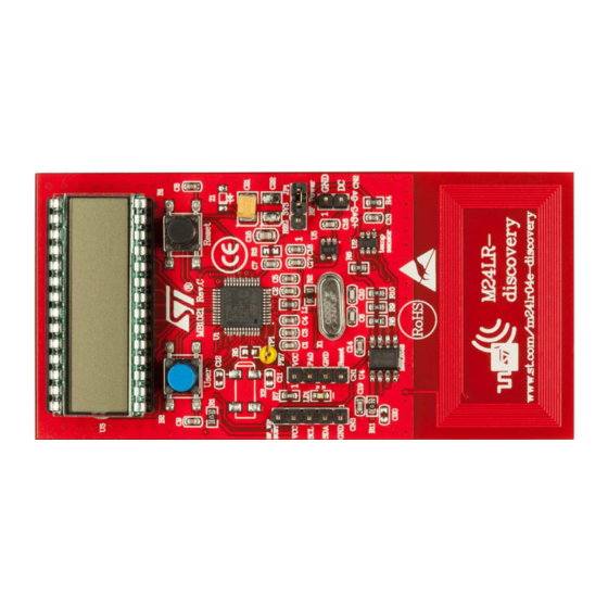
The M24LR-DISCOVERY kit is delivered with a battery-less M24LR board that can be powered by RFID
readers or NFC phones supporting the ISO/IEC15693 protocol. It is based on an M24LR04E-R I²C -
ISO/IEC15693 Dual Interface EEPROM, an 8-bit STM8L152C6T6 ultralow power microcontroller, and
includes an STTS751 temperature sensor, a 24-segment LCD, and 2 push buttons.
The M24LR-DISCOVERY kit also comes with an USB RF transceiver demonstration board that includes
the CR95HF 13.56-MHz multi-protocol contactless transceiver. It is based on a 32-bit, STM32F103CBT6
performance line microcontroller and is connected to a computer host via its USB connector.
Table 1. Applicable tools
Type
Applicable tool
Evaluation tools
M24LR-DISCOVERY
Figure 1. M24LR evaluation board
Figure 2. RF transceiver demonstration board
13 February 2015
DocID023883 Rev 3
1/19
www.st.com
Advertisement
Table of Contents

Subscribe to Our Youtube Channel
Related Manuals for ST M24LR-DISCOVERY


Summary of Contents for ST M24LR-DISCOVERY
-
Page 1: Table 1. Applicable Tools
The M24LR-DISCOVERY kit is delivered with a battery-less M24LR board that can be powered by RFID readers or NFC phones supporting the ISO/IEC15693 protocol. It is based on an M24LR04E-R I²C - ISO/IEC15693 Dual Interface EEPROM, an 8-bit STM8L152C6T6 ultralow power microcontroller, and includes an STTS751 temperature sensor, a 24-segment LCD, and 2 push buttons. -
Page 2: Table Of Contents
Contents UM1589 Contents Quick start ..........5 Getting started with the M24LR04E Dual Interface EEPROM . - Page 3 UM1589 List of tables List of tables Table 1. Applicable tools............1 Table 2.
- Page 4 List of figures UM1589 List of figures Figure 1. M24LR evaluation board........... . 1 Figure 2.
-
Page 5: Quick Start
UM1589 Quick start Quick start The M24LR-DISCOVERY kit is a low-cost and ready-to-use development kit used to evaluate the functions and performance of the M24LR Dual Interface EEPROM family and its energy harvesting capability. For more information on the M24LR-DISCOVERY kit and associated demonstration software, please visit www.st.com/m24lr04e-discovery. -
Page 6: Using The M24Lr Board With Android Nfc Phones
System requirements ® • Windows PC (XP or Vista) • Two USB cables Development toolchain • Cosmic CXSTM8 compiler • STMicroelectronics ST Visual Develop (STVD) integrated development environment • STMicroelectronics STLINK/V2 in-circuit debugger and programmer 6/19 DocID023883 Rev 3... -
Page 7: Features
UM1589 Features Features M24LR board and the RF transceiver board The M24LR-DISCOVERY kit includes which offer the following features. M24LR board • M24LR04E-R, a 4-Kbit EEPROM with an I²C-ISO/IEC 15693 dual interface and an energy harvesting analog output (Vout pin) and a user-configurable digital output (RF Write-in-progress or Busy pin) in an SO8N package •... -
Page 8: Hardware And Layout Description
Hardware and layout description UM1589 Hardware and layout description M24LR board description Figure 3. M24LR board layout 24-segment LCD (U3) Reset button (B1) User button (B2) M24LR board power selection STM8L152C6T6 connector (JP1) microcontroller (U1) SWIM connector (CN1) External power supply connector (CN2) M24LR04E-R and I²C... -
Page 9: M24Lr Board Power Selection
UM1589 Hardware and layout description M24LR board power selection When jumper JP1 is set in the “RF power” position (Figure 4), the M24LR board is powered by the M24LR04E-R energy harvesting analog output (Vout pin). In this configuration, the M24LR board is powered by the magnetic field flowing into its 9-turn, etched loop antenna, delivered from a 13.56-MHz RF source, such as an RFID reader or an NFC phone. -
Page 10: Figure 6. External Antenna Connection With Voltage Regulator Bypass
Hardware and layout description UM1589 Figure 6 Figure 7 illustrate the use of an external antenna using the ANT1-M24LR16E demonstration board. • Figure 6 shows a possible direct connection of the Vout voltage coming from the ANT1- M24LR16E antenna demo board on jumper JP1 to bypass the voltage regulator (U5). •... -
Page 11: Rf Transceiver Board Description
UM1589 Hardware and layout description RF transceiver board description Figure 8. RF transceiver board layout (top and bottom) connector (J1) LDO regulator User LED 1 STM32F103CBT6 20-pin JTAG connector (J3) 27.12-MHz crystal oscillator CR95HF RF IC Reset button 2-turn,13.56-MHz loop antenna RF transceiver demonstration board powering and startup The RF transceiver demonstration board is powered by the USB bus. -
Page 12: Program/Debug The M24Lr Board
20-pin JTAG/SWD flat ribbon of the STLINK/V2 in- circuit debugger and programmer to the RF transceiver demonstration board JTAG connector (J2). For more information, documentation about the STLINK/V2 in-circuit debugger and programmer, please visit www.st.com 12/19 DocID023883 Rev 3... -
Page 13: Federal Communications Commission (Fcc) And Industry Canada (Ic) Compliance Statements
UM1589Federal Communications Commission (FCC) and Industry Canada (IC) Compliance State- Federal Communications Commission (FCC) and Industry Canada (IC) Compliance Statements FCC Compliance Statement 4.1.1 Part 15.19 This device complies with Part 15 of the FCC Rules. Operation is subject to the following two conditions: (1) this device may not cause harmful interference, and (2) this device must accept any interference received, including interference that may cause undesired operation. - Page 14 Federal Communications Commission (FCC) and Industry Canada (IC) Compliance Statements (1) l’appareil ne doit pas produire de brouillage, et (2) l’utilisateur de l’appareil doit accepter tout brouillage radioélectrique subi, même si le brouillage est susceptible d’en compromettre le fonctionnement. IC ID: 8976A-DEMOCR95HF 14/19 DocID023883 Rev 3...
-
Page 15: Electrical Schematic Diagrams
Electrical schematic diagrams Figure 9. M24LR board schematics... -
Page 16: Figure 10. Rf Transceiver Demonstration Board Schematics (Stm32 Connections)
Figure 10. RF transceiver demonstration board schematics (STM32 connections) -
Page 17: Figure 11. Rf Transceiver Demonstration Board Schematics (Cr95Hf Connections)
Figure 11. RF transceiver demonstration board schematics (CR95HF connections) -
Page 18: Revision History
Revision history UM1589 Revision history Table 4. Document revision history Date Revision Changes 06-Nov-2012 Initial release. Replaced “M24LR/CR95HF demonstration software " by "M24LR/CR95 application software setup file [STSW-M24LR011]" in Section 1.1 Section 3.4. 11-Mar-2013 Replaced “M24LRxx_Application_Software.exe” by “setup.exe” in Section 1.1. - Page 19 ST products and/or to this document at any time without notice. Purchasers should obtain the latest relevant information on ST products before placing orders. ST products are sold pursuant to ST’s terms and conditions of sale in place at the time of order acknowledgement.
Need help?
Do you have a question about the M24LR-DISCOVERY and is the answer not in the manual?
Questions and answers