Kobold NE-104 Operating Instructions Manual
Electrode relays for conductive level switches
Hide thumbs
Also See for NE-104:
- Operating instructions manual (12 pages) ,
- Operating instructions manual (19 pages)

Related Manuals for Kobold NE-104


Summary of Contents for Kobold NE-104
- Page 1 Operating Instructions Electrode Relays for Conductive Level Switches Model: NE (without WHG-certification)
-
Page 2: Table Of Contents
Operating Principle ..................4 Mechanical Connection ................. 5 Electrical Connection ..................5 7.1. Electrode relay NE-104 ................ 5 7.2. Electrode relay NE-304 ................ 6 Commissioning.................... 10 Locating and Remedying Faults ..............11 ... -
Page 3: Note
Please read these operating instructions before unpacking and putting the unit into operation. Follow the instructions precisely as described herein. The instruction manuals on our website www.kobold.com are always for currently manufactured version of our products. Due to technical changes, the instruction manuals available online may not always correspond to the product version you have purchased. -
Page 4: Regulation Use
The medium conductivity must be min. 20S/cm. Electrode relay The model NE-104 or NE-304 electrode relay controls the conductive electrodes and switches throughput, when the conductivity changes. Model 104: For one switching point with one electrode and one earth electrode. -
Page 5: Mechanical Connection
EMC-critical installation environement. The cable needs to be connected to an adequate shield ground. 7.1. Electrode relay NE-104 The NE-104 electrode relay is the standard relay for all conductive limit electrodes. It is supplied as a break relay, i.e., the relay picks up (contact 6-7 closes) when auxiliary power is applied. -
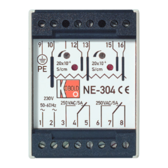
Page 6: Electrode Relay Ne-304
Electrode connection Usage as Min/Max switch (2 electrodes) Connect the earth or reference electrode to terminal 14. Connect the switching electrode to terminal 15. Level Relay Below the switching electrode relay picks up, contact 6-7 closed Reaches or above the switching electrode relay drops out, contact 7-8 closed Use for interval control (3 electrodes) ... - Page 7 Electrode connection Usage as MIN/MAX switch (3 electrodes Connect the earth or reference electrode to terminal 10. Connect MIN.-switching electrode to terminal 12 and the MAX.-switching electrode to terminal 15. Level Relay Min.-Electrode Reaches or above the switching electrode relay drops out, contact 4-5 closed Below the switching electrode relay picks up, contact 3-4 closed Max.-Electrode...
- Page 8 The mains voltage is terminated at terminals 1 and 2, and the protective earth conductor at terminal 9 (PE). Note: Terminal 10 (earth) is internally linked to terminal 9 (PE). Connection Diagrams – examples of use model NE-104 Power supply...
- Page 9 Power supply Fill container Power supply Overflow protection Power supply Power supply NE K06/1022 page 9...
-
Page 10: Commissioning
Minimum level protection Power supply Power supply 8. Commissioning Turn the sensitivity potentiometer fully clockwise to the right, until the stop is reached. When the main voltage has been connected, and the electrodes have been connected according to their required function, the conductive limit switch is ready for operation. -
Page 11: Locating And Remedying Faults
If the LED is energised Relay model NE-104: Disconnect the electrode from terminals 14, 15, and 16, and short-circuit terminals 14 and 15 with a wire jumper. The relay must drop out now. If there is no reaction, the relay is faulty. -
Page 12: Technical Information
10 VA Short-circuit-current: approx. 0.5 mA Sensitivity: adjustable 0 - 50 kOhm Response time: approx. 1 s Output: NE-104: 1 floating changeover contact NE-304: floating changeover contacts Switching capacity: max. 250 V , 5 A, 600 VA Housing: Macrolone Protection:... -
Page 13: Dimensions
13. Dimensions NE K06/1022 page 13... -
Page 14: Disposal
14. Disposal Note! Avoid environmental damage caused by media-contaminated parts Dispose of the device and packaging in an environmentally friendly manner Comply with applicable national and international disposal regulations and environmental regulations. Batteries Batteries containing pollutants are marked with a sign consisting of a crossed-out garbage can and the chemical symbol (Cd, Hg, Li or Pb) of the heavy metal that is decisive for the classification as containing pollutants: 1. -
Page 15: Eu Declaration Of Conformance
15. EU Declaration of Conformance We, KOBOLD Messring GmbH, Hofheim-Ts, Germany, declare under our sole responsibility that the product: Electrode Relays for Conductive Level Switches Model: NE-104, NE-304 to which this declaration relates is in conformity with the standards noted below:...
Need help?
Do you have a question about the NE-104 and is the answer not in the manual?
Questions and answers