Table of Contents
Advertisement
Quick Links
Advertisement
Table of Contents

Subscribe to Our Youtube Channel
Related Manuals for TRENDnet TPE-3012LS


Summary of Contents for TRENDnet TPE-3012LS
- Page 1 Cover Page TRENDnet User’s Guide...
-
Page 2: Table Of Contents
Set your IPv6 settings ..................43 Clock Settings ..................... 19 Set the switch date and time ................45 SNTP Settings ..................... 19 Set the web management idle timeout ............. 46 Surveillance Settings ....................21 Port ..........................47 © Copyright 2020 TRENDnet. All Rights Reserved. - Page 3 View the switch MAC address table ..............75 Configure Management Access ............... 110 Add static MAC address entries ................. 75 Configure Management ACL/ACE (Access Control Lists/Access Control Entries) Add MAC Addresses used in filtering ..............76 ......................... 112 © Copyright 2020 TRENDnet. All Rights Reserved.
- Page 4 Configure Port Mirroring ................. 144 Ping Test ......................145 Ping Watchdog ....................146 Traceroute ....................... 147 Copper Test ...................... 147 Fiber Module ....................148 UDLD ........................ 149 View UDLD Neighbors ..................151 Management ......................152 © Copyright 2020 TRENDnet. All Rights Reserved.
-
Page 5: Product Overview
• Power cord (1.5m/5 ft.) • Rackmount kit If any package contents are missing or damaged, please contact the retail store, online retailer, or reseller/distributor from which the product was purchased. TPE-3012LS TPE-3018LS © Copyright 2020 TRENDnet. All Rights Reserved. -
Page 6: Features
They also support long distance PoE+ networking IPv6 Ready up to 656 ft./200m away at speeds up to 10mbps. TRENDnet’s Gigabit PoE+ Smart Surveillance Switches also feature SFP slots to support long-distance fiber networking ONVIF switches support IPv6 configuration and IPv6 neighbor discovery applications. -
Page 7: Product Hardware Features
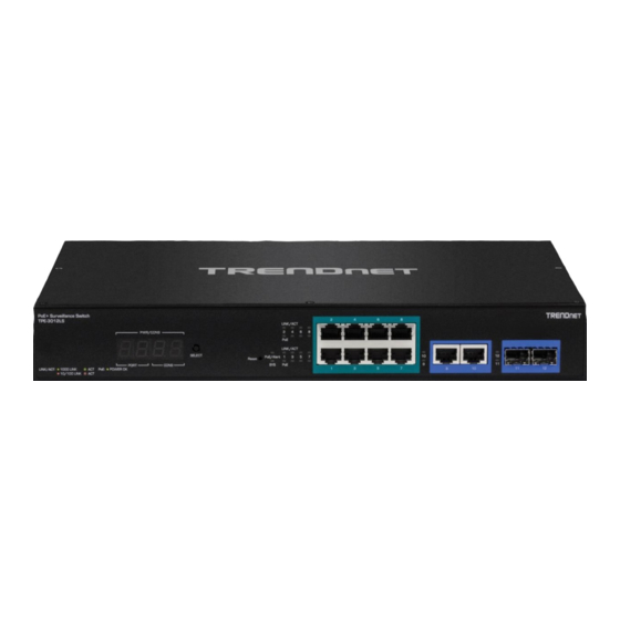
Gigabit Ports (9-10) – Connect non-PoE devices or uplinks. • SFP Slots (11-12) – Supports optional 1000BASE-SX/LX mini-GBIC Green/Amber Green indicates the link is connected at 1000Mbps. modules. Amber indicates the link is connected at © Copyright 2020 TRENDnet. All Rights Reserved. - Page 8 PoE+ Gigabit Ports (1-16) – Connect PoE and non-PoE network devices. • Gigabit Ports (17-18) – Connect non-PoE devices or uplinks. Disabled if SFP slots 17F or 18F are used. • SFP Slots Shared (17F-18F) – Supports optional 1000BASE-SX/LX mini- GBIC modules. © Copyright 2020 TRENDnet. All Rights Reserved.
- Page 9 : When the Link/ACT LED lights on, the respective port is successfully connected to an Ethernet network. Green/Amber Green indicates the link is connected at 1000Mbps. Amber indicates the link is connected at © Copyright 2020 TRENDnet. All Rights Reserved.
-
Page 10: Application Diagram
PoE devices or reboot the switch if the PoE devices are unresponsive. The switches to your network through the non-PoE Gigabit Ethernet uplink port or SFP fiber to a switch that is connected to your network. © Copyright 2020 TRENDnet. All Rights Reserved. -
Page 11: Switch Installation
• When installing the Switch on a level surface, attach the rubber feet to the bottom of each device. The rubber feet cushion the hub and protect the hub Then, use screws provided with the equipment rack to mount each switch in the rack. case from scratching. © Copyright 2020 TRENDnet. All Rights Reserved. -
Page 12: Basic Installation
Enter. The default IP address is 192.168.10.200. 5. Enter the User Name and Password, and then click Login. By default: User Name: admin Password: admin Note: User name and password are case sensitive. © Copyright 2020 TRENDnet. All Rights Reserved. - Page 13 10. On the final setup wizard page, you can check the “Ignore the wizard next time” option to prevent the setup wizard prompt from appearing at the next login to the web management interface, then click Apply. © Copyright 2020 TRENDnet. All Rights Reserved.
-
Page 14: Connect Additional Devices To Your Switch
You can connect additional computers or other network devices PoE (Power over Ethernet) or non-PoE devices to your switch using Ethernet cables to connect them to one of the available PoE+ Gigabit Ports (TPE-3012LS PoE+ ports 1-8 / TPE-3018LS PoE+ ports 1-16) or Gigabit ports (TPE-3012LS Gigabit ports 9-10 / TPE-3018LS Gigabit ports 17-18). Check the status of the LED indicators on the front panel of your switch to ensure the physical cable connection from your computer or device. -
Page 15: Access Your Switch Management Page
You can also click Management, click on Configuration, and click on Save Configuration. In the main window, click Apply with the Running config as the source and Startup config as the destination to save changes to NV-RAM. © Copyright 2020 TRENDnet. All Rights Reserved. -
Page 16: Switching Between Standard And Surveillance Mode Web Interfaces
By default, the Standard mode GUI is You can manually switch between web interface modes using the buttons noted below. configured. Standard Mode GUI Surveillance Mode GUI © Copyright 2020 TRENDnet. All Rights Reserved. -
Page 17: Surveillance Mode Web Interface
• IP Address – Displays the currently assigned IPv4 address. • Mask – Displays the currently assigned IPv4 subnet mask. • Gateway – Displays the currently assigned IPv4 default gateway. • MAC Address – Displays the switch MAC address. © Copyright 2020 TRENDnet. All Rights Reserved. -
Page 18: Overview
1. Log into your switch management page (see “Access your switch management page” on page 11). 2. Click on TPE-3012LS or TPE-3018LS (depending on the switch model) in the top left and click the Overview tab. Port Number PoE On/Off Button: Click... -
Page 19: Port Info
11). 2. Click on TPE-3012LS or TPE-3018LS (depending on the switch model) in the top left and click the Port Info tab. 2. Click on TPE-3012LS or TPE-3018LS (depending on the switch model) in the top left and click the IP Camera Info tab. -
Page 20: Nvr Info
11). on page 11). 2. Click on TPE-3012LS or TPE-3018LS (depending on the switch model) in the top left 2. Click on TPE-3012LS or TPE-3018LS (depending on the switch model) in the top left and click the NVR Info tab. -
Page 21: Poe Scheduling
5. Click Save in the top left menu to save configuration to NV-RAM. Item Description Range Name Select Range name. Days Select a valid time for this schedule. Input the Start Time. Start Time End Time Input the End Time. © Copyright 2020 TRENDnet. All Rights Reserved. - Page 22 Select an entry to to configure PoE port scheduling and click Edit. 4. After completing your configuration changes, click Apply. 5. Click Save in the top left menu to save configuration to NV-RAM. © Copyright 2020 TRENDnet. All Rights Reserved.
-
Page 23: Time
4. After completing your configuration changes, click Apply. Input manual time. This is enabled when time source is Time manual. Daylight Saving Time 5. Click Save in the top left menu to save configuration to NV-RAM. © Copyright 2020 TRENDnet. All Rights Reserved. - Page 24 From mode. 5. Click Save in the top left menu to save configuration to NV-RAM. Non recurring Specify the ending time of recurring daylight saving time. This field available when selecting “Non-Recurring” mode. © Copyright 2020 TRENDnet. All Rights Reserved.
-
Page 25: Ip Settings
No Security: Specify that no packet authentication is performed. Security Level • Authentication: Specify that no packet authentication without encryption is performed. • Authentication and Privacy: Specify that no packet authentication with encryption is performed. © Copyright 2020 TRENDnet. All Rights Reserved. -
Page 26: Log Server
Error: System is in error condition • Warning: System warning has occurred has occurred. • • Notice: System is functioning properly, but a system notice Informational: Device information. • Debug: Provides detailed information about an event. © Copyright 2020 TRENDnet. All Rights Reserved. -
Page 27: Password Settings
• Send Test: Use this to verify your SMTP email configuration settings are configured correctly and email notification is working properly. 4. After completing your configuration changes, click Apply. 5. Click Save in the top left menu to save configuration to NV-RAM. © Copyright 2020 TRENDnet. All Rights Reserved. -
Page 28: Pd Alive Check
PoE port. (Range: 1-5) • Action – An option must be selected for PD alive check to function. None – If the ping response fails according to the time parameters set, no action will be taken. © Copyright 2020 TRENDnet. All Rights Reserved. -
Page 29: Onvif
4. After completing your configuration changes, click Apply. 5. Click Save in the top left menu to save configuration to NV-RAM. © Copyright 2020 TRENDnet. All Rights Reserved. -
Page 30: Applying Ip Address Settings To Onvif Authorized Devices
Note: If you are unable to successfully authorize the IP camera, please double check 3. For the ONVIF devices that have been successfully authorized, check the device in the your ONVIF administrator credentials. You can also try to reboot the IP camera. list and click Edit. © Copyright 2020 TRENDnet. All Rights Reserved. - Page 31 5. Scroll down the window to view or modify the device IP address configuration. 6. After you have applied configuration changes, scroll to the bottom of the window and click Apply. A success message will appear if the configuration changes were successfully applied. © Copyright 2020 TRENDnet. All Rights Reserved.
-
Page 32: Changing The Onvif Device Administrator Password
Apply. A success message will appear if the configuration changes were ONVIF device will be listed. To modify the ONVIF administrator password, check the successfully applied. device in the list with User Level admin and click Edit. © Copyright 2020 TRENDnet. All Rights Reserved. -
Page 33: Creating New Onvif Users In The Onvif Device
Apply. A success message will appear if the configuration changes were ONVIF device will be listed. To create a new ONVIF user for the device, check the device successfully applied. in the list and click Add. © Copyright 2020 TRENDnet. All Rights Reserved. -
Page 34: Upgrade Onvif Device Firmware
Note: If you have multiple devices of the same model that use the same firmware file, you can upgrade multiple devices of the same model by checking multiple devices in the list before clicking Upgrade. © Copyright 2020 TRENDnet. All Rights Reserved. -
Page 35: E-Map Management
Apply to start the upload. 4. The file name of the image will be displayed after it has been successfully uploaded. © Copyright 2020 TRENDnet. All Rights Reserved. - Page 36 Note: Clicking Reset will reset the e-map to default and remove all IP cameras from the floorplan moved back to the top left of the e-map. 4. After completing your configuration changes, click Apply. 5. Click Save in the top left menu to save configuration to NV-RAM. © Copyright 2020 TRENDnet. All Rights Reserved.
-
Page 37: Tools
2. In the top left menu, click on Tools and click on Firmware Information. HTTP Item Description Firmware operations • Action Upgrade: Upgrade firmware from remote host to DUT. • Backup: Backup firmware image from DUT to remote host. © Copyright 2020 TRENDnet. All Rights Reserved. - Page 38 Upgrade: Upgrade firmware from remote host to DUT • Backup: Backup firmware image from DUT to remote host Firmware upgrade / backup method • Method TFTP: Using TFTP to upgrade/backup firmware. • HTTP: Using WEB browser to upgrade/backup firmware. © Copyright 2020 TRENDnet. All Rights Reserved.
-
Page 39: Backup/Restore Switch Configuration
Backup Configuration: Replace backup configuration file Use browser to upgrade configuration, you should select Filename • Startup Configuration: Replace startup configuration file configuration file on your host PC. • Backup Configuration: Replace backup configuration file © Copyright 2020 TRENDnet. All Rights Reserved. -
Page 40: Reset Switch To Factory Default
2. In the top left menu, click on Tools and click on Reboot. Note: Any configuration change that not been save to NV-RAM using the button will be lost after a switch reboot. © Copyright 2020 TRENDnet. All Rights Reserved. -
Page 41: Standard Mode Web Interface
• System Location – Displays the currently assigned system location. • System Contact – Displays the currently assigned system contact. Note: Clicking Edit at the top will allow you to modify the System Name, Location, and Contact information. © Copyright 2020 TRENDnet. All Rights Reserved. -
Page 42: View Your Switch Logging Messages
Showing – Click the drop-down list to select how log entries to be displayed per page. • Consuming Power – Displays the current PoE power consumption utilized by PoE Note: You can search the logging messages by keyword using the field below. devices connected to the switch. © Copyright 2020 TRENDnet. All Rights Reserved. -
Page 43: View Your Switch Port Status Information
You can filter which statistics to view by selecting All, Interface, Etherlike, RMON. The Refresh Rate option allows you to select the interval that the statistical data is updated. Click Clear to clear all statistics and reset the counters. © Copyright 2020 TRENDnet. All Rights Reserved. - Page 44 Bandwidth Utilization – This section displays the current transmit and receive bandwidth utilization per port by percentage in graphical format. The Refresh Rate option allows you to select the interval that the bandwidth utilization data is updated. © Copyright 2020 TRENDnet. All Rights Reserved.
-
Page 45: View Link Aggregation Status
You may want to check the MAC address table for reference to the client devices aggregation groups, type, link status, and active/inactive port members. connected to your switch and their MAC addressed. Please note that the entiry labeled CPU/Type: Management displays the switch MAC address information. © Copyright 2020 TRENDnet. All Rights Reserved. -
Page 46: Network
• Default Gateway: Enter the default gateway IP address. (e.g. 192.168.200.1 or typically your router/gateway to the Internet). • DNS Server 1: Enter the primary IPv4 DNS server address. • DNS Server 2: Enter the secondary IPv4 DNS server address. © Copyright 2020 TRENDnet. All Rights Reserved. -
Page 47: Set Your Ipv6 Settings
Prefix Length: Enter the prefix length (0-128) in the field provided. • IPv6 Gateway: Enter the IPv6 default gateway address. • DNS Server 1: Enter the primary IPv6 DNS server address. • DNS Server 2: Enter the secondary IPv6 DNS server address. © Copyright 2020 TRENDnet. All Rights Reserved. - Page 48 TPE-3012LS / TPE-3018LS TRENDnet User’s Guide 4. Click Apply. 5. In the top right, click Save to save the configuration settings to NV-RAM/startup configuration. 6. Click OK. © Copyright 2020 TRENDnet. All Rights Reserved.
-
Page 49: Set The Switch Date And Time
Click Apply to save the settings. Note: If the SNTP server is located on the Internet, please make sure to configure your IP address settings, IP address default gateway accordingly to ensure your switch can access © Copyright 2020 TRENDnet. All Rights Reserved. -
Page 50: Set The Web Management Idle Timeout
3. Enter the idle time interval in the Web Idle Timeout field in minutes, then click Apply. 4. Click Apply. 5. In the top right, click Save to save the configuration settings to NV-RAM/startup configuration. 6. Click OK. © Copyright 2020 TRENDnet. All Rights Reserved. -
Page 51: Port
Duplex – Select the duplex configuration for the port. Selecting Auto will set the port to auto-negotiate the duplex. If you would like to set a specific duplex setting on a specific port or ports, select Full or Half. © Copyright 2020 TRENDnet. All Rights Reserved. -
Page 52: Enable Long-Range Poe Mode On Poe Ports
5. In the top right, click Save to save the configuration settings to NV-RAM/startup configuration. 4. Click Apply. 6. Click OK. 5. In the top right, click Save to save the configuration settings to NV-RAM/startup configuration. © Copyright 2020 TRENDnet. All Rights Reserved. -
Page 53: Configure Error Disabled Port State
• BPDU Guard – Check this option to trigger “error disabled” port state for the BPDU guard configuration. BPDU guard must be configured under the Spanning Tree > Port Setting section. © Copyright 2020 TRENDnet. All Rights Reserved. -
Page 54: Configure Trunk/Link Aggregation Settings
Address algorithms. The load balance algorithms must be configured to match on both sides of link aggregation link group. 5. In the top right, click Save to save the configuration settings to NV-RAM/startup configuration. 6. Click OK. © Copyright 2020 TRENDnet. All Rights Reserved. - Page 55 > add the ports to the Selected Ports list. You can select multiple ports at the same time by holding the Ctrl or Shift key. You can remove ports by selecting the ports in the Selected Port list and clicking < . © Copyright 2020 TRENDnet. All Rights Reserved.
-
Page 56: Configure Port Power Savings
3. Check the port or multiple ports to configure EEE power savings and click Edit. 5. In the top right, click Save to save the configuration settings to NV-RAM/startup configuration. 6. Click OK. © Copyright 2020 TRENDnet. All Rights Reserved. -
Page 57: Enable Jumbo Frame Support
6. In the top right, click Save to save the configuration settings to NV-RAM/startup configuration. 4. Click Apply. 7. Click OK. 5. In the top right, click Save to save the configuration settings to NV-RAM/startup configuration. 6. Click OK. © Copyright 2020 TRENDnet. All Rights Reserved. -
Page 58: Onvif
3. Before the surveillance switch can apply any configuration settings to your ONVIF compliant IP cameras, you must authorize by entering the ONVIF administrator credentials for each device. © Copyright 2020 TRENDnet. All Rights Reserved. -
Page 59: Applying Ip Address Settings To Onvif Authorized Devices
4. Under the IPC Device Info Edit section, you can view additional device information, modify the Device Name and IP address configuration. Note: After the configuration changes have been successfully applied, the device will appear in the list with the updated information. © Copyright 2020 TRENDnet. All Rights Reserved. -
Page 60: Changing The Onvif Device Administrator Password
5. Scroll down to the Edit User Account section and you can enter in the administrator password settings in the password fields provided. Note: Please note that the ONVIF user password typically requires eight characters for accounts. © Copyright 2020 TRENDnet. All Rights Reserved. -
Page 61: Creating New Onvif Users In The Onvif Device
5. Scroll down to the Add User Account section and enter the new account user name and password in the fields provided. For the User Level, select Operator or User. Note: Please note that the ONVIF user password typically requires eight characters for accounts. © Copyright 2020 TRENDnet. All Rights Reserved. -
Page 62: Upgrade Onvif Device Firmware
5. The firmware file name will now appear under Filename. Note: After the ONVIF device has successfully upgraded firmware and reboots, you may need to re-authorize the ONVIF device again under Discovery > IP Camera. © Copyright 2020 TRENDnet. All Rights Reserved. -
Page 63: Poe (Power Over Ethernet)
Maximum Power Class Output Power Ranges of the PDs from a Switch Port 15.4W 0.44W to 12.95W 4.0W 0.44W to 3.84W 7.0W 3.84W to 6.49W 15.4W 6.49W to 12.95W 34.2W 25.5W to 38.9W © Copyright 2020 TRENDnet. All Rights Reserved. -
Page 64: Poe Scheduling
2. Click on Management and click on Time Range and click Add to add a new schedule. 3. Review the settings below. • Range Name - Enter a name or description to easily identify the schedule (optional) © Copyright 2020 TRENDnet. All Rights Reserved. -
Page 65: Pd Alive Check
PD Reboot – If the ping response fails according to the time parameters set, the switch will disable and re-enable the PoE port attempting to automatically recover the connected PoE device. © Copyright 2020 TRENDnet. All Rights Reserved. -
Page 66: Vlan
Created VLAN list to create the new VLAN, then click Apply. 4. Click Apply. Note: You can select multiple VLANs by holding shift or ctrl. 5. In the top right, click Save to save the configuration settings to NV-RAM/startup configuration. 6. Click OK. © Copyright 2020 TRENDnet. All Rights Reserved. - Page 67 Untagged – The port will be an untagged member of the VLAN. Note: Untagged VLAN ports are used to connect edge devices (VLAN unaware) • Select Untagged for ports 3-4. such as computers, laptops, and printers to a specified VLAN. Any ports set as © Copyright 2020 TRENDnet. All Rights Reserved.
-
Page 68: Modify Vlan Port Membership
4. Review the settings below. • Membership – The list on the left-hand displays the current VLAN membership (VLAN IDs) for the selected port. The list on the right-hand displays the other VLAN IDs available. © Copyright 2020 TRENDnet. All Rights Reserved. -
Page 69: Modify Vlan Port Settings
VLAN ID. When configuring VLAN port membership under VLAN > VLAN Configuration, the PVID is automatically to untagged VLAN member ports. You can also manually enter the PVID setting in the field provided. © Copyright 2020 TRENDnet. All Rights Reserved. -
Page 70: Voice Vlan
Web Management Utility software to yield the manufacturer’s OUI. If the OUI of the remaining phones from that manufacturer is the same, then no other IP phone MAC addresses need to be entered into the configuration. © Copyright 2020 TRENDnet. All Rights Reserved. -
Page 71: Create A Voice Vlan
Static tagged ports within the voice VLAN. Note: Link Layer Discovery Protocol for Media Endpoint Devices (LLDP- MED) is not supported on the switch. Each IP phone that is VLAN aware should be manually © Copyright 2020 TRENDnet. All Rights Reserved. - Page 72 VLAN. QoS will not be applied to other types of traffic on the voice VLAN. All – This option will apply QoS priority to all traffic on the voice VLAN. © Copyright 2020 TRENDnet. All Rights Reserved.
-
Page 73: Configure Voice Vlan Oui Settings
4. To add a new OUI to the list, click Add. 5. Enter the device OUI in the fields provided and enter a description that helps you identify the manufacturer’s OUI. Then click Apply to add the new OUI. © Copyright 2020 TRENDnet. All Rights Reserved. -
Page 74: Mac Vlan
MAC address will not be checked, meaning all device MAC address matching aa:bb:xx:xx:xx:xx will be filtered for the new MAC VLAN group. If a mask of 48 is entered, the entire MAC address aa:bb:cc:dd:ee:ff must be matched. © Copyright 2020 TRENDnet. All Rights Reserved. -
Page 75: Configure Mac Vlan Group Binding
Select 7. In the top right, click Save to save the configuration settings to NV-RAM/startup Port list. configuration. Note: You can select multiple ports by hold shift or ctrl. 8. Click OK. © Copyright 2020 TRENDnet. All Rights Reserved. -
Page 76: Surveillance Vlan
VLAN as the voice data passes automatically generated and applied by the Web Management Utility software to yield through the switch. the manufacturer’s OUI. If the OUI of the remaining phones from that manufacturer is © Copyright 2020 TRENDnet. All Rights Reserved. -
Page 77: Create A Surveillance Vlan
Port Aging Time - This parameter indicates the amount of time, in hours, after the last IP camera's OUI was received on a port, after which this port will be removed from the surveillance VLAN. The range is 30 to 65536 minutes. © Copyright 2020 TRENDnet. All Rights Reserved. -
Page 78: Configure Surveillance Vlan Oui Settings
7. In the top right, click Save to save the configuration settings to NV-RAM/startup configuration. 6. Click Apply. 7. In the top right, click Save to save the configuration settings to NV-RAM/startup configuration. 8. Click OK. 8. Click OK. © Copyright 2020 TRENDnet. All Rights Reserved. -
Page 79: Mac Address Table
Port – Click the drop-down to select the port that the MAC address should be assigned. 5. Click Apply. 6. In the top right, click Save to save the configuration settings to NV-RAM/startup configuration. © Copyright 2020 TRENDnet. All Rights Reserved. -
Page 80: Add Mac Addresses Used In Filtering
4. Review the settings below. • MAC Address – Enter the MAC address. (ex: aa:bb:cc:dd:ee:ff) • VLAN – Enter the VLAN ID that the static MAC address entry should be assigned. 5. Click Apply. © Copyright 2020 TRENDnet. All Rights Reserved. -
Page 81: Spanning Tree (Stp, Rstp, Mstp)
Topology Change Count: Displays the number times the STP topology has then all ports with edge devices such as workstations should have changes since enabling the spanning tree protocol. BPDU Filter enabled under Spanning > Port Setting. Do not enable © Copyright 2020 TRENDnet. All Rights Reserved. - Page 82 Last Topology Change: Displays the time and date of the last spanning tree 5. Click Apply. protocol topology change. 6. In the top right, click Save to save the configuration settings to NV-RAM/startup configuration. 7. Click OK. © Copyright 2020 TRENDnet. All Rights Reserved.
-
Page 83: Configure Spanning Tree Protocol Port Settings
Valid Port Priority Values point-to-point spanning tree link to another switch in the spanning tree topology/configuration. Step Port 0 16 32 48 64 80 96 112 128 144 160 176 192 208 224 240 Priority © Copyright 2020 TRENDnet. All Rights Reserved. -
Page 84: Configure Spanning Tree Protocol Mst Settings (Mstp)
2. Click on Spanning Tree, and click on MST Instance. 5. Click Apply. 3. In the MST Instance table, click the radio button for the 1 instance in the list and click Edit. © Copyright 2020 TRENDnet. All Rights Reserved. - Page 85 Root Port – Displays the current root port for the MSTP 7. Click OK. topology/configuration. • Root Path Cost – Displays the current root path cost for the MSTP topology/configuration. • Remaining Hop – Displays the current remaining hops of the MSTP topology/configuration. © Copyright 2020 TRENDnet. All Rights Reserved.
-
Page 86: Configure Spanning Tree Protocol Mst Port Settings (Mstp)
7. Click OK. • Designated Port ID – Displays the designated port ID. • Designated Cost – Displays the designated cost. • Remaining Hop – Displays the current remaining hops of the MSTP topology/configuration. © Copyright 2020 TRENDnet. All Rights Reserved. -
Page 87: View Your Spanning Tree Protocol Instance Statistics Information (Mstp)
Transmit Delay: Sets the value of the transmission delay timer, which is the minimum time interval between transmissions of LLDP advertisements due to a change in LLDP local information. The range is from 1 to 8191 seconds © Copyright 2020 TRENDnet. All Rights Reserved. -
Page 88: Configure Lldp Port Settings
802.1 VLAN Name - Select the VLAN IDs to advertise the LLDP traffic for the switch in the Available VLAN list and you can use the arrow buttons to add and remove to the Selected VLAN list. © Copyright 2020 TRENDnet. All Rights Reserved. -
Page 89: View Lldp Packet View Detail
Under the Packet View Detail section, you can check the LLDP packet statistics of the selected port. 5. Click Apply. 6. In the top right, click Save to save the configuration settings to NV-RAM/startup configuration. 7. Click OK. © Copyright 2020 TRENDnet. All Rights Reserved. -
Page 90: View Lldp Local Information
Under the Device Summary section, you can view the LLDP local device information and capabilities. 3. You can also select the port to view more details about local LLDP information. Select the port and click Detail. © Copyright 2020 TRENDnet. All Rights Reserved. -
Page 91: View Lldp Neighbors
3. Select the port to view the LLDP neighbor information and click Detail. You can view the total statistics counters for LLDP traffic. Under the Neighbor Detail section, you scroll down to view the LLDP neighbor information. © Copyright 2020 TRENDnet. All Rights Reserved. - Page 92 5. Click Save Settings to Flash (button), then click OK. Note: This step saves all configuration changes to the NV-RAM to ensure that if the switch is rebooted or power cycled, the configuration changes will still be applied. © Copyright 2020 TRENDnet. All Rights Reserved.
-
Page 93: View Lldp Neighbor Information
If the entries span multiple pages, you can navigate page number in the Page field and click Go or you can click First, Previous, Next, and Last Page to navigate the pages. © Copyright 2020 TRENDnet. All Rights Reserved. -
Page 94: Multicast
• Multicast Forward Method – Select the method the switch should forward IPv4 multicast traffic. DMAC-VID: Multicast frames are forwarded by destination MAC address. DIP-VID: Multicast frames are forwarded by destination IP address. © Copyright 2020 TRENDnet. All Rights Reserved. -
Page 95: Add Static Multicast Group Addresses
You can use the arrow buttons to add and configuration. remove to the Selected Port list. • Note: Multiple ports can be selected at the same time by holding the Shift or Ctrl key. 6. Click OK. © Copyright 2020 TRENDnet. All Rights Reserved. -
Page 96: Add Multicast Router Ports
5. In the top right, click Save to save the configuration settings to NV-RAM/startup Selected Port list. configuration. Note: Multiple ports can be selected at the same time by holding the Shift or Ctrl key. 6. Click OK. © Copyright 2020 TRENDnet. All Rights Reserved. -
Page 97: Configure Igmp Snooping Settings
VLAN • Immediate Leave: Check the Enable option to enable IGMP immediate leave for IGMP snooping. Enabling this option allows the switch to remove an © Copyright 2020 TRENDnet. All Rights Reserved. - Page 98 TPE-3012LS / TPE-3018LS TRENDnet User’s Guide 5. In the top right, click Save to save the configuration settings to NV-RAM/startup configuration. 6. Click OK. 4. Click Apply. © Copyright 2020 TRENDnet. All Rights Reserved.
-
Page 99: Configure Multicast Querier Settings
State: Check the Enable option to enable IGMP snooping querier for the selected VLAN. Uncheck to disable IGMP snooping querier for the selected VLAN. • Version: Select the IGMP querier version for the selected VLAN. IGMPv2 or IGMPv3. 4. Click Apply. © Copyright 2020 TRENDnet. All Rights Reserved. -
Page 100: View Igmp Snooping Statistics
Leave: Displays the total of IGMP leave packets transmitted by the switch. Report: Displasy the total of IGMP report packets transmitted by the switch. General Query: Displays the total number of IGMP query packets transmitted by the switch. © Copyright 2020 TRENDnet. All Rights Reserved. -
Page 101: Configure Mld Snooping Settings
VLAN • Immediate Leave: Check the Enable option to enable MLD immediate leave for MLD snooping. Enabling this option allows the switch to remove an interface © Copyright 2020 TRENDnet. All Rights Reserved. - Page 102 TPE-3012LS / TPE-3018LS TRENDnet User’s Guide 5. In the top right, click Save to save the configuration settings to NV-RAM/startup configuration. 6. Click OK. 4. Click Apply. © Copyright 2020 TRENDnet. All Rights Reserved.
-
Page 103: View Mld Snooping Statistics
Leave: Displays the total of MLD leave packets transmitted by the switch. Report: Displasy the total of MLD report packets transmitted by the switch. General Query: Displays the total number of MLD query packets transmitted by the switch. © Copyright 2020 TRENDnet. All Rights Reserved. -
Page 104: Configure Mvr Settings
6. Click OK. • Operational Group: Displays a summary of the maximum MVR groups allowed and currently active MVR groups on the switch. © Copyright 2020 TRENDnet. All Rights Reserved. -
Page 105: Configure Mvr Port Settings
3. Select the port in the list and click Edit to configure the MVR port settings. • Port: Displays the selected port number. • Role: Set the MVR port role. • Immediate Leave: Check the option to enable IGMP immediate leave on the 6. Click OK. selected port. © Copyright 2020 TRENDnet. All Rights Reserved. -
Page 106: Configure Mvr Group Address Table
MVR multicast group. You can use the arrow buttons to add and remove to the Selected port list. Note: Multiple ports can be selected at the same time by holding the Shift or Ctrl key. © Copyright 2020 TRENDnet. All Rights Reserved. -
Page 107: Security
If the Retry number for a specified RADIUS server, uncheck the Use Default option and enter the Retry number in the field 2. Click on Security and click on RADIUS. provided. © Copyright 2020 TRENDnet. All Rights Reserved. - Page 108 After completing steps, you must configure the parameters for “Dial-in configuration. User— Local Authentication” section. TACACS+: This parameter configures port security for terminal authentication. After completing steps, you must configure the “TACACS+ Settings” section. 6. Click OK. © Copyright 2020 TRENDnet. All Rights Reserved.
-
Page 109: Configure Radius Network Authentication Settings
VLAN assignment. The Guest VLAN ID can be assigned in in the list and click Edit. the global settings. Note: VLANs must be created under the VLAN > VLAN > Create VLAN section to be available in the drop-down list. © Copyright 2020 TRENDnet. All Rights Reserved. - Page 110 Static: Use VLAN authorization information if received and if VLAN information in unauthorized, keep original VLAN ID of host. • 4. Click Apply. 5. In the top right, click Save to save the configuration settings to NV-RAM/startup configuration. © Copyright 2020 TRENDnet. All Rights Reserved.
-
Page 111: Configure Radius Network Port Settings
• Reauthentication: Check Enabled to allow clients to attempt re-authentication automatically after the reauthentication period has expired. • Max Hosts: Specify the max. number of hosts allowed. (Applies to multiple authentication mode only) © Copyright 2020 TRENDnet. All Rights Reserved. - Page 112 TPE-3012LS / TPE-3018LS TRENDnet User’s Guide 4. Click Apply. 5. In the top right, click Save to save the configuration settings to NV-RAM/startup configuration. 6. Click OK. © Copyright 2020 TRENDnet. All Rights Reserved.
-
Page 113: View Authenticated Sessions
• (Authorized Info.) VLAN: Displays the VLAN ID assigned after authentication was successful. • (Authorized Info.) Reauthentication: Displays the reauthentication period provided from authorization. © Copyright 2020 TRENDnet. All Rights Reserved. -
Page 114: Configure Management Access
Session Timeout: Configure the idle timeout settings to automatically log out of the specified management session during times of inactivity. Enter the 0 value to disable automatic logout. • Console: Enables Telnet command line management access to the switch. © Copyright 2020 TRENDnet. All Rights Reserved. - Page 115 TPE-3012LS / TPE-3018LS TRENDnet User’s Guide 4. Click Apply. 5. In the top right, click Save to save the configuration settings to NV-RAM/startup configuration. 6. Click OK. © Copyright 2020 TRENDnet. All Rights Reserved.
-
Page 116: Configure Management Acl/Ace (Access Control Lists/Access Control Entries)
IPv4 and IPv6 addresses. Access, and click on Management ACE. IPv4: The policy will be applied only to IPv4 address source traffic. IPv6: The policy will be applied only to IPv6 address source traffic. © Copyright 2020 TRENDnet. All Rights Reserved. - Page 117 IPv6: If applying the policy to IPv6 traffic, enter the specific IPv6 address and subnet mask to apply the policy. 8. Click Apply. 9. In the top right, click Save to save the configuration settings to NV-RAM/startup configuration. 10. Click OK. © Copyright 2020 TRENDnet. All Rights Reserved.
-
Page 118: Configure Port Security
Discard: Discard or drop any packets from new source MAC address detected after max. number of learned MAC addresses is reached. Shutdown: Selected port or ports will shutdown after the max. number of learned MAC addresses I reached. © Copyright 2020 TRENDnet. All Rights Reserved. -
Page 119: Configure Protected Ports
3. In the table, select the ports to set as protected ports and click Edit. 4. For the State, check the Protected setting to set the selected port or ports as Protected. 5. Click Apply. © Copyright 2020 TRENDnet. All Rights Reserved. -
Page 120: Configure Storm Control
Include: Include the preamble & IFG when counting the ingress storm storm control weight limit setttings. control rate. 4. In the table, select the ports to configure storm control rate limits and click Edit. © Copyright 2020 TRENDnet. All Rights Reserved. -
Page 121: Denial Of Service (Dos)
TCP Min Hdr Size: Enable this option to set the maximum size for TCP headers. • IPv6 Min Fragment: Enable this option to set the minimum IPv6 fragment size. • Smurf Attack: Enable this option to set the subnet mask maximum length to prevent smurf DoS attacks. © Copyright 2020 TRENDnet. All Rights Reserved. - Page 122 7. For the State, check the Enable option to enable DoS for the selected port or ports. 8. Click Apply. 9. In the top right, click Save to save the configuration settings to NV-RAM/startup configuration. 10. Click OK. © Copyright 2020 TRENDnet. All Rights Reserved.
-
Page 123: Dhcp Snooping
Ethernet header if enable chaddr validation. Default is disabled. Input rate limitation of DHCP packets. The unit is pps. 0 Rate Limit means unlimited. Default is unlimited. © Copyright 2020 TRENDnet. All Rights Reserved. -
Page 124: View Dhcp Snooping Statistics
8. Click OK. Drop Untrusted Display how many packets dropped by Port untrusted port with option82 checking. with Option82 Drop Invalid Drop Display how many packets dropped by invalid checking. © Copyright 2020 TRENDnet. All Rights Reserved. -
Page 125: Configure Dhcp Option 82 Settings
4. In the table, select the ports to configure for Option 82 and click Edit. Item Description Port Display selected port to be edited Set checkbox to enable/disable option82 function of State interface. © Copyright 2020 TRENDnet. All Rights Reserved. - Page 126 7. Click OK. • Replace: Replace option82 content by switch setting • Drop: Drop packets with option82 5. Click Apply. 6. In the top right, click Save to save the configuration settings to NV-RAM/startup configuration. © Copyright 2020 TRENDnet. All Rights Reserved.
-
Page 127: Configure Dhcp Option 82 Circuit Id Settings
Input VLAN ID to associate to circuit ID entry. VLAN ID is not VLAN mandatory. Only available on Add dialog. Input String as circuit ID. Packets match port and VLAN will Circuit ID be inserted circuit ID. © Copyright 2020 TRENDnet. All Rights Reserved. -
Page 128: Configure Ip Source Guard
IP-MAC: Verify source IP and source MAC address of packet. Input the maximum number of entries that a port can be Max Entry bounded.Default is un-limited on all ports. No entry will be bound if limitation reached. © Copyright 2020 TRENDnet. All Rights Reserved. -
Page 129: Configure Ip Source Guard Impv Binding
• IP-Port-VLAN: packet must match IP address or subnet、Port and VLAN ID. Input MAC address. Only available on IP-MAC- Address Port-VLAN mode. Input IP address and mask. Mask only available IP Address 6. Click OK. on IP-MAC-Port mode. © Copyright 2020 TRENDnet. All Rights Reserved. -
Page 130: Save Dhcp Snooping Database
Input remote TFTP server hostname or IP address. Only Server 6. Click OK. Addres available when selecting type “TFTP” Input delay timer for doing backup after change happened. Write Delay Default is 300 seconds. © Copyright 2020 TRENDnet. All Rights Reserved. -
Page 131: Acl
3. Review the settings below. Item Description ACL Name Input MAC ACL name. ACL Name Display MAC ACL name. Rule Display the number ACE rule of ACL. Port Display the port list that bind this ACL. © Copyright 2020 TRENDnet. All Rights Reserved. -
Page 132: Configure Mac Ace
Any: All source addresses are acceptable. Source MAC User Defined: Only a source address or a range of source addresses which users define are acceptable. Enter the source MAC address and mask to which will be matched. © Copyright 2020 TRENDnet. All Rights Reserved. - Page 133 TPE-3012LS / TPE-3018LS TRENDnet User’s Guide 5. In the top right, click Save to save the configuration settings to NV-RAM/startup configuration. 6. Click OK. 4. Click Apply. © Copyright 2020 TRENDnet. All Rights Reserved.
-
Page 134: Configure Ipv4 Acl
Description ACL Name Input IPv4 ACL name. ACL Name Display IPv4 ACL name. Rule Display the number ACE rule of ACL. Port Display the port list that bind this ACL. 4. Click Apply. © Copyright 2020 TRENDnet. All Rights Reserved. -
Page 135: Configure Ipv4 Ace
Shutdown: Drop packets that meet the ACE criteria, and disable the port from where the packets were received. Such ports can be reactivated from the Port Settings page. © Copyright 2020 TRENDnet. All Rights Reserved. - Page 136 Only available when protocol is ICMP. ICMP Type ● Any: All message types are acceptable. ● Select from list: Select message type by name. ● Protocol ID to match: Enter the number of message type. © Copyright 2020 TRENDnet. All Rights Reserved.
- Page 137 TPE-3012LS / TPE-3018LS TRENDnet User’s Guide Select the type for ICMP code. Only available when protocol is ICMP. ICMP Code ● Any: All codes are acceptable. ● User Defined: Enter an ICMP code to match. © Copyright 2020 TRENDnet. All Rights Reserved.
-
Page 138: Configure Acl Port Binding
Display port entry ID. MAC ACL Select mac ACL name from list to bind. IPv4 ACL Select IPv4 ACL name from list to bind. IPv6 ACL Select IPv6 ACL name from list to bind. © Copyright 2020 TRENDnet. All Rights Reserved. - Page 139 TPE-3012LS / TPE-3018LS TRENDnet User’s Guide 4. Click Apply. 5. In the top right, click Save to save the configuration settings to NV-RAM/startup configuration. 6. Click OK. © Copyright 2020 TRENDnet. All Rights Reserved.
-
Page 140: Qos
IP Precedence: Traffic is mapped to queues based on the IP Remarking Set checkbox to enable/disable port IP Precedence precedence. The actual mapping of the IP precedence to remarking. queue can be configured on the IP Precedence mapping page. PRecedence) © Copyright 2020 TRENDnet. All Rights Reserved. -
Page 141: Configure Queue Scheduling
If the queue type is WRR, set the queue weight for the Weight queue. 7. In the top right, click Save to save the configuration settings to NV-RAM/startup Percentage of WRR queue bandwidth. configuration. Bandwidth 8. Click OK. © Copyright 2020 TRENDnet. All Rights Reserved. -
Page 142: Configure Cos Mapping
Item Description 6. Click OK. CoS to Queue Mapping CoS value. Queue Select queue id for the CoS value. Queue to CoS Mapping Queue Queue ID Select CoS value for the queue id. © Copyright 2020 TRENDnet. All Rights Reserved. -
Page 143: Configure Ip Precedence Mapping
Queue to IP Precedence Mapping 5. In the top right, click Save to save the configuration settings to NV-RAM/startup Queue Queue ID. configuration. IP Precedence IP Precedence value which queue is mapped. 6. Click OK. © Copyright 2020 TRENDnet. All Rights Reserved. -
Page 144: Configure Rate Limiting Per Port
6. Click OK. Set checkbox to enable/disable egress rate limit. If egress rate Egress limit is enabled, rate limit value need to be assigned. © Copyright 2020 TRENDnet. All Rights Reserved. - Page 145 TPE-3012LS / TPE-3018LS TRENDnet User’s Guide 4. Click Apply. 5. In the top right, click Save to save the configuration settings to NV-RAM/startup configuration. 6. Click OK. © Copyright 2020 TRENDnet. All Rights Reserved.
-
Page 146: Diagnostics
5. In the top right, click Save to save the configuration settings to NV-RAM/startup State Enable/Disable the RAM logging service. configuration. Minimum The minimum severity for the RAM logging. Severity Flash Logging 6. Click OK. State Enable/Disable the flash logging service. © Copyright 2020 TRENDnet. All Rights Reserved. -
Page 147: Configure Remote Logging/Syslog Server
• Warning: System warning has occurred has occurred. • • Notice: System is functioning properly, but a system notice Informational: Device information. 6. Click OK. • Debug: Provides detailed information about an event. © Copyright 2020 TRENDnet. All Rights Reserved. -
Page 148: Configure Port Mirroring
Select mirror session monitor port, and select whether Port normal packet could be sent or received by monitor port. Select mirror session source rx ports. Ingress port Egress port Select mirror session source tx ports. 7. Click OK. © Copyright 2020 TRENDnet. All Rights Reserved. -
Page 149: Ping Test
3. Review the settings below. Item Description Address Type Specify the address type to “Hostname”or “IPv4”. Server Specify the Hostname/IPv4 address for the remote logging Address server. Count Specify the numbers of each ICMP ping request. © Copyright 2020 TRENDnet. All Rights Reserved. -
Page 150: Ping Watchdog
Enter the time period between each ping send to the host in Interval minutes. Retry Enter the number of retries allowed if ping fails to the host. Count After the retry count is reached, the switch will automatically reboot. © Copyright 2020 TRENDnet. All Rights Reserved. -
Page 151: Traceroute
⚫ Result Impedance Mismatch: Terminating impedance is not in the reference range. ⚫ Line Drive: Length Distance in meter from the port to the location on the cable where the fault was discovered. © Copyright 2020 TRENDnet. All Rights Reserved. -
Page 152: Fiber Module
Internally measured transceiver temperature. Voltage Internally measured supply voltage. Current Measured TX bias current. Output Power Measured TX output power in milliwatts. Input Power Measured RX received power in milliwatts. Transmitter State of TX fault. Fault © Copyright 2020 TRENDnet. All Rights Reserved. -
Page 153: Udld
Status Neighbor Display the number of neighbor of interface. 4. In the table, select the port to configure for UDLD and click click Edit. Item Description Port Display selected port to be edited. © Copyright 2020 TRENDnet. All Rights Reserved. - Page 154 Aggressive: Running on aggressive mode that port goes to Re-Establish phase after last neighbor ages out. 5. Click Apply. 6. In the top right, click Save to save the configuration settings to NV-RAM/startup configuration. © Copyright 2020 TRENDnet. All Rights Reserved.
-
Page 155: View Udld Neighbors
Display neighbor current state. Device ID Display neighbor device ID. Device Name Display neighbor device name. Port ID Display neighbor port ID that connected. Message Interval Display neighbor message interval. Timeout Interval Display neighbor timeout interval. © Copyright 2020 TRENDnet. All Rights Reserved. -
Page 156: Modify Admin Password And Create New Users
Select privilege level for new account. • Admin: Allow to change switch settings. Privilege value 7. Click OK. Privilege equals to 15. • User: See switch settings only. Not allow to change it.Privilege level equals to 1. © Copyright 2020 TRENDnet. All Rights Reserved. -
Page 157: Upgrade Switch Firmware
Hostname: Use domain name as server address Address Type • IPv4: Use IPv4 as server address • IPv6: Use IPv6 as server address Server Addres Specify TFTP server address. Filename Firmware image file name on remote TFTP server © Copyright 2020 TRENDnet. All Rights Reserved. -
Page 158: Backup/Restore Switch Configuration
Running Configuration: Merge to current running Configuration configuration file • Startup Configuration: Replace startup configuration file • Backup Configuration: Replace backup configuration file Use browser to upgrade configuration, you should select Filename configuration file on your host PC. © Copyright 2020 TRENDnet. All Rights Reserved. - Page 159 HTTP: Using WEB browser to upgrade/backup firmware Configuration types • Running Configuration: Merge to current running Configuration configuration file • Startup Configuration: Replace startup configuration file • Backup Configuration: Replace backup configuration file © Copyright 2020 TRENDnet. All Rights Reserved.
-
Page 160: Save Switch Configuration To Nv-Ram / Restore To Default
Description Source file types • Running Configuration: Copy running configuration file to Source File destination. • Startup Configuration: Copy startup configuration file to destination. • Backup Configuration: Copy backup configuration file to destination © Copyright 2020 TRENDnet. All Rights Reserved. -
Page 161: Snmp
Specify the ASN.1 subtree object identifier (OID) to be Subtree included or excluded from the SNMP view Type Include or exclude the selected MIBs in the view 6. Click OK. • Enter the Subtree OID. • Select the View Type. © Copyright 2020 TRENDnet. All Rights Reserved. -
Page 162: Configure The Snmp Group Table
No Security : Specify that no packet authentication is performed. Security • Authentication: Specify that no packet authentication without Level entryption is performed. • Authentication and Privacy: Specify that no packet authentication with entryption is performed. View © Copyright 2020 TRENDnet. All Rights Reserved. -
Page 163: Configure The Snmp Community Table
SNMP access mode • Access Read-Only: Read only. • Read-Write: Read and write. Specify the SNMP group configured by the command snmp Group group to define the object available to the community. © Copyright 2020 TRENDnet. All Rights Reserved. -
Page 164: Configure The Snmp Users
No Security : Specify that no packet authentication is performed. Security Level • Authentication: Specify that no packet authentication without encryption is performed. • Authentication and Privacy: Specify that no packet authentication with encryption is performed. Authentication © Copyright 2020 TRENDnet. All Rights Reserved. - Page 165 The authentication password, The number of character range is 8 to 32 characters. Privacy Encryption Protocol • Method None: No privacy required. • DES: DES algorithm The privacy password, The number of character range is 8 to Password 64 characters. © Copyright 2020 TRENDnet. All Rights Reserved.
-
Page 166: Set The Snmp Engine Id
Engine ID which is made up of MAC and Enterprise ID. Engine ID The user defined engine ID is range 10 to 64 hexadecimal characters, and the hexadecimal number must be divided by © Copyright 2020 TRENDnet. All Rights Reserved. -
Page 167: Configure The Snmp Trap Management
5. In the top right, click Save to save the configuration settings to NV-RAM/startup configuration. 5. In the top right, click Save to save the configuration settings to NV-RAM/startup configuration. Click OK. 6. Click OK. © Copyright 2020 TRENDnet. All Rights Reserved. -
Page 168: Configure The Snmp Notification
Trap: Send SNMP traps to the host. Type • Inform: Send SNMP informs to the host.(version 1 have no inform) SNMP community/user name for notification. If version Community/User is SNMPv3 the name is user name, else is community name. © Copyright 2020 TRENDnet. All Rights Reserved. -
Page 169: Rmon
5. In the top right, click Save to save the configuration settings to NV-RAM/startup configuration. Click OK. Port The port for the RMON statistics. Bytes Number of octets received, including bad packets and FCS Received octets, but excluding framing bits. © Copyright 2020 TRENDnet. All Rights Reserved. - Page 170 Packet has an invalid CRC. ● RX error event has not been detected. Number of collisions received. If Jumbo Frames are enabled, the threshold of Jabber Frames is raised to the maximum size Colisions of Jumbo Frames. © Copyright 2020 TRENDnet. All Rights Reserved.
-
Page 171: Configure Rmon History Table
Specify the number of seconds for each sample. Owner Specify the owner name of event (0~31 characters). 4. Click Apply. 5. In the top right, click Save to save the configuration settings to NV-RAM/startup configuration. Click OK. © Copyright 2020 TRENDnet. All Rights Reserved. -
Page 172: Configure Rmon Event Table
“Trap” pr “Event Log and Trap” Description Specify the description for the event. 5. In the top right, click Save to save the configuration settings to NV-RAM/startup Owner Specify owner for the event. configuration. Click OK. © Copyright 2020 TRENDnet. All Rights Reserved. -
Page 173: Configure Rmon Alarm Table
Undersize Packets: Number of undersized the difference is compared with the thresholds. packets. Interval Specify the sampling interval. Specify the owner for the sampling. Owner Specify the type for the alarm trigger. Trigger RISING © Copyright 2020 TRENDnet. All Rights Reserved. - Page 174 Specify the threshold for firing falling event. Event Specify the index of falling event when alarm was fired. 4. Click Apply. 5. In the top right, click Save to save the configuration settings to NV-RAM/startup configuration. Click OK. © Copyright 2020 TRENDnet. All Rights Reserved.
-
Page 175: Create Schedules
2. Click on Management and click on Time Range. 3. Click "Add/Edit" button to Add/Edit a schedule. Review the settings. Item Description Range Name Input Time Range name. Date Select a valid time for this schedule. © Copyright 2020 TRENDnet. All Rights Reserved. -
Page 176: Technical Specifications
IPV4 MIB RFC 1213 (read only) • Ethernet: 10Mbps (half duplex), 20Mbps (full duplex) • SNMP MIB RFC 3415 • Fast Ethernet: 100Mbps (half duplex), 200Mbps (full duplex) • Gigabit Ethernet: 2000Mbps (full duplex) © Copyright 2020 TRENDnet. All Rights Reserved. - Page 177 • • Input: 100 – 240V AC, 50/60Hz, internal power supply DHCP Snooping / Option 82 • • Max. consumption: 10W (No PoE load) Loopback detection • Surge Denial of Service (DoS) prevention © Copyright 2020 TRENDnet. All Rights Reserved.
- Page 178 PoE power status LED display (total power budget, available power, consumption per port) Data Transfer Rate • Ethernet: 10Mbps (half duplex), 20Mbps (full duplex) • Fast Ethernet: 100Mbps (half duplex), 200Mbps (full duplex) • Gigabit Ethernet: 2000Mbps (full duplex) © Copyright 2020 TRENDnet. All Rights Reserved.
- Page 179 IPV4 MIB RFC 1213 (read only) • • Denial of Service (DoS) prevention SNMP MIB RFC 3415 • Storm control (broadcast, unknown multicast, unknown unicast, min: Spanning Tree 16Kbps) • • Head-of-line (HoL) blocking prevention STP (spanning tree) © Copyright 2020 TRENDnet. All Rights Reserved.
- Page 180 PD alive check • Over current/short circuit protection Power • Input: 100 – 240V AC, 50 – 60Hz, internal power supply • Max. consumption: 14W (No PoE load) Protection • 6kV (Ports 17 & 18) © Copyright 2020 TRENDnet. All Rights Reserved.
-
Page 181: Troubleshooting
Then click Use the following IP address, and make sure to assign your network adapter an IP address in the subnet of 192.168.10.x. Click OK Note: If you are experiencing difficulties, please contact your computer or operating system manufacturer for assistance. © Copyright 2020 TRENDnet. All Rights Reserved. -
Page 182: Appendix
From the Location drop-down list, select Automatic. 2. In the Network Preference window, next to "Show:", select Network Status. You'll see d. Select and view your Ethernet connection. your network status and your IP address settings displayed. © Copyright 2020 TRENDnet. All Rights Reserved. - Page 183 1. Apple Menu > System Preferences > Network 2. Select Ethernet from the list on the left. 3. Click the Advanced button. 3. On the Ethernet tab, the Ethernet ID is your MAC Address. © Copyright 2020 TRENDnet. All Rights Reserved.
- Page 184 Country Code selection feature to be disabled for products marketed to the US/CANADA CE Mark Warning This is a Class A product. In a domestic environment, this product may cause radio interference, in which case the user may be required to take adequate measures. © Copyright 2020 TRENDnet. All Rights Reserved.
- Page 185 An RMA number is required in order to initiate warranty service support the event that the RMA unit needs to be replaced, TRENDnet may replace it with a for all TRENDnet products. Products that are sent to TRENDnet for RMA service must refurbished product of the same or comparable model.
- Page 186 OF SUCH DAMAGES, AND LIMITS ITS LIABILITY TO REPAIR, REPLACEMENT, OR REFUND evidence of the original purchaser's date of purchase. Replacement products may be OF THE PURCHASE PRICE PAID, AT TRENDNET'S OPTION. THIS DISCLAIMER OF LIABILITY refurbished or contain refurbished materials. If TRENDnet, by its sole determination, is...
Need help?
Do you have a question about the TPE-3012LS and is the answer not in the manual?
Questions and answers