Lantronix LSS2200-8P Quick Start Manual
Hide thumbs
Also See for LSS2200-8P:
- Install manual (47 pages) ,
- User manual (8 pages) ,
- Quick start manual (6 pages)
Table of Contents
Advertisement
Quick Links
LSS2200-8P
Quick Start Guide
The LSS2200-8P is a managed Layer 2+ Gigabit Ethernet switch offering eight (8)
1GBase-T interfaces with full IEEE 802.3bt 90W support, two (2) 10/5/2.5/1GBase-T multi-gigabit SFP+ slots, two (2)
programmable Digital Input/Outputs with 12V power output, and one (1) RJ-45 console port. The switch offers 720W total
PoE budget for powering LED lighting, high-powered security and surveillance cameras and other IP devices.
Note: See the full Install Guide for important information: Product Description, Ordering Information, Optional Accessories,
Related Manuals, Features & Specifications, Application Example, Pre-Installation, Safety, Unpacking, Package Contents, Front
Panel, LED Descriptions, Reset Button, Back Panel, Installing the Switch, Mounting the Switch, Installing SFP/SFP+ Modules,
Connecting PDs, Connecting Power Cords, Connecting DI/DO Relay Wires, DI/DO Use Case, Power Supply Info, Initial Switch
Config, Troubleshooting, Compliance & Safety Information, Cautions, Warnings, and Electrical Safety Warnings.
Remarque
: Consultez le guide d'installation complet pour obtenir des informations importantes : description du produit,
informations de commande, accessoires en option, manuels associés, fonctionnalités et spécifications, exemple d'application,
pré-installation, sécurité, déballage, contenu de l'emballage, panneau avant, descriptions des voyants, bouton de réinitialisation,
Panneau arrière, installation du commutateur, montage du commutateur, installation des modules SFP/SFP+, connexion des
PD, connexion des cordons d'alimentation, connexion des fils de relais DI/DO, cas d'utilisation DI/DO, informations sur
l'alimentation, configuration initiale du commutateur, dépannage, conformité et sécurité Informations, mises en garde,
avertissements et avertissements de sécurité électrique.
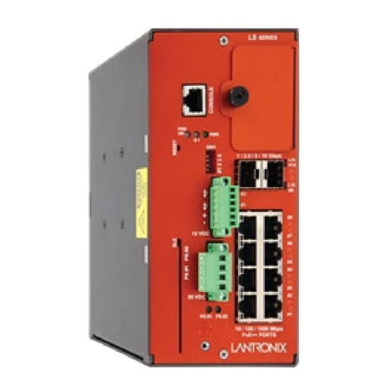
Front Panel
(Note: PHO is currently Disabled by default; do not override until fully supported.)
RESET Button
The RESET button is inset from the front panel. Use a thin object such as a paperclip to depress the button.
Press the front panel RESET button for 1-5 seconds to reset the switch.
Press the front panel RESET button for over 5 seconds to restore the switch to its factory defaults.
33859 Rev. A
①
⓪ Expansion slot/cover (for future use)
SW1 : 4-position DIP Switch:
#1 - Enable/Disable PHO
#2 - Input 1 relay normal state (not active)
②
#3 & 4 - PoE power down selection
③④
L/A : Link Activity LED for SFP++ Port 2)
⑤
⑥
L/A : Link Activity LED for SFP++ Port 1
⑦
DIO1 & DIO2 : Digital Input/Output 1 & 2
⑧
P1 – P8 : 10/100/1000 PoE++ Ports
⑨ ⑩
Ground screw hole
⑪
56 VDC + /- : Terminal connector for dual 56VDC
⑫
⑬
BLE : Bluetooth Low Energy connector
⑭⑮⑯
RESET : System reset button
⑰
CONSOLE Port
https://www.lantronix.com/
*
to PoE Power interlock
P9 & P10: Two 10/5/2.5/1G SFP++ Ports
(SFP++ Port 1 & 2)
PS #1 and PS #2: Power Supply 1 and 2 LEDs
input power
PHO On LED, S1 LED, and P (Power) LED
Page 1 of 6
Advertisement
Table of Contents

Subscribe to Our Youtube Channel
Related Manuals for Lantronix LSS2200-8P


Summary of Contents for Lantronix LSS2200-8P
- Page 1 LSS2200-8P Quick Start Guide The LSS2200-8P is a managed Layer 2+ Gigabit Ethernet switch offering eight (8) 1GBase-T interfaces with full IEEE 802.3bt 90W support, two (2) 10/5/2.5/1GBase-T multi-gigabit SFP+ slots, two (2) programmable Digital Input/Outputs with 12V power output, and one (1) RJ-45 console port. The switch offers 720W total PoE budget for powering LED lighting, high-powered security and surveillance cameras and other IP devices.
- Page 2 Lantronix LSS2200-8P Quick Start Guide LED Summary The RJ-45 ports have two LEDs and the SFP+ ports have one LED to indicate port and/or PoE status. Condition Meaning Left LED green On = Link at 1G, Blinking = Link Activity.
- Page 3 Lantronix LSS2200-8P Quick Start Guide Connecting to the CONSOLE Port The RJ-45 serial port on the switch front panel is used to connect to the switch for out-of-band console configuration. The command line interface can be accessed from a terminal or a PC running a terminal emulation program. The Console port is one of two types of OOB management scenarios.
- Page 4 CAUTION: Always match the PSx input supply to the Power Supply 1 and Power Supply 2 software setting. Mismatching will cause the LSS2200-8P to think it can draw more power from the external supply than it is capable of providing and results could be detrimental.
- Page 5 Lantronix LSS2200-8P Quick Start Guide Connecting to DC Power The front panel terminal block allows connection of one or two supported 56VDC power supplies. 1. Ground the enclosure before you install the terminal block connector into the network switch. 2. Use wire size of 12 to 24 AWG.
- Page 6 Sales Offices: www.lantronix.com/about/contact. © 2022 Lantronix, Inc. All rights reserved. Lantronix is a registered trademark of Lantronix, Inc. in the United States and other countries. All other trademarks and trade names are the property of their respective holders. 33859 Rev. A https://www.lantronix.com/...
Need help?
Do you have a question about the LSS2200-8P and is the answer not in the manual?
Questions and answers