
Related Manuals for trig TY96A


Summary of Contents for trig TY96A
- Page 1 TY96/96A and TY97/97A VHF Radio Installation Manual 01238-00-AJ 26 September 2018 Trig Avionics Limited Heriot Watt Research Park Riccarton, Currie EH14 4AP Scotland, UK Copyright Trig Avionics Limited, 2015...
- Page 2 This page intentionally left blank...
-
Page 3: Table Of Contents
TECHNICAL SPECIFICATIONS ....................4 TY96 VHF R 01226-00-01) ............4 ADIO UMBER TY97 VHF R 01228-00-01) ............4 ADIO UMBER TY96A VHF R 01787-00-01) ............5 ADIO UMBER TY97A VHF R 01789-00-01) ............6 ADIO UMBER ) ..................6 HYSICAL PECIFICATIONS ....................... - Page 4 LCD Dim Point ....................... 21 6.2.13 LCD Brightness Curve ....................21 6.2.14 Single PTT Mode ......................21 POST INSTALLATION CHECKS .................... 22 NORMAL OPERATION ......................23 ..........................23 VERVIEW ..........................23 ISPLAY ......................23 OLUME ______________________ Page ii Trig Avionics Limited...
- Page 5 CONTINUED AIRWORTHINESS .................... 26 ....................26 LEANING THE RONT ANEL LIMITED WARRANTY......................27 ENVIRONMENTAL QUALIFICATION FORMS ............... 28 INSTALLATION DRAWINGS ....................32 WIRING DIAGRAMS ......................34 USB FILE FORMAT ....................... 40 14.1 USB C ......................41 OMPATIBILITY ______________________ Trig Avionics Limited Page iii...
-
Page 7: Preface
TY96 or TY97 VHF and TY96A or TY97A VHF radio. 1.2 Scope This manual applies to the installation of the TY96, TY97 and TY96A, TY97A VHF radio. At the publication date of this manual the software version identifier for the TY96/TY97 is 1.7 and the FPGA version identifier is 1.1. -
Page 8: Introduction
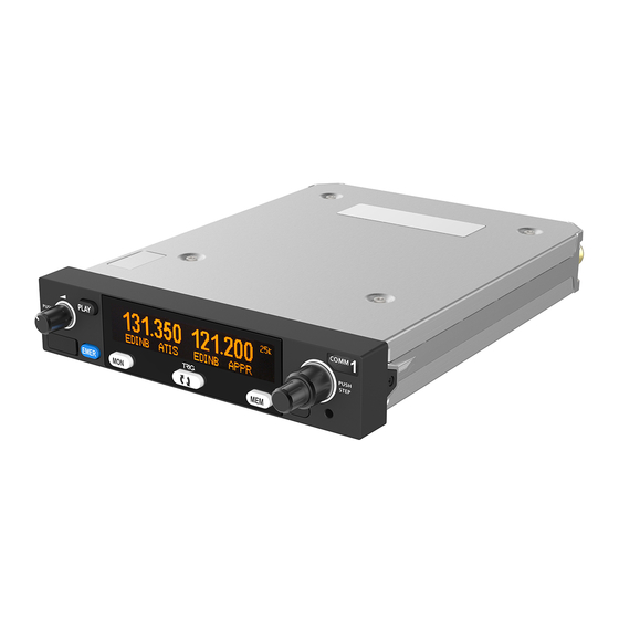
The TY96A and TY97A are variants that use 25 KHz channel spacing and are ED-23C compliant class C (25 kHz offset carrier) VHF radios. The TY96A has a nominal power output of 10 watts, and meets the power output requirements for Class 4. The TY97A has a nominal power output of 16 watts, and meets the power output requirements for Class 3. - Page 9 Audio routing: Intercom, received audio, auxiliary and music inputs, transmitter sidetone Mono audio output A mono audio output designed to connect to an aircraft audio panel with an impedance of 600 ohms. Audio routing: Received audio, transmitter sidetone ______________________ Trig Avionics Limited Page 3...
-
Page 10: Technical Specifications
TY96/96A and TY97/97A VHF Radio Installation Manual 26 September 2018 01238-00 Issue AJ 3. Technical Specifications 3.1 TY96 VHF Radio (Trig Part Number 01226-00-01) Specification Characteristics Compliance ETSO 2C169a Class C, E, H1, H2, 4, 6, ETSO 2C128, TSO C169a Class C, E, 4, 6, TSO C128a... -
Page 11: Ty96A Vhf Radio (Trig Part Number 01787-00-01)
Receiver Sensitivity < 5uV for 6 dB SINAD AGC Characteristic < 6dB variation 5 uV to 100 mV EMF 3.3 TY96A VHF Radio (Trig Part Number 01787-00-01) Specification Characteristics Compliance ETSO 2C169a Class C, 4, ETSO 2C128, TSO C169a Class... -
Page 12: Ty97A Vhf Radio (Trig Part Number 01789-00-01)
TY96/96A and TY97/97A VHF Radio Installation Manual 26 September 2018 01238-00 Issue AJ 3.4 TY97A VHF Radio (Trig Part Number 01789-00-01) Specification Characteristics Compliance ETSO 2C169a Class C, 3, ETSO 2C128, TSO C169a Class C, 3, TSO C128a FCC Identification... -
Page 13: Installation Approval
The VHF radio may be installed only if further evaluation by the user/installer documents an acceptable installation that is approved by the appropriate airworthiness authority. 3.8 Non-ETSO Functions The TY96/TY97/TY96A/TY97A radios contain the following non-ETSO functions: • Two place intercom. -
Page 14: Unit And Accessories Supplied
TY96 VHF Radio 01226-00-01 TY96/TY97 Installation Kit 01472-00 TY96/TY97 Mounting Tray 01368-00 TY96 TY96A and TY97 TY97A Pilots Operating Handbook 01239-00 4.2 TY96A VHF radio Items The TY96A VHF radio includes the following items: Unit Description Part Number TY96A VHF Radio... -
Page 15: Installation Kit
If the aircraft does not have existing mounting provisions you may need to fabricate additional brackets to support the VHF radio tray. Existing wiring provisions from a previously installed radio may be re-used provided it is in satisfactory condition. ______________________ Trig Avionics Limited Page 9... -
Page 16: Installation
• Check that the VHF radio locking mechanism is correctly oriented by unscrewing the locking screw using a 3/32” Allen key. ______________________ Page 10 Trig Avionics Limited... -
Page 17: Cooling Requirements
Aux Audio Input Music Audio Left In Input Music Audio Right In Input Ground Microphone 1 Input Microphone 2 Input Reserved Input Remote Flip-Flop Input Intercom Key Input PTT1 Input PTT2 Input Aircraft Power (DC) ______________________ Trig Avionics Limited Page 11... -
Page 18: Orientation Diagram
These contacts are widely used in avionics installation, and there are many tools available on the market that will reliably crimp them to the wiring. Because the contacts are a MIL standard, there is also a MIL standard for the crimp tool, although other proprietary solutions are available. ______________________ Page 12 Trig Avionics Limited... -
Page 19: Power And Ground Wiring
This may be relevant when replacing a previous mono VHF radio where you wish to utilise the existing wiring and mono headset jacks. 5.4.6 Audio Wiring All wires carrying audio signals should be wired using 22 AWG shielded cable to MIL-C-27500 or ______________________ Trig Avionics Limited Page 13... - Page 20 Connect the cable shields to the mounting tray back plate along with the signal ground connections. Secure the ring crimps to the back plate ground lugs using M2.5 screws and spring washers. Ground lugs (x6) ______________________ Page 14 Trig Avionics Limited...
-
Page 21: Example Wire Harness
If the simultaneous use of two radio units is required then each antenna should be as far apart as practicable for maximum isolation. We would recommend placing one antenna on top and one on the bottom of the airframe. The Transmit Interlock function should also be used in this ______________________ Trig Avionics Limited Page 15... -
Page 22: Antenna Ground Plane
5.5.3 BNC Connection Feed the supplied blind mate BNC connector to the TY96 mounting tray back plate and attach the washer combination in the following order: • Wave washer (p/n 00317-00). • Plain washer (p/n 00241-00). ______________________ Page 16 Trig Avionics Limited... -
Page 23: Interface Details
If this pin is tied low, the intercom function depends on the vox operated squelch. Note: It is possible to combine both the key switch and the vox activation, or to use only one. ______________________ Trig Avionics Limited Page 17... -
Page 24: Auxiliary Audio Input
Audio grounds should be connected together with a fly lead connected to the remaining ground pin. Refer section 5.4 for further wiring considerations. ______________________ Page 18 Trig Avionics Limited... -
Page 25: Installation Setup And Test
• Intercom Squelch • Music Volume • Music Muting The items accessed on the second level of menu are: • Frequency Step Size – not available on TY96A/97A • Auxiliary Input Volume • Auxiliary Input Muting • Sidetone Volume •... -
Page 26: Music Muting
8.33 kHz channels can be disabled to simplify the tuning operation. Note: 8.33 kHz operation is required in some European airspace. The TY96A/TY97A are only capable of operating in a 25 KHz environment. 6.2.6 Auxiliary Input Volume The auxiliary input is a low-fidelity monophonic input intended for nav radio ident inputs and simple annunciators. -
Page 27: Lcd Dim Point
Mic 2. For a retrofit installation, for example when replacing an SL40 radio, a single PTT is shared between the two microphones. Enabling Single PTT mode means that whenever PTT1 is pressed both Mic 1 and Mic 2 audio is sent to the transmitter. ______________________ Trig Avionics Limited Page 21... -
Page 28: Post Installation Checks
Intercom adjustment. If the intercom function is being used, set the listening level and squelch appropriately. Note that the squelch is best adjusted in the normal ambient noise environment, for example with the engine(s) running and developing power. ______________________ Page 22 Trig Avionics Limited... -
Page 29: Normal Operation
25 kHz and 50 kHz channels. Changing the step size does not change the behaviour of the radio, only the tuning knob step size – it helps to quickly tune a frequency. On the TY96A/97A pressing the end of the small knob will always change the channel spacing between 25 KHz and 50 kHz channels. -
Page 30: Mon Button
Note the message on the screen and pass that information to your avionics maintenance organisation. Warning messages will automatically clear if the problem is corrected. If a warning persists, it can be manually cleared by pressing the flip-flop button twice. ______________________ Page 24 Trig Avionics Limited... -
Page 31: Fault Annunciation
FAULT code implies that there is a fault with the VHF radio or the installation. Note the FAULT message shown on the screen and pass that information to your avionics maintenance organisation. ______________________ Trig Avionics Limited Page 25... -
Page 32: Continued Airworthiness
When service is required, a complete performance test should be accomplished following any repair action. Repairs should only be carried out in accordance with Trig Avionics Limited service procedures. 9.1 Cleaning the Front Panel The plastic body and switches should be cleaned with a soft cotton cloth moistened with clean water. -
Page 33: Limited Warranty
Heriot Watt Research Park Riccarton, Edinburgh, EH14 4AP Trig Avionics will not accept or pay for any charges for warranty work performed outside our factory without prior written consent. This warranty applies only to products in normal use. It does not apply to units or circuit boards... -
Page 34: Environmental Qualification Forms
11. Environmental Qualification Forms Nomenclature: TY96 VHF Radio Part Number: 01226-00-xx ETSO: 2C169a, 2C128 Manufacturer: Trig Avionics Limited Address: Heriot Watt Research Park, Edinburgh, Scotland, EH14 4AP Conditions DO-160G Description of Conducted Tests Temperature and Altitude Equipment tested to Categories: A4, C4 Low temperature ground survival 4.5.1... - Page 35 TY96/96A and TY97/97A VHF Radio Installation Manual 26 September 2018 01238-00 Issue AJ Nomenclature: TY96A VHF Radio Part Number: 01787-00-xx ETSO: 2C169a, 2C128 Manufacturer: Trig Avionics Limited Address: Heriot Watt Research Park, Edinburgh, Scotland, EH14 4AP Conditions DO-160G Description of Conducted Tests...
- Page 36 Issue AJ Nomenclature: TY97 VHF Radio Part Number: 01228-00-xx ETSO: 2C169a, 2C128 Manufacturer: Trig Avionics Limited Address: Heriot Watt Research Park, Edinburgh, Scotland, EH14 4AP Conditions DO-160G Description of Conducted Tests Temperature and Altitude Equipment tested to Categories: A4, C4 Low temperature ground survival 4.5.1...
- Page 37 Issue AJ Nomenclature: TY97A VHF Radio Part Number: 01789-00-xx ETSO: 2C169a, 2C128 Manufacturer: Trig Avionics Limited Address: Heriot Watt Research Park, Edinburgh, Scotland, EH14 4AP Conditions DO-160G Description of Conducted Tests Temperature and Altitude Equipment tested to Categories: A4, C4 Low temperature ground survival 4.5.1...
-
Page 38: Installation Drawings
CUT OUT DIMENSIONS FOR BEHIND AIRCRAFT PANEL MOUNT 160.30 mm CUT OUT DIMENSIONS FOR FRONT AIRCRAFT PANEL MOUNT (107) (4.2) CENTER OF GRAVITY (COG) Dimensions in (--) are millimetres, dimensions in [--] are inches. ______________________ Page 32 Trig Avionics Limited... - Page 39 TY96/96A and TY97/97A VHF Radio Installation Manual 26 September 2018 01238-00 Issue AJ ITEM DESCRIPTION TY96 VHF Radio TY96 Mounting Tray TY96 Mounting Tray Back Plate Screw M2.5 x 8mm, pan Pozidriv ______________________ Trig Avionics Limited Page 33...
-
Page 40: Wiring Diagrams
TY96/96A and TY97/97A VHF Radio Installation Manual 26 September 2018 01238-00 Issue AJ 13. Wiring Diagrams Diagram 1: System Interface..............................................35 Diagram 2: Typical standalone interconnect (no audio panel) ....................................36 Diagram 3: Audio panel interconnect ............................................. 37 ______________________ Page 34 Trig Avionics Limited... - Page 41 OUTPUTS AND CONNECTIONS SHOULD BE CONNECTED TO THE AUDIO PANEL AND NOT TY96. COM Antenna RS232 TY96 INPUT USED TO PRELOAD THE WITH FREQUENCIES FROM THE DATABASE BNC Antenna Connector Diagram 1: System Interface ______________________ Trig Avionics Limited Page 35...
- Page 42 MICROPHONE 1 PILOTS MICROPHONE the wiring side (TY96 end) MICROPHONE 2 COPILOTS MICROPHONE GROUND MOUNTING TRAY BACK PLATE COM ANTENNA GROUND BLOCK Diagram 2: Typical standalone interconnect ANTENNA (no audio panel) ______________________ Page 36 Trig Avionics Limited...
- Page 43 The diagram above shows the TX INTERLOCK AND PTT CONNECTIONS TO COM REQUIRED TO PREVENT connector orientation as viewed from BREAKTHROUGH WHEN TUNED TO ADJACENT CHANNELS the wiring side (TY96 end) Diagram 3: Audio panel interconnect ______________________ Trig Avionics Limited Page 37...
- Page 44 DIAGRAM ONLY ILLUSTRATES THE EXPOSED WIRING INSIDE THE SHIELD THE SHIELD TY96 SHOULD BE CONNECTED TO THE GROUND BLOCK SL40 TY96 ALL EXISTING SHIELD CONNECTIONS SHOULD BE CONNECTED TO THE GROUND BLOCK Diagram 4: Connections for existing SL40 wiring replacement ______________________ Page 38 Trig Avionics Limited...
- Page 45 (KY197A end) Pin 15 Pin 1 The diagram above shows the connector orientation as viewed from the wiring side (TY96 end) Diagram 5: Connections for existing KY197A wiring connected to an audio panel ______________________ Trig Avionics Limited Page 39...
-
Page 46: Usb File Format
CSV files can be edited using a simple text editor, or they can be opened by most spreadsheet software. The Trig Com radio database is always loaded from and stored to a file called TRIGCOM.CSV located in the root directory of the USB stick. -
Page 47: Usb Compatibility
Although intended as a generic USB interface, not all memory sticks will work in the TY96/TY97. A Trig branded USB stick is supplied with each radio; the Trig USB stick will work correctly. The Trig USB stick also has a read-only partition that contains a copy of this manual.
Need help?
Do you have a question about the TY96A and is the answer not in the manual?
Questions and answers