Advertisement
Quick Links
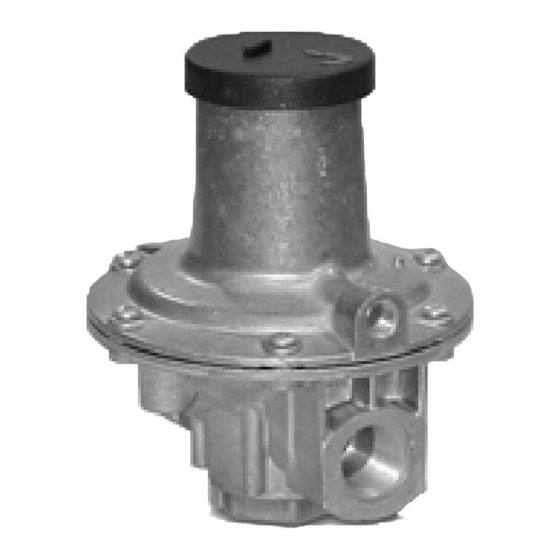
J48K and KC
Commissioning Instructions
OPERATING INSTRUCTIONS
•
Ensure that this product is suitable for the chosen application.
•
Installation, adjustment and maintenance by authorised, trained personnel only.
•
When being fitted to an appliance, refer to the appliance manufacturers instructions.
Warning!
Incorrect installation, adjustment, modification, operation and maintenance may
cause injury or damage.
Read the instructions before use. This control must be installed in accordance with the rules in
force.
J48KC CREEP RELIEF VALVE (A)
1.
From the graph opposite choose the restriction washer that will give the appropriate flow at the
relief pressure required.
2.
Using the templates overleaf, identify the restriction washer required from the selection supplied
with the relief valve.
3.
Introduce the restriction washer to the inlet of the relief valve body and secure using the wire
circlip.
4.
To complete the commissioning follow the instructions below for J48K.
J48K PRESSURE RELIEF VALVE
FITTING RELIEF VALVE INTO PIPEWORK (B)
1.
Remove the plastic protection plugs from inlet and outlet (and breather if applicable).
2.
Ensure that installation pipework is thoroughly clean.
3.
The direction of the gas must be the same as the arrows on the relief valve body.
4.
Install the relief valve into the pipework using a jointing compound approved to national
standards.
FOR PRE-SET RELIEF VALVES
1.
Slowly turn on inlet supply.
SETTING THE RELIEF PRESSURE. (C)
1.
Remove the top cap.
2.
Insert a flat blade screw driver into slot in the end of the spring adjusting screw.
3.
Turn clockwise to increase pressure on loading spring.
4.
Slowly turn on inlet supply. If possible adjust supply pressure to the required relief pressure. (It is
recommended that the relief pressure be set at a minimum of 1.2 times the system working
pressure).
5.
To set the relief valve turn the spring adjusting screw anti-clockwise until the valve starts to
relieve pressure.
6.
Reduce the supply pressure to normal working conditions.
7.
Replace the top cap (and seal if necessary).
IF THE REQUIRED RELIEF PRESSURE CANNOT BE ACHIEVED WITH THE SPRING
FITTED. (D) & (E)
1.
Choose a loading spring from the catalogue that will give the required relief pressure.
2.
Turn spring adjusting screw anti-clockwise (to reduce loading on spring).
3.
Carefully lift protruding end of locking lever just clear of adjusting bush
(octagonal shaped) adjusting bush assembly anti-clockwise until disengaged . The adjusting bush
assembly can then be removed from the top cover.
5.
Remove the loading spring.
6.
Insert the new loading spring.
7.
Screw the top spring holder anti-clockwise to within 10mm of underside of adjusting bush.
8.
Position underside of top spring holder onto loading spring.
9.
Align slots in top spring holder with splines in top cover and push adjusting bush assembly into
top cover as far as possible.
10.
Turn adjusting bush assembly clockwise until locking lever snaps into any of the three locking
castellations in the top cover.
11.
Adjust the relief pressure, as described above, until the required setting is found.
12.
Replace the top cap (and seal if necessary).
, whilst in this position turn
Advertisement

Related Manuals for Elster J48K


Summary of Contents for Elster J48K
- Page 1 Introduce the restriction washer to the inlet of the relief valve body and secure using the wire circlip. To complete the commissioning follow the instructions below for J48K. J48K PRESSURE RELIEF VALVE FITTING RELIEF VALVE INTO PIPEWORK (B) Remove the plastic protection plugs from inlet and outlet (and breather if applicable).
- Page 2 J48K and KC: Commissioning Instructions MAXIMUM RELIEF CAPACITY 10mm 13mm None ¾” 1” 0.01 FLOW RATE (SCMH 0.64sg) SELECTION OF RESTRICTION WASHER Using the graph above choose which size of washer will pass the appropriate flow at the relief pressure required.