Table of Contents
Advertisement
Quick Links
Advertisement
Table of Contents

Related Manuals for WILMS RH 35


Summary of Contents for WILMS RH 35
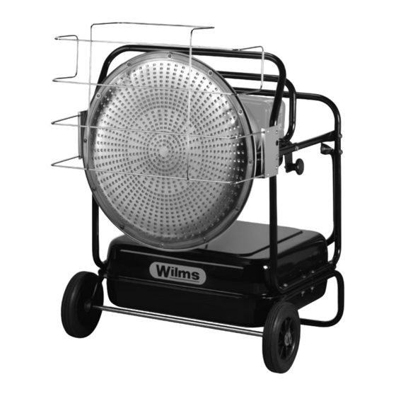
- Page 1 Operating Manual Infrared Oil Heater RH 35 Perfection is our aim.
-
Page 2: Ec Declaration Of Conformity
Structure of the machine Portable air heaters (oil fired with and without heat exchanger) Description: RH 35 is designed, constructed and manufactured in accordance with the above-mentioned directive, EMV directive 2004/30 EEC, the directive for low tension 2014/35 EEC and the directive 2011/65/EC RoHS. - Page 3 Operating Manual Infrared Oil Heater RH 35 ATTENTION! The manufacturer expressly reserves the right to make unannounced technical changes if they serve to improve the performance or the safety standards of the device. 1 of 26...
- Page 4 Assembly Instructions 12 – 13 Starting Procedure Misfire resetting Switching off the heater / Restart 16 – 20 Maintenance RH 35 Possible Malfunctions and Remedies Wiring Diagram RH 35 23 – 26 Spare Part List RH 35 2 of 26...
-
Page 5: Technical Specifications
Technical Specifications Type: RH 35 Heat capacity: 30 kW 25810 k/cal. 102.400 BTU/h Fuel: Heating oil EL / diesel or kersosene Tank capacity: 53 l Voltage: 230 V / 50 Hz Power consumption: 60 W Rated current: 0,4 A Control:... -
Page 6: General Information
The duplication of the manual in total or in parts of it is allowed only with written permission of Hans Wilms GmbH & Co. KG. Reserve: Hans Wilms GmbH & Co. KG reserves the right to make changes and improvements of the product and the operating manual without prior notice. - Page 7 Before operating read very carefully! IMPORTANT ! Infrared Oil Heaters RH 35 shall not be placed in the neighbourhood of explosives or easily flammable materials. Also, they shall not be used within a place where much dust can be stirred such as wood dust, etc.
- Page 8 Infrared heaters with an open combustion chamber (without exhaust pipes) may only be operated to dry out rooms if at least an air volume sufficient for combustion is supplied. The permanent stay of people is prohibited in these rooms. This ban is indicated by signs at the entrances point out.
-
Page 9: Electrical Safety
4. Operating Instructions Important! A possible smoke development at the first operation will disappear after approx. 30 seconds. Although fire can be put out with switch „OFF“, do not pull power cable off outlets as long as operation indicator lamp is on position on. Use only light, filtered fuel oil EL / Diesel or petroleum. - Page 10 Danger of serious burns! Never fill the unit with petrol. Never refill the tank while heater is in operation or hot. Never block air-outlet- or air-suction. Never operate the unit with warm air hose / ducting. Never touch the heater while it is still hot. Never transport the heater with full tank.
-
Page 11: Specifications
5. Specifications RH 35 9 of 26... -
Page 12: Carton Contents
6. Assembly Instructions RH 35 Remove the heater as well as all the packaging material out of the carton. Remember to take the axle out of the styrofoam packaging. Carton-Contents: Screws Screws Nuts Wheels Spacer Washer Front grill 10 of 26... - Page 13 Assembly Instructions RH 35 Push the axle through the frame. Then put first a spacer, a washer, the wheel and another washer on the axle. Secure the wheel with a split pin, picture 5. Fig. 5 Put the heater on the wheel frame and fasten it with two screws (60 mm) and nuts on each side, picture 6.
-
Page 14: Starting Procedure
7. Starting Procedure Filling of the tank: For the best performance of the heater we recommend Heating fuel / Diesel or parafin / cerosene. Never use Bio-Diesel. Never fill the tank during operation or while it is still hot. This might lead to fire or explosion. Fill the tank only on a stable, solid surface. - Page 15 Also check if the unit is connected with a correct socket. Compare with values on the serial plate. RH 35 1. Complete above three steps. 2. Operating switch (20) on position „ON“. The control light is lightning the heater is igniting.
- Page 16 8. Misfire Resetting If the heaters RH 35 are on misfire, the operating switch has to be set to position „AUS – OFF“ first for resetting. After the cause of the malfunction has been eleminated you can restart the unit.
- Page 17 9. Switching off the heater (cooling phase): RH 35 1. Operating switch on „OFF“-position. Combustion stops, cooling process begins for approx. 3 min. 2. After the automatic cooling the fan stops and you can pull the plug. Never pull the plug before the cooling process is finished.
-
Page 18: Long Term Storage
10. Maintenance RH 35 Longterm storage: 1. Remove the tank cap and the drain plug (fig. 17) and empty the tank. 2. Clean the tank by using a rest of the heating fuel. 3. Empty the tank completely. Never mix heating fuel with water, this will result in rost on the inside of the tank. - Page 19 We recommend the following service work: Tank Follow the instructions of longterm storage / tank. Clean the tank every 200 operating hours – resp. when it is necessary. Do not use under any circumstance water for cleaning. Ingnition electrode Clean it every 600 operating hours – resp. exchange it.
- Page 20 Nozzles Nozzles should be cleaned once or replaced during the heating period. Dirty heating fuel can clog the nozzle. In order to clean it, blow air through the nozzle. In order to loosen dirt particles, put the nozzle into diesel or heating fuel first.
- Page 21 Take care that the photocell is replaced to the correct position, refer figure 21. pull out Photocell Fig. 21 Filter The oilfilter should be cleaned at least twice per heating season. When using dirty fuel an earlier cleaning / replacement may be necessary, refer figure 22. Fig.
- Page 22 Automatic temperature control (accessory) When installing a room thermostat, the earth cable (protective conductor yellow-green) must be connected. Fuse exchange Electrical overload causes a defective fuse. Eliminate the cause and replace the defective fuse by unscrewing the safety cap, inserting a new fuse and screwing the safety cap back in.
- Page 23 11. Possible Malfunctions and Remedies Malfunction Cause Remedy Fan does not run. Interruption in the supply line. Check/repair power cord, plug etc. Defective fuse. Replace fuse. Defective contacts. Check/repair resp. Replace electr. connections and contacts. Fan runs but heater does Empty tank.
-
Page 24: Wiring Diagram
12. Wiring Diagram RH 35 Wiring diagram : Power Supply : Switch : Thermostat Bridge : Photocell : Housing Earth : Oil Preheating (optional) : Burner Motor : Plug : Ignition Transformer : Fuel Pump : Plug : Operating Lamp... - Page 25 13. Spare Part List RH 35 Pos. Part.-No. Description Quantity 8400060 Fuel tank 8400061 Fuel gauge assembly 8400062 Tank cap 8400063 Wheel 8400064 Axle 8400065 Wheel frame 8400066 Drain bolt 8400067 Transport handle 8400068 Rear frame 8400070 Frame support 8400071...
- Page 26 Drawing RH 35 24 of 26...
- Page 27 Spare Part List Burner RH 35 Pos. Part.-No. Description Quantity 8805150 Burner cone 8805151 Burner flange 8805152 Diffuser packing 8805153 Nozzle 8805154 Whirl vane 8805155 Electrode cover 8805156 Electrode 8805157 Diffuser 8805152 Nozzle nipple 8805159 Burner base 8805160 Flame monitor...
- Page 28 Drawing Burner RH 35 26 of 26...
Need help?
Do you have a question about the RH 35 and is the answer not in the manual?
Questions and answers