Lantronix LSS2200-8P Install Manual
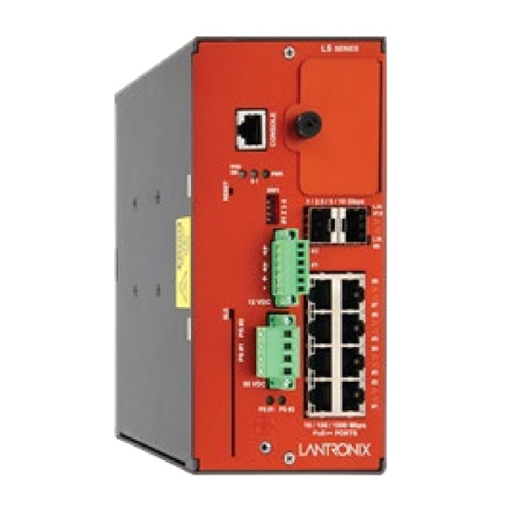
Managed layer 2 gigabit ethernet poe++ switch (8) 10/100/1000base-t ieee 802.3bt + (2) 10g/5g/2.5g/1g sfp+ multi-gig slots
Hide thumbs
Also See for LSS2200-8P:
- Install manual (47 pages) ,
- User manual (8 pages) ,
- Quick start manual (6 pages)

Related Manuals for Lantronix LSS2200-8P


Summary of Contents for Lantronix LSS2200-8P
- Page 1 LSS2200-8P Managed Layer 2 Gigabit Ethernet PoE++ Switch (8) 10/100/1000Base-T IEEE 802.3bt + (2) 10G/5G/2.5G/1G SFP+ Multi-Gig Slots Install Guide Part Number 33860 Revision A October 2022...
- Page 2 LSS2200-8P Install Guide Intellectual Property © 2022 Lantronix, Inc. All rights reserved. No part of the contents of this publication may be transmitted or reproduced in any form or by any means without the written permission of Lantronix. Lantronix is a registered trademark of Lantronix, Inc. in the United States and other countries.
-
Page 3: Table Of Contents
Ordering Information ...............................6 Services (order separately)..........................6 Features ..................................6 PoE Features ................................7 ConsoleFlow Features (Cloud Instance) ........................7 Lantronix Provisioning Manager (LPM) Features ....................7 Specifications ................................8 NFC Flex Stamp Antenna ............................ 10 MobileApp ................................10 3-Axis Accelerometer............................10 IP31 Ingress Protection ............................10 PHO (PoE Hardware Override) ........................... - Page 4 Lantronix LSS2200-8P Install Guide 25172 Weidmὕller PRO MAX 960W 48V 20A ....................28 25160 Power Supply ............................34 Digital I/O (DIO1 & DIO2) Terminal Block ......................36 Connecting to DC Power ............................. 36 Connecting the AC Power Cord .......................... 36 Last Gasp ................................
-
Page 5: Introduction
1. Introduction Product Description The LSS2200-8P is a managed Layer 2+ Gigabit Ethernet switch offering eight (8) 1GBase-T interfaces with full IEEE 802.3bt 90W support, two (2) 10/5/2.5/1GBase-T multi-gigabit SFP+ slots, two (2) programmable Digital Input/Outputs with 12V power output, and one (1) RJ-45 console port. The switch features Near Field Communications (NFC) support for simplified transfer of pre-configuration onto units prior to powering up and dispatching to install sites (coming soon). -
Page 6: Ordering Information
Environment Management (REM) and IoT Gateway products. ConsoleFlow is available as a cloud-based software-as-a-service. Select an annual subscription model. LSS2200-8P Android mobile application provides instant status and access to your MobileApp remote equipment conveniently from your smartphone or tablet. Contact Technical Support for the free download. -
Page 7: Poe Features
Lantronix Provisioning Manager (LPM) Features • Device Discovery: LPM discovers Lantronix IoT gateways and console managers on the local subnet, as well as specified remote subnets, and presents the results for the user to choose devices to perform an action on. -
Page 8: Specifications
Lantronix LSS2200-8P Install Guide Specifications IEE 802.3 (Ethernet), IEEE 802.3u (Fast Ethernet), IEEE 802.3z (1 Gig Ethernet,) Standards IEEE 802.3ae (10GE), IEEE 802.3af/at/bt (PoE), IEEE 802.1Q (VLANs), IEEE 802.1AB (LLDP), IEEE 802.3x (flow control), IEEE 802.1w (Rapid Spanning Tree) • Protocols: CSMA/CD •... - Page 9 Lantronix LSS2200-8P Install Guide 2250 VDC for DI/DOs and 1500 VDC for power output • Input: Vin low max 5.4V Vin high min 7.2V Vin max 34V Digital I/O Isolation Current 66uA typ (Vin 5.4/100K) • Output: Drive current 70mA max...
-
Page 10: Nfc Flex Stamp Antenna
Lantronix LSS2200-8P Install Guide NFC Flex Stamp Antenna The switch provides NFC (Near Field Communication) support for setting configuration parameters without powering the switch. NFC allows simple, repeatable switch configuration with a user-friendly app on an Android-compatible mobile device prior to connecting or powering up the switch. -
Page 11: Applications
Lantronix LSS2200-8P Install Guide Applications • Smart buildings for connection of high power PoE security cameras/WAPs/Private LTE • Powering PoE lighting • Security and Surveillance systems Distributed PoE for Led Lighting: 33860 Rev. A https://www.lantronix.com/... - Page 12 Lantronix LSS2200-8P Install Guide Traffic Management: Distributed PoE for Outdoor Environments: 33860 Rev. A https://www.lantronix.com/...
-
Page 13: Dimensions
Lantronix LSS2200-8P Install Guide Dimensions Safety Information Review the following Cautions and Warnings before starting to install the LSS2200-8P. Note that not all Cautions and Warnings apply to every switch environment and application. Cautions and Warnings Cautions indicate that there is the possibility of poor equipment performance or potential damage to the Warnings equipment. -
Page 14: Electrical Safety Warnings
Lantronix LSS2200-8P Install Guide Warning: Turn any external power source OFF and ensure that the switch is disconnected from the external power source before performing any maintenance. Failure to observe this warning could result in an electrical shock, even death. -
Page 15: High Risk Activities Disclaimer
Nuclear Facilities, Aircraft Navigation or Aircraft Communication Systems, Air Traffic Control, Life Support, or Weapons Systems ("High Risk Activities"). Lantronix and its supplier(s) specifically disclaim any expressed or implied warranty of fitness for such High Risk Activities. -
Page 16: Front Panel
Lantronix LSS2200-8P Install Guide Front Panel ① ⓪ Expansion slot/cover (for future use) SW1 : 4-position DIP Switch: #1 - Enable/Disable PHO to PoE Power interlock #2 - Input 1 relay normal state (not active) ② #3 & 4 - PoE power down selection ③④... -
Page 17: Led Summary
Lantronix LSS2200-8P Install Guide LED Summary Each port has one or more LEDs to indicate port and/or PoE status. The RJ-45 ports have two LEDs and the SFP+ ports have one LED as described and shown below. Condition Meaning Left LED green On = Link at 1G, Blinking = Link Activity. -
Page 18: Mounting Options
Lantronix LSS2200-8P Install Guide Mounting Options Note for all mounting options: Do not block air vents. A minimum of 1 inch clearance is required on all sides of the unit when mounting either vertically or horizontally. Do not stack heat-dissipating objects on top of the unit. -
Page 19: Din Rail Mount
Lantronix LSS2200-8P Install Guide DIN Rail Mount 1. Attach DIN Rail bracket with screws provided and ensure screws are securely tightened prior to mounting. 2. Hook the unit over the DIN rail. 3. Push the bottom of the unit towards the DIN Rail until it snaps into place. -
Page 20: Connecting To The Console Port
RJ45 port of the PC with an Ethernet cable (Cat 5 or better). A dedicated management port is one of two types of OOB management scenarios. Installing SFP+ Modules Note: see the related SFP device manual for important Safety warnings. See the Lantronix Copper SFP page our line of copper SFP transceivers. See the FOA webpage for additional information. -
Page 21: Removing Sfp+ Modules
Lantronix LSS2200-8P Install Guide Removing SFP+ Modules 1. Attach an ESD-preventive wrist strap to your wrist and to a bare metal surface. 2. Disconnect the cable from the SFP+ module. For reattachment, note which cable connector plug is send (TX) and which is receive (RX). -
Page 22: Installation
Lantronix LSS2200-8P Install Guide 2. Installation Package Contents Carefully unpack the contents. Verify that you have received the following items. Contact your sales representative if any item is damaged or missing. Please save the packaging for possible future use. One switch •... -
Page 23: Power Supply Information
Power Input The LSS2200-8P has a 4-pin terminal block that allows for two power inputs. The switch can be powered by a single power supply that meets power input and total power output requirements, or it can be powered by dual power supplies for redundant power. -
Page 24: Setting The Power Supply Values In Switch Software
CAUTION: Always match the PSx input supply to the Power Supply 1 and Power Supply 2 software setting. Mismatching will cause the LSS2200-8P to think it can draw more power from the external supply than it is capable of providing and results could be detrimental. -
Page 25: Single Power Supply Applications
Lantronix LSS2200-8P Install Guide Single Power Supply Applications If using a single power supply, either terminal block input (PS1 or PS2) can be used to power the switch. In the case of power supply failure, there is no backup power, and the switch will cease to operate until power is restored. -
Page 26: Dual Power Supply Applications
Lantronix LSS2200-8P Install Guide Dual Power Supply Applications Same Power Rating on Each Supply If using dual power supplies with the same power rating (wattage), the output voltage of each supply should be set to the same nominal voltage (within 0.5V) for current sharing. If there is a 2V difference in the setting of the power supplies, most (or all) of the power will be sourced from the higher voltage supply. - Page 27 Lantronix LSS2200-8P Install Guide Different Power Ratings If using dual power supplies with different power ratings (wattage), the higher wattage supply must be set as the primary supply (PS2) and must be set at least 2V above the backup or lower wattage supply (PS1). Most or all of the power will be sourced from the primary supply.
-
Page 28: 25172 Weidmὕller Pro Max 960W 48V 20A
Lantronix LSS2200-8P Install Guide 25172 Weidmὕller PRO MAX 960W 48V 20A 25172 Safety Notices and Warnings: This device is only intended for use as described in the operating instructions. WARNING : Any other type of usage is forbidden and can lead to accidents or destruction of the device. - Page 29 Lantronix LSS2200-8P Install Guide Protection class : IP20 Protection class, with PE connection : I Overvoltage category acc. to EN 50178, IEC 62103 : III Pollution degree : 2 Insulation voltage, input–output / input–earth / output–earth : 4 kV AC / 3.5 kV AC / 0.5 kV AC, 1 min Earth discharge current : <...
- Page 30 Lantronix LSS2200-8P Install Guide A. Mounting 25172 The electrical facility should be setup by qualified specialists in compliance with the applicable electrical regulations. All regulations and standards which apply locally should be followed. In particular, this includes the following measures: •...
- Page 31 Lantronix LSS2200-8P Install Guide C. 25172 Mains voltage and fusing The device can be connected to either AC of DC currents. When connecting to a DC system, be sure that the correct poles are connected. This unit is equipped with an internal fuse, so no additional external device protection is required.
- Page 32 Lantronix LSS2200-8P Install Guide F. 25172 Temperature characteristics These power supply units are designed to operate in a temperature range of -25 to +70 °C. A derating of 2.5 %/K takes effect above 60 °C. The unit will shut off if it overheats as a result of excessive environmental conditions. It will then automatically restart after the necessary cool-down period.
- Page 33 Lantronix LSS2200-8P Install Guide 25172 Weidmuller PRO MAX 960W 48V 20A Views The 25172 ships from the factory set to 48V. Set the front panel Adjust screw to the voltage required for your application. See Power Supply Information on page...
-
Page 34: 25160 Power Supply
Lantronix LSS2200-8P Install Guide 25160 Power Supply Hardened DIN Rail Mounted; Input 90-264 VAC, 127-370 VDC. Output: 48 ~ 55 VDC, 10A, 480 Watts. See the 25160 product page. 25160 Features 94% High Efficiency 150% Peak Load Protected against Short Circuit, Overload, Over Voltage, Overheating... - Page 35 Lantronix LSS2200-8P Install Guide 25160 Dimensions Width: 3.37” [85.5 mm] x Depth: 5.06” [128.5 mm] x Height: 5.99” [152.2 mm] 33860 Rev. A https://www.lantronix.com/...
-
Page 36: Digital I/O (Dio1 & Dio2) Terminal Block
Lantronix LSS2200-8P Install Guide Digital I/O (DIO1 & DIO2) Terminal Block The front panel terminal block provides two programmable Digital I/O with 12V power output. Digital I/O can be used for dedicated PHO (PoE Hardware Override) to turn on or off banks of PoE ports in response to an external DI event. -
Page 37: Last Gasp
Lantronix LSS2200-8P Install Guide Last Gasp The Last Gasp circuit provides a short up time during power failure for the CPU to generate SNMP traps or other message events to communicate the impending power failure to external management systems. This short power reserve will last for ~2.3ms under a 45W system load. -
Page 38: Initial Switch Configuration
You can also change the user name or add new user names. See the LSS2200-8P Web User Guide for initial switch configuration, sign in, and web UI operation. See the LSS2200-8P CLI Reference for initial switch configuration, sign in, and command line operation. -
Page 39: Troubleshooting
17. Check the LSS2000-8P product page for possible newer firmware; check the related Release Notes for enhancements or fixes to your problem. Record Device and System Information on page 53. 19. Contact Lantronix Technical Support. LED Troubleshooting The following table provides information to easily troubleshoot problems by taking actions based on the suggested solutions within. -
Page 40: Poe Deployment
802.3af/at "compatible" PDs typically can provide power using only Mode B. • Typical PD Power Requirements 1.8 Watts: Lantronix’ M/GE-ISW-SFP-01-PD (Class 1 Powered Device (0.44 - 3.84 Watts). • 13W: IP Camera, VoIP Phone, Wireless Access Point, Networked Audio. •... -
Page 41: Poe Troubleshooting
2. PoE cables are intended for intrabuilding use only. Connecting your Lantronix switch directly to PoE cables that run outside the building in which the switch is housed will void the user's warranty and could create a fire or shock hazard. -
Page 42: Advanced Steps
Lantronix LSS2200-8P Install Guide 9. If no PoE is available, note that LSS2200-8P per-input power consumption is not limited to the configured budgets for PS1 and PS2. The LSS2200-8P per-input power consumption is dictated by relative input voltage rather than by software configured power budgets. In practice, whichever supply provides higher voltage provides... -
Page 43: Device Label And Box Label
Firmware Version: ____________________ System Date: ______________________________________ 3. Record the LED Status: ________________________________________________________________ ______________________________________________________________________________________ ______________________________________________________________________________________ 4. Provide additional information to your Tech Support Specialist. See the “Troubleshooting” section above. Your Lantronix service contract number: _________________________________________________________ Describe the failure: ________________________________________________________________________ _________________________________________________________________________________________ 33860 Rev. A https://www.lantronix.com/... - Page 44 A description of any action(s) already taken to resolve the problem (e.g., changing mode, rebooting, etc.): _________________________________________________________________________________________ _________________________________________________________________________________________ _________________________________________________________________________________________ The serial and revision numbers of all involved Lantronix products in the network: ________________________ _________________________________________________________________________________________ _________________________________________________________________________________________ A description of your network environment (layout, cable type, etc.): ___________________________________...
-
Page 45: Related Information
Lantronix LSS2200-8P Install Guide 5. Related Information Regulatory Agency Information Emissions: EN55032-2012 FCC Class A; CE; Certifications Immunity: EN55024-2010 Safety: UL62368-1 EN 55035:2017/A11:2020 EN 55032:2015/A11:2020 Class A FCC 47 CFR Part 15 Subpart B Class A EN 55035:2017/A11:2020 EN 55032:2015/A11:2020... -
Page 46: Declaration Of Conformity
Declaration of Conformity Manufacture’s Name : Lantronix, Inc. Manufacture’s Address : 48 Discovery, Suite 250, Irvine, CA 92618 U.S.A. Declares that the products: ILS Series LSS2200-8P Conforms to the following Product Regulations: FCC Part 15 Class A, EN 55032:2012, EN 55024:2010... - Page 47 Irvine, CA 92618, USA Toll Free: 800-526-8766 Phone: 949-453-3990 Fax: 949-453-3995 Technical Support Online: https://www.lantronix.com/technical-support/ Sales Offices For a current list of our domestic and international sales offices, go to the Lantronix web site at www.lantronix.com/about/contact. 33860 Rev. A https://www.lantronix.com/...
Need help?
Do you have a question about the LSS2200-8P and is the answer not in the manual?
Questions and answers