
Related Manuals for Thermo Scientific Partisol 2025i


Summary of Contents for Thermo Scientific Partisol 2025i
- Page 1 Partisol 2025i Sequential Air Sampler/ Partisol 2025i-D Dichotomous Sequential Air Sampler Instruction Manual Part Number 110100-00 14Apr2015...
- Page 2 © 2011 Thermo Fisher Scientific Inc. All rights reserved. Specifications, terms and pricing are subject to change. Not all products are available in all countries. Please consult your local sales representative for details. Thermo Fisher Scientific Air Quality Instruments 27 Forge Parkway Franklin, MA 02038 1-508-520-0430 www.thermo.com/aqi...
- Page 3 WEEE Compliance This product is required to comply with the European Union’s Waste Electrical & Electronic Equipment (WEEE) Directive 2002/96/EC. It is marked with the following symbol: Thermo Fisher Scientific has contracted with one or more recycling/disposal companies in each EU Member State, and this product should be disposed of or recycled through them.
- Page 5 Chapter 1 “Introduction” introduces the user to the advanced features ● of the Partisol 2025i and Partisol 2025i-D and describes the flow and sampling configurations of the system. It also discusses the flow control scheme used in the unit.
- Page 6 “AK Protocol” provides a description of the AK protocol ● commands that can be used to remotely control a Partisol 2025i and 2025i-D using a host device such as a PC or a datalogger. Safety Review the following safety information carefully before using the Sampler.
- Page 7 A properly grounded antistatic wrist strap must be worn while handling any internal component. If an antistatic wrist strap is not available, be sure to touch the instrument chassis before Thermo Fisher Scientific Partisol 2025i and Partisol 2025i-D Instruction Manual...
- Page 8 ▲ Partisol 2025i and Partisol 2025i-D Instruction Manual Thermo Fisher Scientific...
- Page 9 AMTIC web site: http://www.epa.gov/ttn/amtic/pmqa.html, the QC coordinator at any EPA Regional Office, or from the Monitoring and Quality Assurance Group (MD- 14), U.S. EPA, Research Triangle Park, NC 27711. Thermo Fisher Scientific Partisol 2025i and Partisol 2025i-D Instruction Manual...
- Page 10 Chinook Engineering, LLC. VSCC and Very Sharp Cut Cyclone are trademarks of BGI, Inc. Some content of this manual is courtesy of BGI, Inc. Partisol 2025i and Partisol 2025i-D Instruction Manual Thermo Fisher Scientific...
- Page 11 Toll Free U.S. only 1-866-282-0430 U.S., Latin America, and Canada 1-508-520-0430 Europe +31 76 579 5555 China +86 10 8419 3588 Asia Pacific +91 22 27781102 Thermo Fisher Scientific Partisol 2025i and Partisol 2025i-D Instruction Manual...
- Page 12 About This Manual Where to Get Help viii Partisol 2025i and Partisol 2025i-D Instruction Manual Thermo Fisher Scientific...
-
Page 13: Table Of Contents
Removing a Filter Cassette Magazine ..........3-10 Removing Filter Cassettes from a Magazine ........3-11 Post Collection Equilibration ............3-12 Post Collection Weighing ..............3-13 Thermo Fisher Scientific Partisol 2025i and Partisol 2025i-D Instruction Manual... - Page 14 Installing the Metal Piston Friction Ring .......... 3-15 Chapter 4 Partisol 2025i Inlet Conversion ............... 4-1 Partisol 2025i PM2.5 VSCC Components .......... 4-1 Partisol 2025i PM WINS Components ..........4-2 Partisol 2025i PM Components ............4-3 ...
- Page 15 Verifying the Ambient Relative Humidity ........7-6 External Leak Check ................ 7-7 Flow Verification ................7-8 Flow Audit/Verification – Partisol 2025i ........7-9 Flow Audit/Verification – Partisol 2025i-D ........ 7-10 Internal Leak Check ............... 7-11 ...
- Page 16 Flow Calibration Setup ..............9-28 Flow/Flow2 ................. 9-28 Setpoint 1-5 ................9-29 Number of Cal Points ..............9-29 Reset Flow Cal ................9-29 FTS Constant M/B ..............9-30 Partisol 2025i and Partisol 2025i-D Instruction Manual Thermo Fisher Scientific...
- Page 17 Default Gateway ................. 9-49 Host Name ................. 9-49 Network Time Protocol Server ............ 9-50 USB Setup ..................9-50 File Format ................. 9-50 Date Format ................9-51 Thermo Fisher Scientific Partisol 2025i and Partisol 2025i-D Instruction Manual xiii...
- Page 18 USB Port ..................9-69 Export Data Logs ................ 9-69 Export Audit History ..............9-70 Backup Configuration ..............9-71 Restore Configuration ..............9-71 Update Firmware ................ 9-72 Partisol 2025i and Partisol 2025i-D Instruction Manual Thermo Fisher Scientific...
- Page 19 Bypass Shuttle ................9-93 Enable I/O Board ................ 9-93 Display Pixel Test ................9-94 Service Mode ..................9-94 Diagnostics ..................9-94 Program Versions ................ 9-95 Thermo Fisher Scientific Partisol 2025i and Partisol 2025i-D Instruction Manual...
- Page 20 Virtual Impactor Reinstallation ............ 10-16 V-Seals Cleaning and Replacement ..........10-16 V-Seals Cleaning and Replacement in the Partisol 2025i ... 10-17 V-Seals Cleaning and Replacement in the Partisol 2025i-D ..10-21 Particle Trap Filter Exchange ............10-25 ...
- Page 21 Instrument Identification Number ............B-1 Commands ..................B-2 Commands List ................B-3 Measurements ..................B-7 Diagnostics ..................B-10 Datalogging..................B-11 Keys/Display ..................B-18 Thermo Fisher Scientific Partisol 2025i and Partisol 2025i-D Instruction Manual xvii...
- Page 22 Executing RPComm ............... D-5 Creating a New Connection ............D-7 Downloading Stored Data ............D-11 Setting the Storage Pointer Positions .......... D-11 Downloading Data ..............D-12 xviii Partisol 2025i and Partisol 2025i-D Instruction Manual Thermo Fisher Scientific...
- Page 23 Multiple Instruments of the Same Model ........D-27 Multiple Instruments of Different Models ......... D-29 Connecting a Series 1400a and a Partisol 2025i-D ..... D-30 Connecting a Model 2000-FRM and a Partisol 2025i/2025i-D Sampler ..................D-36 ...
- Page 24 Contents Partisol 2025i and Partisol 2025i-D Instruction Manual Thermo Fisher Scientific...
- Page 25 Figures Figure 1–1. Partisol 2025i and 2025i-D Sequential Air Sampler ...... 1-2 Figure 1–2. Partisol 2025i Flow Schematic ............1-7 Figure 1–3. Filter Exchange Mechanism ............1-8 Figure 1–4. Partisol 2025i-D Flow Schematic ..........1-10 Figure 1–5. DIchotomous Flow Configuration ..........1-12 ...
- Page 26 Figure 9–1. Front Panel Display ................9-2 Figure 9–2. Front Panel Pushbuttons ..............9-2 Figure 9–3. Partisol 2025i and 2025i-D Flowchart of Menu-Driven Firmware . 9-5 Figure 10–1. PM Inlet Showing Traditional Inlet (EPA Inlet is Similar) ..10-4 ...
- Page 27 Figure D–13. Control Buttons on the Download Data Screen ......D-13 Figure D–14. Downloaded Filter Data .............. D-15 Figure D–15. Downloaded Interval Data ............D-15 Thermo Fisher Scientific Partisol 2025i and Partisol 2025i-D Instruction Manual xxiii...
- Page 28 Figure D–25. Main Screen ................D-27 Figure D–26. Communications Port Setup Screen Configures for a 1400a Monitor ....................... D-33 Figure D–27. Communication Port Setup Screen ..........D-39 xxiv Partisol 2025i and Partisol 2025i-D Instruction Manual Thermo Fisher Scientific...
- Page 29 Descriptions ...................... 11-21 Table 11–7. I/O Expansion Board (Optional) Connector Pin Descriptions ..11-23 Table 12–1. Partisol 2025i and 2025i-D Replacement Parts ......12-3 Table 12–2. Partisol 2025i and 2025i-D Internal Cables ......... 12-7 Table 12–3. External Device Connection Components ........12-9 ...
- Page 30 Table C–3. Write Coils for 2025i and 2025i-D ..........C-11 Table D–1. Communication Parameters ............D-31 Table E–1. Commands List .................. E-3 Table E–2. Program Register Codes ..............E-13 xxvi Partisol 2025i and Partisol 2025i-D Instruction Manual Thermo Fisher Scientific...
-
Page 31: Chapter 1 Introduction
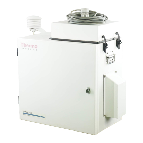
1-10 ● “Specifications” on page 1-15 ● Overview Using a choice of sample inlets, the Partisol 2025i Sequential Air Sampler (Figure 1–1) has the ability to collect PM , PM , PM , and TSP PM. Properly configured collocated samplers can be used to collect and determine... -
Page 32: Figure 1-1. Partisol 2025I And 2025I-D Sequential Air Sampler
The supply and storage magazines are supplied with covers to seal off filter cassettes when not used for sampling. Figure 1–1. Partisol 2025i and 2025i-D Sequential Air Sampler Partisol 2025i and Partisol 2025i-D Instruction Manual Thermo Fisher Scientific... -
Page 33: Inlet System
Introduction Overview Inlet System The Partisol 2025i can be configured to operate with a variety of inlet systems, including the U.S. EPA VSCC or WINS inlet-based reference PM method, and PM , PM (using a Cyclone inlet), PM and TSP (total suspended particulate matter) inlets. -
Page 34: Advanced Features
Introduction Advanced Features Advanced This section lists some of the advanced features of the Partisol 2025i and 2025i-D: Features Partisol 2025i The following is a list of some of the advanced features of the 2025i: Features Automatic filter changing system with a capacity of up to 16 filters per ●... -
Page 35: Partisol 2025I-D Features
● Sampler and includes all U.S. EPA-specified values such as error condition flagging, and average temperatures and pressures. Filter data records also include sampled volume in volumetric and standard terms, Thermo Fisher Scientific Partisol 2025i and Partisol 2025i-D Instruction Manual... -
Page 36: Partisol 2025I Configuration
● life vacuum pump. Data can be retrieved using Ethernet, serial, or USB. ● Partisol 2025i The Partisol 2025i flow schematic provides an overview of the unit’s basic flow and electronic connections (Figure 1–2). The schematic shows an inlet Configuration system consisting of a first-stage inlet that is followed by a down tube and cut device. -
Page 37: Figure 1-2. Partisol 2025I Flow Schematic
For sensitive speciation applications, every second-loaded filter can be a separator, forming a complete seal between filter cassettes contained in the storage magazine. The instrument must be configured for separators prior to use. Thermo Fisher Scientific Partisol 2025i and Partisol 2025i-D Instruction Manual... -
Page 38: Figure 1-3. Filter Exchange Mechanism
The mass flow sensor in the Partisol 2025i is calibrated at a temperature of 0 °C and pressure of 1 Atmosphere (1013.2 millibars or 760 mmHg). The instrument uses the measured ambient temperature and pressure to sample at the correct volumetric flow rate. - Page 39 The current pressure (mmHg) as measured by the pressure transducer in the Sampler’s enclosure. The Partisol 2025i automatically determines the sampled volume in volumetric and standard m³ for each filter exposed, and stores this information internally for later viewing or downloading.
-
Page 40: Partisol 2025I-D Configuration
Introduction Partisol 2025i-D Configuration Partisol 2025i-D The Partisol 2025i-D Dichotomous Sequential Air Sampler consists of two sample flows directed through two separate 47 mm filters that are housed in Configuration the filter platform (Figure 1–4). Figure 1–4. Partisol 2025i-D Flow Schematic Two 47 mm filters are housed in filter cassettes that the user installs with other cassettes in two supply cassette magazines. - Page 41 (1.7 L/min) flow, while the fine particle fraction follows both the minor and major (15 L/min) flow paths. Thermo Fisher Scientific Partisol 2025i and Partisol 2025i-D Instruction Manual 1-11...
-
Page 42: Figure 1-5. Dichotomous Flow Configuration
Three formulas are required for the mass concentration ( g/m³) computation of fine PM (PM ), coarse PM (PM minus PM ), and PM For fine PM: For coarse PM: For PM (in volumetric terms): 1-12 Partisol 2025i and Partisol 2025i-D Instruction Manual Thermo Fisher Scientific... - Page 43 846 g. What is the mass concentration of fine PM, coarse PM and PM For fine PM (using equation 1): For coarse PM (using equation 2): For PM (using equation 3): Thermo Fisher Scientific Partisol 2025i and Partisol 2025i-D Instruction Manual 1-13...
- Page 44 760 mmHg pressure and 25 °C temperature. Flow volumes referenced internally by the Sampler to 0 °C are converted to standard conditions using the following computation: 1-14 Partisol 2025i and Partisol 2025i-D Instruction Manual Thermo Fisher Scientific...
-
Page 45: Specifications
Introduction Specifications Specifications Table 1–1 lists the Partisol 2025i and 2025i-D performance specifications. Table 1–1. Specifications Safety/Electrical Meets the following safety and electrical designations: Designations CE: EN550011 Group 1, Class B (Emissions); EN55082-1 (Immunity); EN611010-1 (Safety) ETL: UL- and CSA-equivalent approval... -
Page 47: Chapter 2 Installation
Partisol 2025i Sampler with PM WINS impactor, VSCC cyclone, or pass through adapter tube: inlet 10 Partisol filter cassettes 3 Filter cassette magazines 3 rainhoods and associated hardware Sample tube Thermo Fisher Scientific Partisol 2025i and Partisol 2025i-D Instruction Manual... -
Page 48: Partisol 2025I-D
9-to-9 pin computer cable Operating manual Quick start guide iPort package RPComm package Partisol 2025i-D Partisol 2025i-D Dichotomous Sampler with virtual impactor: Inlet 20 Partisol filter cassettes 6 Filter cassette magazines 3 rainhoods and associated hardware Sample tube Partisol stand... -
Page 49: Setting Up The Sampler
Standard Hardware Configurations Setting up the Use the following procedure to set up the Sampler. The following instructions apply to both the Partisol 2025i and Partisol 2025i-D Sampler Ambient Samplers. 1. When moving the instrument, be sure to lift the unit by using the two handles. -
Page 50: Figure 2-2. Sampler With A Large Rainhood Installed On The Right Side Panel Of The Unit And A Small Rainhood On Left
Insert the end of the sample tube, with the 5 cm (2 inches) machined section, into the bulkhead of the Sampler. Ensure that the tube is pushed into the enclosure through the final O-ring until it stops. Partisol 2025i and Partisol 2025i-D Instruction Manual Thermo Fisher Scientific... -
Page 51: Figure 2-3. Sample Tube With The Pm Inlet Installed
Locate the two screws on the left side of the enclosure. b. Remove the two screws. Be sure to retain the washers. This will expose two holes. c. Locate the ambient temperature probe assembly in the compilation package. Thermo Fisher Scientific Partisol 2025i and Partisol 2025i-D Instruction Manual... -
Page 52: Figure 2-5. Ambient Temperature Probe Plugged Into The "Ambient Temperature" Connector
Sampler labeled “Ambient Temperature” (Figure 2–5). Figure 2–4. Ambient Temperature Probe Assembly Mounted on the Enclosure Figure 2–5. Ambient Temperature Probe Plugged into the “Ambient Temperature” Connector Partisol 2025i and Partisol 2025i-D Instruction Manual Thermo Fisher Scientific... -
Page 53: Partisol Stand
Sampler. Follow the instructions to install the straight down-tube in the Sampler as provided in “Converting a Partisol 2025i from a PM2.5 Sampler to a PM10 Sampler” on page For PM sampling with the Partisol 2025i, an appropriate PM device, or fractionator, must be installed. -
Page 54: Figure 2-6. Sampler Mounted On Optional Stand
Put this hardware together in accordance with Figure 2–7 and the “Sampler Stand Parts List” that follows. ▲ Figure 2–7. Assembly Information for the Sampler Stand Partisol 2025i and Partisol 2025i-D Instruction Manual Thermo Fisher Scientific... - Page 55 4. Fasten the right and left rails to the legs and top front and back rails with F, G and H hardware (Figure 2–7). 5. Tighten all hardware. 6. Place the Sampler onto the stand and secure using E, G, and H hardware (Figure 2–7). Thermo Fisher Scientific Partisol 2025i and Partisol 2025i-D Instruction Manual...
-
Page 56: Hardware Considerations
10 °C, the pump will continue running until the ambient temperature exceeds 10 °C. After instrument start up when the device is not sampling, the sample pump initiates if the ambient 2-10 Partisol 2025i and Partisol 2025i-D Instruction Manual Thermo Fisher Scientific... -
Page 57: Electronics Compartment Heater Operation
Screen Contrast necessary to change the screen contrast if the instrument is operated at extreme temperatures or lighting conditions. Note The optimal contrast will change with changes in temperature. ▲ Thermo Fisher Scientific Partisol 2025i and Partisol 2025i-D Instruction Manual 2-11... - Page 58 In the Main Menu, choose Service > Screen Contrast. ● SCREEN CONTRAST: CURRENTLY: 50 % SET TO: 60 % ? CHANGE VALUE SAVE VALUE CTRST SSET INSTS STAT 2-12 Partisol 2025i and Partisol 2025i-D Instruction Manual Thermo Fisher Scientific...
- Page 59 “Installing the Metal Piston Friction Ring” on page ▲ Filter Handling and The Partisol 2025i can be configured to sample a wide range of ambient PM sizes, including TSP, PM , PM , and PM . It is important that the...
-
Page 60: Chapter 3 Filter Handling And Exchange
Pallflex TX40 (Teflon coated glass fiber) filters, quartz fiber filters and Teflon material for PM sampling. The Partisol 2025i-D is specifically designed for sampling PM and as such the use of 47-mm diameter, 2 m pore-size Teflon coarse filters must be used for U.S. -
Page 61: Pre-Sampling Filter Weighing
These filter cassettes also are referred to as having “serialized” screens. Close the filter cassette by snapping its top part onto its bottom section. Ensure that the top and bottom pieces of the cassette are pushed completely together. Thermo Fisher Scientific Partisol 2025i and Partisol 2025i-D Instruction Manual... -
Page 62: Figure 3-1. Positioning A 47 Mm Filter On A Balance
As you place each cassette in the magazine, press down to move the piston downward, to make room for the next cassette. Note the order of the filter cassette serial numbers as they are inserted in the magazine. Partisol 2025i and Partisol 2025i-D Instruction Manual Thermo Fisher Scientific... -
Page 63: Figure 3-3. Inserting Filter Cassettes Into A Filter Cassette Magazine
Note The following figures show a clear magazine for informational purposes, however the actual magazines are not clear. ▲ Figure 3–3. Inserting Filter Cassettes into a Filter Cassette Magazine Thermo Fisher Scientific Partisol 2025i and Partisol 2025i-D Instruction Manual... -
Page 64: Preparing The Filter Cassette Magazine
The capped filter cassette magazines should be inserted into the metal transport container (20-004997) (Figure 3–6). The filter cassette magazine’s caps must be secure during transport to avoid contaminating the filters. Collection filters should be transported carefully in the metal Partisol 2025i and Partisol 2025i-D Instruction Manual Thermo Fisher Scientific... -
Page 65: Installing A Filter Cassette Magazine
The sample tube connects to the low flow channel when the enclosure lid is latched. In the software screens on the Partisol 2025i-D, the high flow (15.0 l/min), channel, is shown as “Flow” and the filter in the high flow sampling position is “Filter,”... - Page 66 “low flow” magazines to be installed in the front sampling compartment at the 1.67 L/min flow rate position. When installing the filter cassette magazines into the Partisol 2025i-D, install the rear high flow magazines first and then install the low flow magazines into the front positions of the filter shuttle mechanism.
-
Page 67: Figure 3-7. Positioning The Filter Cassette Magazine Into Its Mounting
Figure 3–10). Storage filter cassette magazine(s) do not have an air pressure supply tube. Figure 3–9. Positioning the Pressurized Air Tube Toward the Air Connector on the Filter Cassette Magazine Thermo Fisher Scientific Partisol 2025i and Partisol 2025i-D Instruction Manual... -
Page 68: Removing A Filter Cassette Magazine
3. Place the orange cap over the open end of the filter cassette magazine to protect its contents during transport. Place the capped magazine into a metal transport container (Figure 3–6). 3-10 Partisol 2025i and Partisol 2025i-D Instruction Manual Thermo Fisher Scientific... -
Page 69: Removing Filter Cassettes From A Magazine
The filter cassette magazine is now ready to be loaded with unused filters. Thermo Fisher Scientific Partisol 2025i and Partisol 2025i-D Instruction Manual 3-11... -
Page 70: Post Collection Equilibration
2. Remove the 47 mm filter from the filter cassette and set the filter in its petri dish. The cassette can then be used to hold other filters once it has been cleaned. 3-12 Partisol 2025i and Partisol 2025i-D Instruction Manual Thermo Fisher Scientific... -
Page 71: Post Collection Weighing
3–14). The average mass reading is the final filter weight, W (g). 5. Return the filter to its petri dish, place the petri dish cover over it and store it for archival purposes. Thermo Fisher Scientific Partisol 2025i and Partisol 2025i-D Instruction Manual 3-13... -
Page 72: Computation Of Mass Concentration
V = the volume drawn through the filter, as obtained from the Sampler. For U.S. EPA PM , this must be volumetric m³. Other sampling standards require that the standard volume be used. The 3-14 Partisol 2025i and Partisol 2025i-D Instruction Manual Thermo Fisher Scientific... -
Page 73: Installing The Metal Piston Friction Ring
Filter Handling and Exchange Installing the Metal Piston Friction Ring Partisol 2025i and Partisol 2025i-D Samplers report volumes in both the actual or standard volume. For 24-hour PM concentration averages to be valid without adjustment for U.S. EPA reporting purposes, the total sampling time must be between 23 and 25 hours, and other requirements must also be met, as referenced in the U.S. -
Page 74: Figure 3-16. Supply Filter Cassette Magazine
Figure 3–17. Supply Filter Cassette Magazine with Bottom Manifold Removed 6. Slide the piston down and out of the bottom of the filter cassette magazine until the groove on the piston is exposed (Figure 3–18). 3-16 Partisol 2025i and Partisol 2025i-D Instruction Manual Thermo Fisher Scientific... -
Page 75: Figure 3-18. Supply Filter Cassette Magazine With Piston Groove Exposed
10. Reinsert the pin into one of the small holes in the bottom of the magazine, through the hole in the manifold, and out the other small hole in the side of the magazine. Push the pin in until it reaches a stop. Thermo Fisher Scientific Partisol 2025i and Partisol 2025i-D Instruction Manual 3-17... -
Page 76: Figure 3-20. Reinstalling The Supply Filter Cassette Magazine Into The Sampler
Note Be sure to remove the metal piston friction ring from all supply filter cassette magazines when operating your Sampler in warmer weather conditions (above 0 °C). ▲ Figure 3–20. Reinstalling the Supply Filter Cassette Magazine into the Sampler 3-18 Partisol 2025i and Partisol 2025i-D Instruction Manual Thermo Fisher Scientific... -
Page 77: Figure 4-1. Vscc, Vscc Adapter, Sample Tube And Pm
Sampler. This section does not apply to the Partisol 2025i-D. When installing a cyclone or WINS impactor in a Partisol 2025i, ensure that the proper adapter is used. The adapter for the VSCC has a groove machined around the upper lip. The adapter for the WINS impactor or other cyclones does not have a machined groove. -
Page 78: Chapter 4 Partisol 2025I Inlet Conversion
WINS Components WINS Adapter Inlet WINS Impactor Sample Tube Figure 4–3. WINS Impactor, WINS Adapter, Sample Tube and PM Inlet Figure 4–4. Sampler with PM Inlet and WINS Impactor Installed Partisol 2025i and Partisol 2025i-D Instruction Manual Thermo Fisher Scientific... -
Page 79: Converting A Partisol 2025I From A Pm Sampler To A Pm Sampler
Sampler equipped with a WINS impactor to a Sampler to a PM Sampler. Sampler 1. Remove the PM inlet from the sample tube by pulling straight upward. Thermo Fisher Scientific Partisol 2025i and Partisol 2025i-D Instruction Manual... -
Page 80: Figure 4-7. Open Top Cover To Access The Wins Impactor And Wins Adapter
Partisol 2025i Inlet Conversion Converting a Partisol 2025i from a PM2.5 Sampler to a PM10 Sampler 2. Unlatch and open the top cover of the Sampler, with the sample tube and PM inlet attached, to gain access to the VSCC or WINS... -
Page 81: Converting A Partisol 2025I From A Pm Sampler To A Pm Sampler
Partisol 2025i Inlet Conversion Converting a Partisol 2025i from a PM10 Sampler to a PM2.5 Sampler and agency. The U.S. EPA requires that these values be 25 °C for temperature and the standard pressure be 760 mmHg. Refer to “Standard Temperature”... -
Page 82: Figure 4-10. Wins Pm Configuration
Partisol 2025i Inlet Conversion Converting a Partisol 2025i from a PM10 Sampler to a PM2.5 Sampler Figure 4–10. WINS PM Configuration Figure 4–11. PM Configuration Partisol 2025i and Partisol 2025i-D Instruction Manual Thermo Fisher Scientific... -
Page 83: Chapter 5 Operational Modes
Wait mode offers the user the choice of entering the Audit or Stop operating modes. Sampling Mode While in the Sampling mode, the Sampler is currently in a user-defined sampling interval. Except in the case of Advanced sampling with Thermo Fisher Scientific Partisol 2025i and Partisol 2025i-D Instruction Manual... -
Page 84: Done Mode
Partisol Operational Modes conditions, the unit will draws ambient air in through its sampling system at the volumetric flow rates specified by the user. For the Partisol 2025i the default flow rate is 16.67 L/min and for the Partisol 2025i-D the default flow is 1.67 L/min for the coarse flow channel and 15 L/min for the fine... -
Page 85: Audit Mode
Calibration menu, scroll to Audit mode and press . At the Audit Mode screen, press to exit the Audit mode, and press confirm the change. Press to resume regular operations. Thermo Fisher Scientific Partisol 2025i and Partisol 2025i-D Instruction Manual... -
Page 86: Operation After A Power Failure
If the hardware is not in the Sampling Operating Mode at the time of ● the power failure, the unit resumes operation in its pre-outage operating mode upon restoration of power. Partisol 2025i and Partisol 2025i-D Instruction Manual Thermo Fisher Scientific... -
Page 87: Chapter 6 Sampler Settings
), low flow (1.67 L/min) channel located in the front sampling coarse compartment. In the software screens on the Partisol 2025i-D, the high flow (15.0 L/min), PM channel, is shown as “Flow” and the filter in the high flow sampling position is “Filter,” and the low flow (1.67 L/min), PMc channel, is “Flow 2”... -
Page 88: Default Sample Setup
Start Time 1 - The Start Time 1 parameter defines the time and date that the Sampler will begin sampling for the desired sample filter. Partisol 2025i and Partisol 2025i-D Instruction Manual Thermo Fisher Scientific... -
Page 89: Advanced Filter Method
The permissible values of the Condition parameter are as follows: ------ Condition not used TEMP Current ambient temperature (°C) PRES Current ambient pressure (mmHg) %RH Current relative humidity (%) WNDSPD Current wind speed (km/h) WNDDIR Current wind direction (deg) Thermo Fisher Scientific Partisol 2025i and Partisol 2025i-D Instruction Manual... -
Page 90: Episodic Sampling Method
Sampler itself is given a duration during which the sampling on an undetermined number of filters will take place. Partisol 2025i and Partisol 2025i-D Instruction Manual Thermo Fisher Scientific... -
Page 91: Default Filter Type
The default flow rate parameter determines the sample flow rate (volumetric L/min). For the Partisol 2025i Sampler, the flow rate is typically 16.7 L/min. The Partisol 2025i-D Sampler uses two flow controllers to maintain the flow through the fine and coarse channels of the sampler. For the Sampler... -
Page 92: Start Time
760. The default setting for Standard Pressure does not have any effect on the volumetric flow rate and actual volume calculations by the unit. This value is used to calculate standard sample volumes. Partisol 2025i and Partisol 2025i-D Instruction Manual Thermo Fisher Scientific... -
Page 93: Filter Fan
The Current date and time parameter are the current local date and time (or other standard time selected by the user) expressed by default as hh:mm and the current local date expressed by default as yyyy/mmm/dd. Thermo Fisher Scientific Partisol 2025i and Partisol 2025i-D Instruction Manual... -
Page 95: Chapter 7 Sampler Operation
8 for EPA verification schedule requirements. The verification procedures are similar for the two types of Partisol Samplers, the Partisol 2025i and Partisol 2025i-D. These procedures are described so they can be used by operators of both Samplers. In specific instances where the procedures need to differentiate between the 2025i and the 2025i-D, the information will be specifically indicated. -
Page 96: Figure 7-1. Loaded Audit Magazine - 2025I And 2025I-D
Press to return to the Audit and Calibration menu. 4. Remove the currently installed storage magazine(s) from the right side of the Sampler and cover with an orange storage cap. Partisol 2025i and Partisol 2025i-D Instruction Manual Thermo Fisher Scientific... -
Page 97: Verifying The Ambient Air Temperature
5. Remove supply magazine(s) from the left side of the filter shuttle mechanism and install on storage side. On the Partisol 2025i-D Sampler, ensure that the rear supply magazine is installed in the rear position on the storage side and the front supply magazine is installed in the front. -
Page 98: Figure 7-2. Removing The Vscc
Audit screen. If the measured and Filter Temp readings are not within ± 2 °C [°C = 5/9 x (°F - 32)] perform the filter temperature calibration procedure. Partisol 2025i and Partisol 2025i-D Instruction Manual Thermo Fisher Scientific... -
Page 99: Partisol Model 2025I-D
If the temperatures measured with the external thermometer and the recorded filter temperatures (Filter Temp and Filter2 Temp) are not within ± 2 °C [°C = 5/9 x (°F - 32)] perform the filter temperature calibration procedure. Thermo Fisher Scientific Partisol 2025i and Partisol 2025i-D Instruction Manual... -
Page 100: Verifying The Ambient Pressure
1. Determine the current ambient relative humidity (%). 2. Verify that the value for Ambient RH in the Audit screen is within ±1.5 percentage points of the measured ambient relative humidity. If Partisol 2025i and Partisol 2025i-D Instruction Manual Thermo Fisher Scientific... -
Page 101: External Leak Check
4. A Pass or Fail message will display at the end of the leak check cycle. The leak check pass criterion is a pressure drop of 25 mmHg or less. Thermo Fisher Scientific Partisol 2025i and Partisol 2025i-D Instruction Manual... -
Page 102: Flow Verification
Sampler (which was used to perform the external leak check) remains in the unit for the flow verification. ▲ While the flow verification procedures are similar for the Partisol 2025i and Partisol 2025i-D, since the Partisol 2025i-D Sampler uses two flow sensors to control the sample flows for the PM... -
Page 103: Flow Audit/Verification - Partisol 2025I
Sampler Operation Sampler Performance Verification Flow Audit/Verification – Use the following procedure to perform a flow audit on the Partisol 2025i: Partisol 2025i 1. Remove the flow audit adapter used during the leak check and install the Streamline Pro on the sample tube (Figure 7–7). -
Page 104: Flow Audit/Verification - Partisol 2025I-D
Use the following procedure to perform a flow audit on the 2025i-D: Partisol 2025i-D The audit procedure is similar to that of the Partisol 2025i single sample version of the Sampler. The main steps of the audit are the same, but must... -
Page 105: Internal Leak Check
2. Scroll to Leak Checks, press , with the cursor at Internal, press The following message displays: MAKE SURE THAT A LEAK CHECK DISK IS IN THE SAMPLE FILTER LOCATION!! Press to begin testing. Thermo Fisher Scientific Partisol 2025i and Partisol 2025i-D Instruction Manual 7-11... -
Page 106: Programming A Sample Run
Install the prepared filter cassette magazines in the filter shuttle mechanisms on the left side of the Partisol 2025i Samplers. A clean, empty storage magazine should be installed on the right side of each filter exchange mechanism. - Page 107 Apply Default Times which automatically applies the default time ● settings. To apply EPA default conditions (midnight-to-midnight, continuous, 24- hour sampling) scroll to Apply EPA Times in the Sample Setup menu, Thermo Fisher Scientific Partisol 2025i and Partisol 2025i-D Instruction Manual 7-13...
- Page 108 Use the pushbuttons as indicated on the screen to set the Cassette2 ID number, and press to save the setting. Press to return to the Sample 1 menu. 7-14 Partisol 2025i and Partisol 2025i-D Instruction Manual Thermo Fisher Scientific...
-
Page 109: Post-Sampling Verification And Data Retrieval
4. Select the desired data records to download and follow the instructions on the instrument display. When complete, remove the USB stick from the Sampler. 5. Press repeatedly to return to the Main Menu. Thermo Fisher Scientific Partisol 2025i and Partisol 2025i-D Instruction Manual 7-15... -
Page 110: Data Download Via Rs-232
, with the cursor at Filter, press , to display the filter records. Filter Record 1 is the oldest record. Filter Record 2 is the most recent record of the 32 maximum filters. 7-16 Partisol 2025i and Partisol 2025i-D Instruction Manual Thermo Fisher Scientific... -
Page 111: Identifying Sampler Status
Status soft key to display any status errors that are currently set. The Status screen displays current staus conditions, but does not display status conditions from previous completed samples. Thermo Fisher Scientific Partisol 2025i and Partisol 2025i-D Instruction Manual 7-17... -
Page 113: Chapter 8 Calibration
For these Calibration procedures, prepare a set of audit magazines consisting of a supply magazine and a clean empty storage magazine. For the Partisol 2025i-D Sampler, two sets of magazines are required. Audit magazine requirements are described in detail in the Audit and Verification section above. - Page 114 4. On the Partisol 2025i-D Sampler, ensure that the rear supply magazine is installed in the rear position on the storage side and the front supply magazine is installed in the front.
-
Page 115: Ambient Air Temperature Calibration
To convert from Atmospheres @ 0 °C to mmHg, multiply by 760. To convert from millibars to mmHg, multiply by 0.75012. To convert from inches Hg @ 32 °F to mmHg, multiply by 25.4. Thermo Fisher Scientific Partisol 2025i and Partisol 2025i-D Instruction Manual... -
Page 116: Filter Pressure Calibration
3. Enter the measured ambient pressure and press . The Sampler automatically adjusts the corresponding offset based upon this input. 4. If the Sampler is a Partisol 2025i-D, repeat these steps to calibrate the filter2 pressure sensor. Filter Compartment Use the following procedure to calibrate the filter compartment temperature. -
Page 117: Filter Temperature Calibration
°C [°C = 5/9 x (°F - 32)] and press save the value. The Sampler automatically adjusts the corresponding offset based upon this input. 5. If the Sampler is a Partisol 2025i-D, Filter2 Temp must also be calibrated. 6. Press... -
Page 118: Flow Calibration
Enter the m and b constants for the FTS sensor(s) into the Sampler. If the Sampler is a Partisol 2025i, enter a single set of constants. If the Sampler is a 2025i-D, enter constants for two flow sensors. To use the FTS as the calibration device, use the following procedure. -
Page 119: Flow Calibraation - Partisol 2025I
Use FTS Constants is set to Yes as described above. 4. Press repeatedly to return to the Main Menu. Scroll to Audit and Calibration and press to display the Audit and Calibration Thermo Fisher Scientific Partisol 2025i and Partisol 2025i-D Instruction Manual... - Page 120 Thermo recommends that these setpoints be used as they are configured for 10% above and below the usual setpoint. For the Partisol 2025i Sampler, the following values are recommended for a three-point calibration of the 16.7 L/min flow rate setpoint: Setpoint 1 (Min Flow): 15.0 L/min (10% below the usual 16.7...
-
Page 121: Flow Calibration - Partisol 2025I-D
2. While in Flow2 Cal Setup screen verify the number of points and set points meet your elected settings. Verify the setup for the high flow channel or ‘Flow’ also matches your elected settings. Thermo Fisher Scientific Partisol 2025i and Partisol 2025i-D Instruction Manual... - Page 122 6. From the Calibration menu select ‘Advance Filter’ to advance the cassettes into the sampling position. 7. Scroll to ‘Flow’ and press enter a. To start the calibration press enter with the cursor in front of ‘Start Calibration’ 8-10 Partisol 2025i and Partisol 2025i-D Instruction Manual Thermo Fisher Scientific...
- Page 123 8. Using the ‘menu’ key escape back to the Calibration menu. Place any two cassettes in the supply magazines (left side) of the filter shuttle Thermo Fisher Scientific Partisol 2025i and Partisol 2025i-D Instruction Manual 8-11...
- Page 124 Install the NIST-traceable volumetric flow meter onto the sample inlet tube after removing the PM10 inlet. Allow about 2 minutes for the flow meter reading and the unit ‘Live measured’ value to stabilize 8-12 Partisol 2025i and Partisol 2025i-D Instruction Manual Thermo Fisher Scientific...
- Page 125 To audit both flows or the ‘Total Flow’ @ 16.7 LPM the ‘slotted’ calibration/audit cassettes is not used and should be replaced with another leak free regular cassette with filter media installed. Thermo Fisher Scientific Partisol 2025i and Partisol 2025i-D Instruction Manual 8-13...
-
Page 127: Chapter 9 Firmware Screen Descriptions
(Figure 9–1). Some menus contain more items than can be displayed at one time. For these menus, use to move the cursor up and down to each item. Thermo Fisher Scientific Partisol 2025i and Partisol 2025i-D Instruction Manual... -
Page 128: Pushbuttons
If the liquid crystal contacts your skin or clothes, wash it off immediately using soap and water. ▲ Pushbuttons The Pushbuttons allow the user to traverse the various screens/menus (Figure 9–2). Figure 9–2. Front Panel Pushbuttons Partisol 2025i and Partisol 2025i-D Instruction Manual Thermo Fisher Scientific... -
Page 129: Soft Keys
“edit soft key prompt” screen will not come up upon entering right-arrow-soft key combinations. All items under the Service menu (including the menu itself) cannot be assigned soft keys. ▲ Thermo Fisher Scientific Partisol 2025i and Partisol 2025i-D Instruction Manual... -
Page 130: Alphanumeric Entry Screen
You can customize the appearance and contents of the Run screen. See “Run Screens” on page 9-75. From the Run screen, the Main Menu can be displayed by pressing Partisol 2025i and Partisol 2025i-D Instruction Manual Thermo Fisher Scientific... -
Page 131: Figure 9-3. Partisol 2025I And 2025I-D Flowchart Of Menu-Driven Firmware
This chapter describes each submenu and screen in detail. Refer to the appropriate sections for more information. Figure 9–3. Partisol 2025i and 2025i-D Flowchart of Menu-Driven Firmware Thermo Fisher Scientific Partisol 2025i and Partisol 2025i-D Instruction Manual... -
Page 132: Power-Up Screen
The word “STOP” on the left of the status bar indicates the Sampler is in “STOP” mode. Other modes appear in the same area of the display. Partisol 2025i and Partisol 2025i-D Instruction Manual Thermo Fisher Scientific... -
Page 133: Custom Run Screens
▲ to move the cursor up and down. ● Press to make a selection. ● Press to return to the Main Menu or to return to the Run ● screen. Thermo Fisher Scientific Partisol 2025i and Partisol 2025i-D Instruction Manual... -
Page 134: Sample Setup Menu
SAMPLE02 2010AUG25 23:00 CTRST SSET INSTS STAT SAMPLE16 2010AUG25 23:00 Auto Populate Auto Populate populates the sample list and calculates the default start time and date once sample 01 is programmed. Partisol 2025i and Partisol 2025i-D Instruction Manual Thermo Fisher Scientific... -
Page 135: Apply Epa Times
Note that the Repeat Time is not shown directly, it is implied by the difference in Start time from sample to sample. In the Main Menu, choose Sample Setup > Sample (1-16). ● Thermo Fisher Scientific Partisol 2025i and Partisol 2025i-D Instruction Manual... -
Page 136: Start
If you set this parameter to Yes, the first filter will be a blank filter and the next filter advanced by the Sampler will be the sampling filter 9-10 Partisol 2025i and Partisol 2025i-D Instruction Manual Thermo Fisher Scientific... -
Page 137: Filter Blank
ID numbers are entered, incremented and edited in the manner described above for Filter ID numbers. The Cassette2 ID screen is used to enter the cassette number for the 2025i- Thermo Fisher Scientific Partisol 2025i and Partisol 2025i-D Instruction Manual 9-11... -
Page 138: Cassette Id
Interval Data - The Sampler writes a new record of interval data every 5 minutes. Each record contains the latest 5-minute average of the filter temperature, ambient temperature, ambient pressure and average flow rate. 9-12 Partisol 2025i and Partisol 2025i-D Instruction Manual Thermo Fisher Scientific... -
Page 139: Filter
Filter Record Status In the Main Menu, choose View Records > Filter. ● FILTER REC. Site1” “ Site2” “ Filt1” 1004“ F2:” 2136“ Cass:” 3225“ C2:” 0“ CTRST SSET INSTS STAT Thermo Fisher Scientific Partisol 2025i and Partisol 2025i-D Instruction Manual 9-13... -
Page 140: Format Of Filter Data Records
-- DATE -- TIME CTRST SSET INSTS STAT FILTER REC. STATUS Status: OK CTRST SSET INSTS STAT Format of Filter Data Each filter data record contains: Records Filter ID (32-character string) 9-14 Partisol 2025i and Partisol 2025i-D Instruction Manual Thermo Fisher Scientific... - Page 141 Minimum Ambient RH (%) Average Ambient RH (%) Maximum Ambient RH (%) Valid Sampling Time (mmmm) Total Sampling Time (mmmm) Filter Identification 2* Cassette Identification 2* Flow Minimum 2 (L/min)* Thermo Fisher Scientific Partisol 2025i and Partisol 2025i-D Instruction Manual 9-15...
-
Page 142: Interval/Srec
The Sampler has the capacity to retain more than 17 days of input data (at one minute logging of 18 data items) before it overwrites the oldest records. 9-16 Partisol 2025i and Partisol 2025i-D Instruction Manual Thermo Fisher Scientific... -
Page 143: Interval/Srec By Record Number
5 minutes. Each record contains the latest 5-minute average of the following: Ambient Temp Filter Temp Ambient Pres Flow Filter2 Temp* Flow2* 2025i-D only Thermo Fisher Scientific Partisol 2025i and Partisol 2025i-D Instruction Manual 9-17... -
Page 144: User/Lrec By Record Number
0000000 TOTAL USERS: 1574 MOVE CURSOR CHANGE VALUE SAVE CTRST SSET INSTS STAT to input the set back number as appropriate and press to save the records. 9-18 Partisol 2025i and Partisol 2025i-D Instruction Manual Thermo Fisher Scientific... -
Page 145: Interval/Srec By Date
SET CURSOR TO MONTHS ACCEPT AS SHOWN CTRST SSET INSTS STAT to select the date and time. Use to change the date and time, and press to display the records. Thermo Fisher Scientific Partisol 2025i and Partisol 2025i-D Instruction Manual 9-19... -
Page 146: Instrument Setup Menu
: Flow = 15.00 L/min; Flow2 = 1.67 L/min IMPORTANT Flow2 Rate and Filter2 Type apply only to the Partisol 2025i-D. ▲ In the Main Menu, choose Instrument Setup > Default Sample Setup. ● 9-20 Partisol 2025i and Partisol 2025i-D Instruction Manual Thermo Fisher Scientific... -
Page 147: Method
Filter Type/Filter2 Type The Filter Type screen allows the user to identify the filter type. The Filter2 Type screen (2025i-D only) is used to identify the filter type for the 2025i-D. Thermo Fisher Scientific Partisol 2025i and Partisol 2025i-D Instruction Manual 9-21... -
Page 148: Filter Type/Filter2 Type
In the Main Menu, choose Instrument Setup > Default Sample Times. ● DEFAULT SAMPLE TIMES: >START TIME 04:00 DURATION 24h 00m REPEAT TIME 24h 00m CTRST SSET INSTS STAT 9-22 Partisol 2025i and Partisol 2025i-D Instruction Manual Thermo Fisher Scientific... -
Page 149: Start Time
The repeat time is reflected in the start time of the next filter. Changing the start time will cause the start time (and stop time) of all the following filters to be updated. Thermo Fisher Scientific Partisol 2025i and Partisol 2025i-D Instruction Manual 9-23... -
Page 150: Trigger Method
The Signal screen allows the user to select signal for the selected trigger. In the Main Menu, choose Instrument Setup > Advanced Trigger > ● Setup Trigger 1-3 > Signal. 9-24 Partisol 2025i and Partisol 2025i-D Instruction Manual Thermo Fisher Scientific... -
Page 151: Minimum And Maximum Trigger
AUTO RUN Average Temperature The Average Temperature screen is used to adjust the average temperature. The default for this parameter is 99 °C indicating that the unit should use Thermo Fisher Scientific Partisol 2025i and Partisol 2025i-D Instruction Manual 9-25... -
Page 152: Standard Temperature
Sampler’s ambient pressure sensor to maintain a constant volumetric flow rate. In the Main Menu, choose Instrument Setup > System Setup > Avg ● Pressure. 9-26 Partisol 2025i and Partisol 2025i-D Instruction Manual Thermo Fisher Scientific... -
Page 153: Standard Pressure
In the Main Menu, choose Instrument Setup > System Setup > Filter ● Fan. FILTER FAN MODE: CURRENTLY: AUTOMATIC SET TO: AUTOMATIC CHANGE VALUE SAVE CTRST SSET INSTS STAT Thermo Fisher Scientific Partisol 2025i and Partisol 2025i-D Instruction Manual 9-27... -
Page 154: Flow Calibration Setup
STAT Flow/Flow2 The Flow Cal Setup menu presents the parameters used to setup flow calibration. In the Main Menu, choose Instrument Setup > Flow Calibration Setup ● > Flow/Flow2. 9-28 Partisol 2025i and Partisol 2025i-D Instruction Manual Thermo Fisher Scientific... -
Page 155: Setpoint 1-5
The Reset Flow Cal menu item is used to reset the flow calibration parameters. In the Main Menu, choose Instrument Setup > Flow Calibration Setup ● > Flow > Reset Flow Cal > press to reset the flow calibration parameters. Thermo Fisher Scientific Partisol 2025i and Partisol 2025i-D Instruction Manual 9-29... -
Page 156: Datalogging
In the Main Menu, choose Instrument Setup > Datalogging. ● DATALOGGING: >SELECT CONTENT COMMIT CONTENT RESET TO DEFAULT CONTENT CONFIGURE DATALOGGING ERASE USER DATA LOG CTRST SSET INSTS STAT ERASE INTERVAL LOG ERASE FILTER LOG 9-30 Partisol 2025i and Partisol 2025i-D Instruction Manual Thermo Fisher Scientific... -
Page 157: Fields 1-32
The selected item is shown by “<--” after it. Note that at this point, pressing indicates that these are proposed changes as opposed to implemented changes. To Thermo Fisher Scientific Partisol 2025i and Partisol 2025i-D Instruction Manual 9-31... -
Page 158: Commit Content
● Select Content > select field > Analog Inputs. ANALOG INPUTS: >NONE ANALOG IN 1 ANALOG IN 2 ANALOG IN 3 ANALOG IN 4 CTRST SSET INSTS STAT 9-32 Partisol 2025i and Partisol 2025i-D Instruction Manual Thermo Fisher Scientific... - Page 159 ELEC TEMP TEMP DLT TEMP2 DLT TEMP DLT MAX TEMP2 DLT MX RELATIVE HUM WIND SPEED WIND DIR WIND SPD AVG WIND VEL WIND VEL AVG WIND DIR AVG Thermo Fisher Scientific Partisol 2025i and Partisol 2025i-D Instruction Manual 9-33...
-
Page 160: Reset To Default Content
TO CONFIRM RESETxx CTRST SSET INSTS STAT CTRST SSET INSTS STAT Configure Datalogging The Configure Datalogging menu is used to configure the datalogging for the currently selected record type. 9-34 Partisol 2025i and Partisol 2025i-D Instruction Manual Thermo Fisher Scientific... -
Page 161: Logging Period Min
Configure Datalogging > Memory Allocation Percent. SET PERCENT USERS: CURRENTLY: SET TO: THIS WILL ERASE ALL LOGS! PRESS TO CONFIRM CHANGE CHANGE VALUE SAVE CTRST SSET INSTS STAT Thermo Fisher Scientific Partisol 2025i and Partisol 2025i-D Instruction Manual 9-35... - Page 162 “Erasing – Please Wait” message to confirm the erasure. In the Main Menu, choose Instrument Setup > Datalogging > Erase ● User Data Log. 9-36 Partisol 2025i and Partisol 2025i-D Instruction Manual Thermo Fisher Scientific...
-
Page 163: Erase User Data Log
Sampler’s data output from this screen. The Site ID2 screen items are used in the same manner as the Site ID1 screen items. Thermo Fisher Scientific Partisol 2025i and Partisol 2025i-D Instruction Manual 9-37... -
Page 164: Communications
The Sampler’s default baud rate is set to 9600 to provide backwards compatibility with the older C-series analyzers. In the Main Menu, choose Instrument Setup > Communications > Serial Settings > Baud Rate. 9-38 Partisol 2025i and Partisol 2025i-D Instruction Manual Thermo Fisher Scientific... -
Page 165: Baud Rate
Selections of 1 and 2 are available, with 1 being the default value. In the Main Menu, choose Instrument Setup > Communications > Serial Settings > Stop Bits. Thermo Fisher Scientific Partisol 2025i and Partisol 2025i-D Instruction Manual 9-39... -
Page 166: Rs-232/Rs-485 Selection
Valid instrument ID numbers are from 0 to 127. In the Main Menu, choose Instrument Setup > Communications > Instrument ID. 9-40 Partisol 2025i and Partisol 2025i-D Instruction Manual Thermo Fisher Scientific... -
Page 167: Communication Protocol
The MODBUS protocol support for the Partisol 2025i and 2025i-D enables the user to read analog values or variables, read the status of the digital outputs of the instrument, and to trigger or simulate the activation of a digital input to the instrument. -
Page 168: Streaming Data Interval
No. If set to Yes, then each streaming data record will start with a time and date stamp indicating when that record was generated. In the Main Menu, choose Service > Communications > Streaming Data Config > Prepend Timestamp. 9-42 Partisol 2025i and Partisol 2025i-D Instruction Manual Thermo Fisher Scientific... -
Page 169: Add Flags
In the Main Menu, choose Instrument Setup > Communications > ● Streaming Data Config > Item # > Measurements. Thermo Fisher Scientific Partisol 2025i and Partisol 2025i-D Instruction Manual 9-43... - Page 170 FILTER2 PRES PUMP PRES AMB PRES AVG FLT PRES AVG FLT2 PRS AVG PMP PRES AVG AMB TMP 5MIN FLT TMP 5MIN FL2 TMP 5MIN FLOW 5MIN FLOW2 5MIN 9-44 Partisol 2025i and Partisol 2025i-D Instruction Manual Thermo Fisher Scientific...
-
Page 171: Table 9-2. Data In Streaming Records - Other Measurements
(none or analog inputs 1-8) that will be included in the streaming record. If the I/O expansion board is not present, Analog Inputs will not be available. Thermo Fisher Scientific Partisol 2025i and Partisol 2025i-D Instruction Manual 9-45... -
Page 172: Table 9-3. Data In Streaming Records - Analog Inputs
FILTER ID FILTER2 ID CASS ID CASS2 ID CTRST SSET INSTS STAT START DATE STOP DATE ELAPSED TIME FS STEP FS STATUS TIME DATE DATE/TIME EXT ALARMS STATUS CODES 9-46 Partisol 2025i and Partisol 2025i-D Instruction Manual Thermo Fisher Scientific... -
Page 173: Table 9-4. Data In Streaming Records - Non-Measurements
Note The instrument power must be cycled after any of these parameters have been changed for the change to take effect. ▲ In the Main Menu, choose Instrument Setup > Communications > TCP/IP Settings. Thermo Fisher Scientific Partisol 2025i and Partisol 2025i-D Instruction Manual 9-47... -
Page 174: Tcp/Ip Settings
In the Main Menu, choose Instrument Setup > Communications > TCP/IP Settings > IP Address. IP ADDRESS: CURRENT: 192.168.1.200 SET TO: 192.168.001.015 MOVE CURSOR CHANGE VALUE SAVE VALUE CTRST SSET INSTS STAT 9-48 Partisol 2025i and Partisol 2025i-D Instruction Manual Thermo Fisher Scientific... -
Page 175: Netmask
The Host Name screen is used to edit the host name. When DHCP is enabled, this name is reported to the DHCP server. In the Main Menu, choose Instrument Setup > Communications > TCP/IP Settings > Host Name. Thermo Fisher Scientific Partisol 2025i and Partisol 2025i-D Instruction Manual 9-49... -
Page 176: Host Name
>FILE FORMAT DATE FORMAT 20110310 FORMAT USB DRIVE CTRST SSET INSTS STAT File Format The File format screen is used to select the format of the export data log files. 9-50 Partisol 2025i and Partisol 2025i-D Instruction Manual Thermo Fisher Scientific... - Page 177 ERASES ALL FILES! ARE YOU SURE?XXX FORMATTING ... PRESS TO CONFIRM PRESS TO CANCEL ERASING - PLEASE WAIT ● CTRST SSET INSTS STAT CTRST SSET INSTS STAT Thermo Fisher Scientific Partisol 2025i and Partisol 2025i-D Instruction Manual 9-51...
-
Page 178: Date/Time
CTRST SSET INSTS STAT Password Menu The Password menu allows the user to configure password protection. If the instrument is “locked,” none of the settings may be changed via the 9-52 Partisol 2025i and Partisol 2025i-D Instruction Manual Thermo Fisher Scientific... -
Page 179: Set Password
Instrument, the instrument reports being in Remote mode. In this mode, Local/Remote Operation the front panel is “locked,” data and settings can be viewed, but not changed using the front panel interface, and the remote “Set” commands are active. Thermo Fisher Scientific Partisol 2025i and Partisol 2025i-D Instruction Manual 9-53... -
Page 180: Unlock Instrument
In the Main Menu, choose Instrument Setup > Password > Change ● Password. ENTER NEW PASSWORD: RANGXXXXXE ABCDEFGHIJKLMN BKSP OPQRSTUVWXYZ PAGE 0123456789 ./- SAVE CTRST SSET INSTS STAT 9-54 Partisol 2025i and Partisol 2025i-D Instruction Manual Thermo Fisher Scientific... -
Page 181: Remove Password
In the Main Menu, choose Audit and Calibration. ● Menu AUDIT AND CALIBRATION: >AUDIT MODE ADVANCE FILTER AUDIT VIEW AUDIT HISTORY CALIBRATION CTRST SSET INSTS STAT LEAK CHECKS Thermo Fisher Scientific Partisol 2025i and Partisol 2025i-D Instruction Manual 9-55... -
Page 182: Audit Mode
In the Main Menu, choose Audit and Calibration > Audit. ● AUDIT: >AMBIENT TEMP -99.9 AMBIENT PRES 0 mmHg FILTER TEMP -99.9 AMBIENT RH FILTER PRES 0 mmHg CTRST SSET INSTS STAT 9-56 Partisol 2025i and Partisol 2025i-D Instruction Manual Thermo Fisher Scientific... -
Page 183: Ambient Temperature
STAT View History The View History screen is used to view history. In the Main Menu, choose Audit and Calibration > Audit > Ambient ● Temperature > View History. Thermo Fisher Scientific Partisol 2025i and Partisol 2025i-D Instruction Manual 9-57... -
Page 184: Calibration
The Calibration menu displays calibration related menu items. Filter2 Pres and Flow2 are used with the 2025i-D only. In the Main Menu, choose Audit and Calibration > Calibration. ● 9-58 Partisol 2025i and Partisol 2025i-D Instruction Manual Thermo Fisher Scientific... -
Page 185: Ambient Pressure
CHANGE VALUE SAVE CTRST SSET INSTS STAT Filter Temperature The Calibrate Filter Temperature screen displays the current averaged values of the filter #1 (high flow filter) temperature (°C). Thermo Fisher Scientific Partisol 2025i and Partisol 2025i-D Instruction Manual 9-59... -
Page 186: Filter Pressure
Flow2 menu items are used in the same manner as the Calibration for Flow menu items. In the Main Menu, choose Audit and Calibration > Calibration > ● Flow. 9-60 Partisol 2025i and Partisol 2025i-D Instruction Manual Thermo Fisher Scientific... -
Page 187: Setpoint 1-5 For Flow
Cal Setup The Cal Setup Flow screen provides parameters for flow calibration setup. In the Main Menu, choose Audit and Calibration > Calibration > Flow ● > Cal Setup. Thermo Fisher Scientific Partisol 2025i and Partisol 2025i-D Instruction Manual 9-61... -
Page 188: Setpoint 1-5
Reset Flow Cal menu item is used to reset the flow calibration to the default value. In the Main Menu, choose Audit and Calibration > Calibration > Flow ● > Cal Setup > Reset Flow Cal. 9-62 Partisol 2025i and Partisol 2025i-D Instruction Manual Thermo Fisher Scientific... -
Page 189: Flow Constant A/B
The Leak Check menu provides access to the internal leak check parameters and the external leak check parameters used in performing leak checks. In the Main Menu, choose Audit and Calibration > Calibration > Leak ● Checks. Thermo Fisher Scientific Partisol 2025i and Partisol 2025i-D Instruction Manual 9-63... -
Page 190: Leak Check Internal
● Checks > External. LEAK CHECK EXTERNAL: MAKE SURE THAT FILTER IS IN PLACE AND LEAK CHECK ADAPTER IS CLOSED!!! PRESS TO BEGIN TESTING CTRST SSET INSTS STAT 9-64 Partisol 2025i and Partisol 2025i-D Instruction Manual Thermo Fisher Scientific... -
Page 191: System Status
The unit stores all status conditions that apply to each exposed filter in the filter data storage buffer. In the Main Menu, choose System Status > Status Codes. ● Thermo Fisher Scientific Partisol 2025i and Partisol 2025i-D Instruction Manual 9-65... -
Page 192: Table 9-5. Status Codes
Filter Temperature 1 Range. The measured temperature of Filter #1 (high flow filter) exceeded the measured ambient temperature by more than 5° C for more than 30 consecutive minutes. 9-66 Partisol 2025i and Partisol 2025i-D Instruction Manual Thermo Fisher Scientific... - Page 193 Blank Filter. Indicates that “sample” was a zero time blank. Hi Wait Flow. This status condition indicates there is flow greater than 1 L/min through the system in Wait mode, when there should be no flow. Thermo Fisher Scientific Partisol 2025i and Partisol 2025i-D Instruction Manual 9-67...
-
Page 194: Alarms
Service mode. Refer to the “Service Mode” on page 9-94 information on the Service mode. ▲ In the Main Menu, choose USB. ● USB: >FRONT USB PORT CTRST SSET INSTS STAT 9-68 Partisol 2025i and Partisol 2025i-D Instruction Manual Thermo Fisher Scientific... -
Page 195: Usb Port
The Export Data Logs screen indicates the status of the process and then displays the name of the file stored on the USB memory device. Thermo Fisher Scientific Partisol 2025i and Partisol 2025i-D Instruction Manual 9-69... - Page 196 The Export Audit History screen is used to export an audit history to a USB memory device. In the Main Menu, choose USB > Front USB Port > Export Audit ● History. EXPORT AUDIT LOG: PROGRESS CTRST SSET INSTS STAT 9-70 Partisol 2025i and Partisol 2025i-D Instruction Manual Thermo Fisher Scientific...
-
Page 197: Backup Configuration
The menu displays the 32 most recent .tbf files in the 2025i directory on the USB memory device. In the Main Menu, choose USB > Front USB Port > Restore ● Configuration. Thermo Fisher Scientific Partisol 2025i and Partisol 2025i-D Instruction Manual 9-71... -
Page 198: Update Firmware
Note The Service mode must be On to access the Service Menu. Refer to “Service Mode” on page 9-94 for information on the Service mode. ▲ In the Main Menu, choose Service. ● 9-72 Partisol 2025i and Partisol 2025i-D Instruction Manual Thermo Fisher Scientific... -
Page 199: Manual Motion
STATUS HALL SENSORS Discrete Actions The Discrete Actions allows the user to choose direct action menu. In the Main Menu, choose Service > Manual Motion > Discrete ● Actions. Thermo Fisher Scientific Partisol 2025i and Partisol 2025i-D Instruction Manual 9-73... -
Page 200: Screen Contrast
Notes The optimal contrast will change with changes in temperature. ▲ The optimal contrast will change from one LCD screen to another. If the LCD screen is replaced, the contrast may need to be reset. ▲ 9-74 Partisol 2025i and Partisol 2025i-D Instruction Manual Thermo Fisher Scientific... -
Page 201: Run Screens
Run screen. This menu allows the user to edit the Run screen title, toggle the Run screen On and Off, specify the number of items to be displayed on the Run screen (1-10), and to assign a parameter to each item. Thermo Fisher Scientific Partisol 2025i and Partisol 2025i-D Instruction Manual 9-75... -
Page 202: Edit Run Screen
Note You cannot scroll through Run screens when a menu screen is displayed. ▲ In the Main Menu, choose Service > Run Screens > Select a Run ● Screen > Enabled. 9-76 Partisol 2025i and Partisol 2025i-D Instruction Manual Thermo Fisher Scientific... -
Page 203: Item Number
In the Main Menu, choose Service > Run Screens > Select a Run ● Screen > Item number. SELECT RUN SCREEN ITEM: >OTHER MEASUREMENTS ANALOG INPUTS NON-MEASUREMENTS OTHER MEASUREMENTS 2 CTRST SSET INSTS STAT Thermo Fisher Scientific Partisol 2025i and Partisol 2025i-D Instruction Manual 9-77... -
Page 204: Table 9-6. Data In Run Screens - Other Measurements
Pressure in mmHg at the filter for the fine channel Filter2 Pressure Pressure in mmHg at the filter for the coarse channel Pump Pressure Pressure at the pump in atmospheres Ambient Pressure Average Average ambient pressure in mmHg 9-78 Partisol 2025i and Partisol 2025i-D Instruction Manual Thermo Fisher Scientific... -
Page 205: Other Measurements 2
The temperature of filter 1 minus the ambient temperature in C Temp Dlt Max The maximum temperature difference of filter 1 over the sample period in C Relative Hum The relative humidity in percent Thermo Fisher Scientific Partisol 2025i and Partisol 2025i-D Instruction Manual 9-79... -
Page 206: Analog Inputs
Run screen. Refer to Item Number described previously. In the Main Menu, choose Service > Run Screens > Select a Run ● Screen > Item number > Non-Measurements. 9-80 Partisol 2025i and Partisol 2025i-D Instruction Manual Thermo Fisher Scientific... -
Page 207: Non-Measurements
In the Main Menu, choose Service > External I/O > Output Relay ● Settings. Thermo Fisher Scientific Partisol 2025i and Partisol 2025i-D Instruction Manual 9-81... -
Page 208: Logic State
In the Main Menu, choose Service > External I/O > Output Relay ● Settings > Select relay 1-10 > Instrument State. CHOOSE SIGNAL TYPE: >ALARMS NON-ALARM CTRST SSET INSTS STAT 9-82 Partisol 2025i and Partisol 2025i-D Instruction Manual Thermo Fisher Scientific... -
Page 209: Alarms
The actual use of these inputs will vary based on the application. Note The digital inputs must be asserted for at least one second for the action to be activated. ▲ Thermo Fisher Scientific Partisol 2025i and Partisol 2025i-D Instruction Manual 9-83... -
Page 210: Digital Input Settings
In the Main Menu, choose Service > External I/O > Digital Input ● Settings > Select relay (1-16) > Instrument Action. 9-84 Partisol 2025i and Partisol 2025i-D Instruction Manual Thermo Fisher Scientific... -
Page 211: Analog Output Configuration (Select Channel)
4 mA. By default this parameter is set to on, and 5% over and under range is allowed for all analog output channels. In the Main Menu, choose Service > External I/O > Analog Output ● Configuration > Allow Over/Under Range. Thermo Fisher Scientific Partisol 2025i and Partisol 2025i-D Instruction Manual 9-85... -
Page 212: Analog Output Configuration (Select Action)
Minimum and Maximum The Minimum Value screen is used to edit the zero (0) to full-scale (100) Value value in percentages for the selected analog output channel. See Table 9–9 9-86 Partisol 2025i and Partisol 2025i-D Instruction Manual Thermo Fisher Scientific... -
Page 213: Table 9-9. Analog Output Zero And Full Scale Values
800 mmHg Filter Pressure Average Filter2 Pressure Average Pump Pressure 0 atm 5 atm Pump Pressure Average Ambient Temperature Filter Temperature -60 °C 60 °C Filter2 Temperature Filter Compartment Temperature Thermo Fisher Scientific Partisol 2025i and Partisol 2025i-D Instruction Manual 9-87... - Page 214 In the Main Menu, choose Service > External I/O > Analog Output ● Configuration > Select Channel > Choose Signal To Output > Choose a signal type. CHOOSE SIGNAL TYPE: >CONCENTRATIONS OTHER MEASUREMENTS ANALOG INPUTS CTRST SSET INSTS STAT 9-88 Partisol 2025i and Partisol 2025i-D Instruction Manual Thermo Fisher Scientific...
-
Page 215: Analog Input Configuration
2-10 table points, and corresponding number of points selected. In the Main Menu, choose Service > External I/O > Analog Input ● Configuration. Thermo Fisher Scientific Partisol 2025i and Partisol 2025i-D Instruction Manual 9-89... -
Page 216: Descriptor
The units may be from 1 to 3 characters in length, and defaults to V (volts). In the Main Menu, choose Service > External I/O > Analog Input ● Configuration > select channel (1-8) > Units. 9-90 Partisol 2025i and Partisol 2025i-D Instruction Manual Thermo Fisher Scientific... -
Page 217: Decimal Places
In the Main Menu, choose Service > External I/O > Analog Input ● Configuration > select channel (1-8) > Table Points. NUMBER OF TABLE POINTS: CURRENTLY: SET TO: 10 ? INC/DEC SAVE VALUE CTRST SSET INSTS STAT Thermo Fisher Scientific Partisol 2025i and Partisol 2025i-D Instruction Manual 9-91... -
Page 218: Volts
1: 0.00 V = 000.0 U and point 2: 10.00 V = 10.0 U, where U is the previously entered unit of measure. In the Main Menu, choose Service > External I/O > Analog Input Configuration > select channel > select point > User Value. 9-92 Partisol 2025i and Partisol 2025i-D Instruction Manual Thermo Fisher Scientific... -
Page 219: Set Serial Number
When an I/O expansion board is removed from the instrument, the Enable I/O Board menu item should be set to “No” to prevent an I/O board alarm from being triggered. Thermo Fisher Scientific Partisol 2025i and Partisol 2025i-D Instruction Manual 9-93... -
Page 220: Display Pixel Test
This menu is useful when troubleshooting the instrument. The analog input readings and analog input voltages are displayed only if the optional I/O expansion board is installed. In the Main Menu, choose Diagnostics. ● 9-94 Partisol 2025i and Partisol 2025i-D Instruction Manual Thermo Fisher Scientific... -
Page 221: Program Versions
Motherboard Voltages The Motherboard Voltages screen (read only) is used to display the voltage readings on the motherboard. In the Main Menu, choose Diagnostics > Voltages > Motherboard. ● Thermo Fisher Scientific Partisol 2025i and Partisol 2025i-D Instruction Manual 9-95... -
Page 222: Interface Board Voltages
The Analog Input Readings screen (read only) displays the eight user-scaled analog input readings (if the I/O expansion board option is installed). In the Main Menu, choose Diagnostics > Analog Input Readings. ● 9-96 Partisol 2025i and Partisol 2025i-D Instruction Manual Thermo Fisher Scientific... -
Page 223: Analog Input Readings
The Relay States screen displays the state of the ten digital outputs and eight solenoid outputs, and allows toggling of the state to either On (1) or Off (0). The relays are restored to their original states upon exiting this screen. Thermo Fisher Scientific Partisol 2025i and Partisol 2025i-D Instruction Manual 9-97... -
Page 224: Test Analog Outputs
“normal” operating mode. In the Main Menu, choose Diagnostics > Test Analog Outputs > ALL, ● Voltage Channel 1–6, or Current Channel 1–6. 9-98 Partisol 2025i and Partisol 2025i-D Instruction Manual Thermo Fisher Scientific... -
Page 225: Set Analog Outputs
The Contact Information screen displays the customer service information. In the Main Menu, choose Diagnostics > Contact Information. ● CONTACT INFORMATION: CALL CENTER: 508-520-0430 WWW.THERMO.COM CTRST SSET INSTS STAT Thermo Fisher Scientific Partisol 2025i and Partisol 2025i-D Instruction Manual 9-99... -
Page 227: Preventive Maintenance
50 °C. Upper and Lower Cassette Seals - Inspect the seals that rest against the filter cassette every time a filter is exchanged. Wipe the seals with a clean Thermo Fisher Scientific Partisol 2025i and Partisol 2025i-D Instruction Manual 10-1... -
Page 228: Partisol 2025I Maintenance Items
Rebuild Kit (59-012071) (one kit is required for each rebuild), or replaced with a new pump. Partisol 2025i In addition to routine maintenance, see the following for Partisol 2025i: Maintenance Items VSCC Cyclone - Clean the VSCC every 30 days of sampling. The cyclone must be cleaned when the unit is not sampling. -
Page 229: Cleaning The Pm
2. Using a Phillips-blade screwdriver, remove the four pan head screws from the top of the top plate. Lift the top plate off the four, threaded, spacer standoffs and set aside. Thermo Fisher Scientific Partisol 2025i and Partisol 2025i-D Instruction Manual 10-3... - Page 230 Dry and reinstall. 4. Using a general-purpose cleaner with a paper towel, clean the top plate deflector cone and internal wall surface of the acceleration assembly. 10-4 Partisol 2025i and Partisol 2025i-D Instruction Manual Thermo Fisher Scientific...
-
Page 231: Lower Collector Assembly Cleaning And Maintenance
1- 1/4-inch OD sample tube. 4. Clean the lower collector assembly’s threads to ensure a tight seal when the two halves are reassembled. Thermo Fisher Scientific Partisol 2025i and Partisol 2025i-D Instruction Manual 10-5... -
Page 232: Pm Inlet Reassembly And Reinstallation
● ● ● Only the PM VSCC is approved for use in a Partisol 2025i for official U.S. EPA PM sampling. Other Cyclones may be approved for PM ) sampling by other agencies. To use the Cyclone fractionator in EPA-designated reference and equipment Samplers, you must clean the fractionator every 30 days of operation. -
Page 233: Cyclone Inlet Cleaning
1. Remove the cyclone from its installed position in the Sampler. The remove of the cyclone is described in the Sampler audit/verification section above. 2. Remove the Partisol 2025i Sampler adapter from the cyclone. Thermo Fisher Scientific Partisol 2025i and Partisol 2025i-D Instruction Manual... -
Page 234: Figure 10-3. Different Adapters Used With The Cyclone Fractionator
Figure 10–3, which shows the two adapters used with the WINS, VSCC, and SCC fractionators in the Partisol 2025i. The adapter used with the WINS impactor and SCC Cyclones (right side of the figure) has a smooth ungrooved surface around the top of the adapter. The adapter used with the VSCC (left side of the figure) has a groove machined into the top section of the adapter. -
Page 235: Wins Pm2.5 Impactor Maintenance
IMPORTANT If you are performing an audit from the Sampling mode and you choose Stop in the Audit Confirmation screen, the Sampler will not resume sampling (after your audit procedures are finished) at the set points Thermo Fisher Scientific Partisol 2025i and Partisol 2025i-D Instruction Manual 10-9... -
Page 236: Figure 10-5. Wins Impactor In Upper Section Of Enclosure
Figure 10–3, which shows the two adapters used with the WINS, VSCC, and SCC fractionators in the Partisol 2025i. The adapter used with the WINS impactor and SCC Cyclones (left side of the figure) has a smooth ungrooved surface around the top of the adapter. The adapter used with the VSCC (right side of the figure) has a groove machined into the top section of the adapter. -
Page 237: Figure 10-6. Upper And Lower Sections Of The Impactor Assembly (On Left And Right Sides Of Figure)
Apply a thin coating of O-ring lubricant onto the O-ring, if necessary. 8. Place a new 37 mm borosilicate, glass-fiber filter (32-004294) onto the bottom of the impactor assembly. Thermo Fisher Scientific Partisol 2025i and Partisol 2025i-D Instruction Manual 10-11... -
Page 238: Wins Impactor Reinstallation
2. Reinsert the WINS impactor into the upper section of the enclosure by pressing downward. 3. Lower the top cover and re-latch it. 4. Perform a system leak check. 10-12 Partisol 2025i and Partisol 2025i-D Instruction Manual Thermo Fisher Scientific... -
Page 239: Virtual Impactor Maintenance
Audit mode. Virtual Impactor Use the following procedures to remove, clean, and reinstall the virtual impactor that is used in the Partisol 2025i-D Sampler. Maintenance Virtual impactor maintenance and performance verification can be performed while in the Stop, Wait, or Sampling modes. If the Sampler is in the Stop Mode, press and select Audit and Calibration >... -
Page 240: Virtual Impactor Cleaning
1. Unscrew the four screws on each corner of the bottom section of the virtual impactor. Separate its probe housing from its base plate (Figure 10–9). Base Plate Nozzle Housing Probe Houseing Figure 10–9. Virtual Impactor Sections 10-14 Partisol 2025i and Partisol 2025i-D Instruction Manual Thermo Fisher Scientific... -
Page 241: Figure 10-10. Interior View Of The Virtual Impactor's Nozzle Housing
A general-purpose cleaner can be used, if necessary. Probe Collector Tube Figure 10–11. Interior View of the Virtual Impactor's Probe Housing Exhaust Tube Figure 10–12. Interior View of the Virtual Impactor's Base Plate Thermo Fisher Scientific Partisol 2025i and Partisol 2025i-D Instruction Manual 10-15... -
Page 242: Virtual Impactor Reinstallation
> Audit and press to turn Off the Audit mode. V-Seals Cleaning As described above, the V-Seals in the Partisol 2025i and Partisol 2025i-D Samplers require periodic maintenance. The V-seals should be checked and Replacement every four weeks and replaced as necessary. In addition, anytime there is a suspected leak in the system that can be attributed to the V-seals, they should be checked and replaced if necessary. -
Page 243: V-Seals Cleaning And Replacement In The Partisol 2025I
Sampler enclosure (Figure 10–14). Note The device is installed with O-rings. Lift and slightly rock the device back and forth to remove it. ▲ Thermo Fisher Scientific Partisol 2025i and Partisol 2025i-D Instruction Manual 10-17... -
Page 244: Figure 10-14. This Example Shows The Vscc Installed In The Sampler
Figure 10–15. Removing the Electronics Cover 5. Remove the side cover of the electronics compartment by removing the four small screws accessible from the main compartment (Figure 10– 16). 10-18 Partisol 2025i and Partisol 2025i-D Instruction Manual Thermo Fisher Scientific... -
Page 245: Figure 10-16. Side Cover
7. Move the plate (with the top head attached) to the side to expose the V-seal in the filter shuttle mechanism (Figure 10–18). Lower V Seal Figure 10–18. Filter Shuttle Mechanism (lower) V-Seal Thermo Fisher Scientific Partisol 2025i and Partisol 2025i-D Instruction Manual 10-19... -
Page 246: Figure 10-19. Top Head (Top) V-Seal
Figure 10–20. Looking Inside Top Cover 10. Replace the top head mounting plate and secure using the four screws. 11. Install the side cover, top cover, and exit cylinder cover. 10-20 Partisol 2025i and Partisol 2025i-D Instruction Manual Thermo Fisher Scientific... -
Page 247: V-Seals Cleaning And Replacement In The Partisol 2025I-D
Partisol 2025i-D 1. Ensure the Sampler is not sampling and is in Stop mode. 2. Unlatch and open the top cover of the Partisol 2025i-D Sampler with the down tube and PM-10 inlet attached to gain access to the virtual... -
Page 248: Figure 10-22. Removing The Virtual Impactor
Exit Cylinder Cover Electronics Cover Figure 10–23. Removing the Electronics Cover 5. Locate the front top head mounting plate and remove the four screws holding it in place (Figure 10–24). 10-22 Partisol 2025i and Partisol 2025i-D Instruction Manual Thermo Fisher Scientific... -
Page 249: Figure 10-24. Top Head Mounting Plate
10–26). The bottom seal is located in the now exposed section of the filter shuttle assembly. Examine both seals for drying and/or cracking or over compression. Replace, if necessary. Bottom V-seal (23-002182) Top V-seal (23-004276) Thermo Fisher Scientific Partisol 2025i and Partisol 2025i-D Instruction Manual 10-23... -
Page 250: Figure 10-26. Top Head (Top) V-Seal
Figure 10–27. Looking Inside Top Cover 11. Install the electronics compartment cover. 12. Replace the virtual impactor and close the top cover. 13. Perform a leak check. 14. Resume normal operation. 10-24 Partisol 2025i and Partisol 2025i-D Instruction Manual Thermo Fisher Scientific... -
Page 251: Particle Trap Filter Exchange
5. Remove the gasket and top disk from the filter stand. Note that the gasket sometimes remains inside the filter manifold. 6. Remove the filter element from the filter stand and install a new element. Thermo Fisher Scientific Partisol 2025i and Partisol 2025i-D Instruction Manual 10-25... -
Page 252: Filter Magazine Maintenance
O-ring on the piston, the large black seal encircling the manifold, or the small black O-ring on the quick disconnect hose barb (attached to the manifold). Obvious damage or signs of wear to the O- 10-26 Partisol 2025i and Partisol 2025i-D Instruction Manual Thermo Fisher Scientific... - Page 253 O-rings and seals, you must reassemble the filter cassette magazine. Use the Reassembly following procedure to reassemble a filter cassette magazine. 1. Slide the piston into the bottom of the magazine tube. Thermo Fisher Scientific Partisol 2025i and Partisol 2025i-D Instruction Manual 10-27...
-
Page 254: Service Locations
Toll Free U.S. only 1-866-282-0430 U.S., Latin America, and Canada 1-508-520-0430 Europe +31 76 579 5555 China +86 10 8419 3588 Asia Pacific +91 22 27781102 10-28 Partisol 2025i and Partisol 2025i-D Instruction Manual Thermo Fisher Scientific... -
Page 255: Troubleshooting
Sampler’s current state. Table 11–1 lists the Diagnostics menu items and describes their function. Refer to the “Diagnostics” on page 9-94 for detailed information about the Diagnostics menu. Thermo Fisher Scientific Partisol 2025i and Partisol 2025i-D Instruction Manual 11-1... -
Page 256: System Status
Guide information and indicates the checks that you should perform if you experience an instrument problem. For additional service assistance, see “Service Locations” on page 11-24. 11-2 Partisol 2025i and Partisol 2025i-D Instruction Manual Thermo Fisher Scientific... -
Page 257: Board-Level Connection Diagram
Check ribbon cable on side of display disconnected board. Board-Level Figure 11–1 Figure 11–2 can be used along with the connector pin descriptions in Table 11–3 through Table 11–7 to troubleshoot board-level Connection Diagram faults. Thermo Fisher Scientific Partisol 2025i and Partisol 2025i-D Instruction Manual 11-3... -
Page 258: Figure 11-1. Board-Level Connection Diagram 2025I
Troubleshooting Board-Level Connection Diagram Figure 11–1. Board-Level Connection Diagram 2025i 11-4 Partisol 2025i and Partisol 2025i-D Instruction Manual Thermo Fisher Scientific... -
Page 259: Figure 11-2. Board-Level Connection Diagram 2025I-D
Troubleshooting Board-Level Connection Diagram Figure 11–2. Board-Level Connection Diagram 2025i-D Thermo Fisher Scientific Partisol 2025i and Partisol 2025i-D Instruction Manual 11-5... -
Page 260: Connector Pin Descriptions
RS485_N to Partisol Interface Board ETHERNET ETX1_P ETX1_N ERX1_P N.C. N.C. ERX1_N N.C. N.C. I/O EXPANSION +15V BOARD +24V +24V RS485_P RS485_N INTF 24V +24V I/O EXPANSION GNDC CONNECTOR PFLT_NC DIGITAL_IN1 DIGITAL_IN2 11-6 Partisol 2025i and Partisol 2025i-D Instruction Manual Thermo Fisher Scientific... - Page 261 DIGITAL_IN15 ANALOG_OUT1 ANALOG_OUT2 GNDA ANALOG_OUT5 GNDA GNDA PFLT_COM PFLT_NO GNDA DIGITAL_IN3 DIGITAL_IN4 DIGITAL_IN6 GNDA DIGITAL_IN9 DIGITAL_IN11 DIGITAL_IN12 DIGITAL_IN14 DIGITAL_IN16 GNDA ANALOG_OUT2 ANALOG_OUT4 GNDA ANALOG_OUT6 USER RS-485/RS- 1A - N.C. Thermo Fisher Scientific Partisol 2025i and Partisol 2025i-D Instruction Manual 11-7...
- Page 262 7B - RS485_OUT_P / RTS 8B - RS485_IN_N / CTS 9B - N.C. USB A&B VBUS_A VBUS_B USB_PORTA_N USB_PORTB_N USB_PORTA_P USB_PORTB_P USB C&D VBUS_C VBUS_D USB_PORTC_N USB_PORTD_N USB_PORTC_P USB_PORTD_P 11-8 Partisol 2025i and Partisol 2025i-D Instruction Manual Thermo Fisher Scientific...
- Page 263 DISABLE DISABLE MCU RESET DISABLE DIGITAL OUTPUT +15V +24V +24V RESET SPI_MISO SPI_MOSI SPI_CS2 SPI_CLK EXTERNAL EXT_RS485_N ACCESSORY EXT_RS485_P +5V 1/2A +5V 1/2A +5V 1/2A N.C. N.C. +24V1/2A +24V1/2A Thermo Fisher Scientific Partisol 2025i and Partisol 2025i-D Instruction Manual 11-9...
- Page 264 Signal Description Designator +24V1/2A +24V1/2A +24V1/2A JTAG N.C. N.C. N.C. N.C. N.C. N.C. N.C. N.C. N.C. 24V MONITOR +24V LCDOUT_CLK LCDOUT_LP LCDOUT_FLM LCDOUT4 LCDOUT0 LCDOUT5 LCDOUT1 LCDOUT6 LCDOUT2 LCDOUT7 LCDOUT3 11-10 Partisol 2025i and Partisol 2025i-D Instruction Manual Thermo Fisher Scientific...
- Page 265 KEYPAD_ROW3 KEYPAD_COL2 KEYPAD_COL1 KEYPAD_COL4 KEYPAD_COL3 +24V +24V AC IN NEUTRAL LIVE EARTH AC 24V POWER NEUTRAL SUPPLY LIVE EARTH AC INTF BOARD NEUTRAL LIVE EARTH DISPLAY LCDOUT_CLK LCDOUT_LP LCDOUT_FLM Thermo Fisher Scientific Partisol 2025i and Partisol 2025i-D Instruction Manual 11-11...
- Page 266 LCDOUT6 LCDOUT7 LCDOUT8 LCDOUT9 LCDOUT10 LCDOUT11 LCDOUT0 LCDOUT1 LCDOUT2 LCDOUT3 LCDOUT4 LCDOUT5 LCDOUT_ONOFF +3.3V +3.3V CONTRAST KEYPAD KEYPAD_ROW1 KEYPAD_ROW2 KEYPAD_ROW3 KEYPAD_ROW4 KEYPAD_COL1 KEYPAD_COL2 KEYPAD_COL3 KEYPAD_COL4 DISPLAY BACKLIGHT +24V 1/4A 11-12 Partisol 2025i and Partisol 2025i-D Instruction Manual Thermo Fisher Scientific...
-
Page 267: Table 11-4. Backplane Board Connector Pin Descriptions
Reference Signal Description Designator MEASUREMENT N.C. INTERFACE BOARD 1 N.C. N.C. N.C. TYPE_CODE0 TYPE_CODE1 FC1_MICROSW LIFT1_UP LIFT1_DN PUSH1_DN PUSH1_UP SHUT_EXT SHUT_RET REV_CODE FC2_MICROSW LIFT2_UP LIFT2_DN PUSH2_DN PUSH2_UP CH_15 N.C. Thermo Fisher Scientific Partisol 2025i and Partisol 2025i-D Instruction Manual 11-13... - Page 268 N.C. N.C. N.C. N.C. MEASUREMENT +24V INTERFACE BOARD 2 STATUS_LAMPS +15VA PGND FILTER_COMP_FANS AGND +5VD DGND 10VA TEMP_FILTER1_SEN TEMP_FILTER2_SEN FCOMP_TEMP_SEN FCOMP_RH_SENSOR AMBTEMP_SENSOR WNDDIR_SENSOR WNDSPD_SENSOR MFS_1 MFS_2 PROP_VALVE1_PWM_P PROP_VALVE1_PWM_N PROP_VALVE2_PWM_P 11-14 Partisol 2025i and Partisol 2025i-D Instruction Manual Thermo Fisher Scientific...
- Page 269 SPARE +24V PWM VALVE 1 PROP_VALVE1_PWM_P PROP_VALVE1_PWM_N SHUTTLE PCB DGND TYPE_CODE0 TYPE_CODE1 FC1_MICROSW LIFT1_UP +5VD DGND LIFT1_DN PUSH1_DN PUSH1_UP SHUT_RET +5VD DGND SHUT_ENT REV_CODE FC2_MICROSW LIFT2_UP +5VD DGND LIFT2_DN Thermo Fisher Scientific Partisol 2025i and Partisol 2025i-D Instruction Manual 11-15...
- Page 270 MFS_1 N.C. AGND +10VA FLOW1 LEAK VALVE +24V FLOW1_LEAK-VALVE AUX 24V +24V SPARE FLOW2 LEAK VALVE +24V FLOW2_LEAK-VALVE MFS 2 MFS_2 N.C. AGND +10VA AC IN AC IN NEUTRAL 11-16 Partisol 2025i and Partisol 2025i-D Instruction Manual Thermo Fisher Scientific...
-
Page 271: Table 11-5. Partisol Measurement Interface Board Connector Pin Descriptions
+5VD Table 11–5. Partisol Measurement Interface Board Connector Pin Descriptions Connector Label Reference Signal Description Designator BACKPLANE BOARD 1 N.C. N.C. N.C. N.C. TYPE_CODE0 TYPE_CODE1 FC1_MICROSW LIFT1_UP LIFT1_DN PUSH1_DN Thermo Fisher Scientific Partisol 2025i and Partisol 2025i-D Instruction Manual 11-17... - Page 272 PUSH2_UP CH_15 N.C. PROP_VALVE1_P PGND PROP_VALVE2_P N.C. N.C. N.C. N.C. N.C. N.C. N.C. N.C. N.C. BACKPLANE BOARD 2 +24V STATUS_LAMPS +15VA PGND FILTER_COMP_FANS AGND +5VD DGND 10VA TEMP_FILTER1_SEN TEMP_FILTER2_SEN 11-18 Partisol 2025i and Partisol 2025i-D Instruction Manual Thermo Fisher Scientific...
- Page 273 PRESS_VENT_VALVE FLOW1_LEAK-VALVE FLOW2_LEAK-VALVE MAG_PRESS_VALVE SHUTTLE_VALVE LIFT_PUSH_VALVE SPARE +24V RS-485 DGND RS485_P RS485_N SPARE 1 SPARE1-1 SPARE1-2 SPARE1-3 DGND POWER SUPPLY +24V_IN PGND +24V OUT +24V_IN PGND STATUS LAMP1 +24V Thermo Fisher Scientific Partisol 2025i and Partisol 2025i-D Instruction Manual 11-19...
- Page 274 HEATER AC HTR_AC_FUSED NEUTRAL EARTH MODEM AC MOD_AC_FUSED NEUTRAL EARTH 12 PIN TEST +5VA EN5V +3.3VA DEN3V +10VA +15VA EN+15V EN-15V REF2.5V DGND JTAG N.C. N.C. N.C. N.C. DGND 11-20 Partisol 2025i and Partisol 2025i-D Instruction Manual Thermo Fisher Scientific...
-
Page 275: Table 11-6. Shuttle/Hall Effect Sensor Distribution Board Connector Pin Descriptions
Table 11–6. Shuttle/Hall Effect Sensor Distribution Board Connector Pin Descriptions Connector Label Reference Signal Description Designator SHUTTLE PCB J100 DGND TYPE_CODE0 TYPE_CODE1 FC1_MICROSW LIFT1_UP +5VD DGND LIFT1_DN PUSH1_DN PUSH1_UP SHUT_RET +5VD DGND SHUT_ENT REV_CODE Thermo Fisher Scientific Partisol 2025i and Partisol 2025i-D Instruction Manual 11-21... - Page 276 PUSHER #1 DN HALL J103 SWITCH PUSH1_DN DGND PUSHER #1 UP HALL J104 SWITCH PUSH1_UP DGND CHANGER #2 MICRO J105 FC2_MICROSW SWITCH DGND LIFT #2 UP/DN HALL J106 SWITCH LIFT2_UP DGND 11-22 Partisol 2025i and Partisol 2025i-D Instruction Manual Thermo Fisher Scientific...
-
Page 277: Table 11-7. I/O Expansion Board (Optional) Connector Pin Descriptions
Analog Voltage Input 3 Ground Analog Voltage Input 4 Analog Voltage Input 5 Analog Voltage Input 6 Ground Analog Voltage Input 7 Analog Voltage Input 8 Ground Current Output Return Ground Thermo Fisher Scientific Partisol 2025i and Partisol 2025i-D Instruction Manual 11-23... - Page 278 Toll Free U.S. only 1-866-282-0430 U.S., Latin America, and Canada 1-508-520-0430 Europe +31 76 579 5555 China +86 10 8419 3588 Asia Pacific +91 22 27781102 11-24 Partisol 2025i and Partisol 2025i-D Instruction Manual Thermo Fisher Scientific...
- Page 279 When the instrument is unplugged, the chassis is not at earth ground. ▲ Thermo Fisher Scientific Partisol 2025i and Partisol 2025i-D Instruction Manual 12-1...
-
Page 280: Servicing
3. Insert the USB memory device with the firmware update into the USB port on the Sampler. 4. Scroll to USB on the Main Menu and press 5. Select the USB port and press 12-2 Partisol 2025i and Partisol 2025i-D Instruction Manual Thermo Fisher Scientific... -
Page 281: Parts Lists
Thermo Fisher Scientific warranty. You may purchase consumable items from Thermo Fisher Scientific by calling our customer service department at 1-866-282-0430. ▲ Table 12–1. Partisol 2025i and 2025i-D Replacement Parts Replacement Parts Part Number Electronics Enclosure w/Processor PCB, 120VAC*... - Page 282 Solid Filter Leak Check/Separator Disk 36-004768 Filter Cassette Screens (10) 59-005147-0010 Filter Cassette Shells (10) 59-005923-0010 Anti-Stick Rings (25) 32-003519 Upper Cassette Seal 22-010318 Lower Cassette Seal 22-005957 Filter Cassette Magazine 55-005569 12-4 Partisol 2025i and Partisol 2025i-D Instruction Manual Thermo Fisher Scientific...
- Page 283 PM-10 Inlet/PM-2.5 SCC Inlet Combo* 59-005944 PM-2.5 SCC* 57-005896 PM-10 Inlet/PM-2.5 VSCC Inlet Combo* 59-008978 PM-2.5 VSCC* 57-008976 PM-10 Inlet/PM-1 SCC Inlet Combo* 59-007942 PM-1 SCC* 10-007742 US TSP Inlet 10-002929 Thermo Fisher Scientific Partisol 2025i and Partisol 2025i-D Instruction Manual 12-5...
- Page 284 Pump Fan Guard (Thomas Pump) 10-009533 Push Connect Fitting, Elbow (1/8NPT Thomas Pump) 32-008756 Pump Assembly, Gast, 120VAC 55-012135-0001 Pump Assembly, Gast, 240VAC 55-012135-0002 Push Connect Fitting, Elbow (1/4NPT Gast Pump) 32-010432 12-6 Partisol 2025i and Partisol 2025i-D Instruction Manual Thermo Fisher Scientific...
-
Page 285: Internal Cables
6-Pin Cable Connector 06-002454 25-Pin Wiring Adapter 06-004521-0025 Internal Cables Table 12–2 lists the internal cables for the Partisol 2025i and 2025i-D. Table 12–2. Partisol 2025i and 2025i-D Internal Cables Part Number Description 101035-00 Measurement Interface Board to 24V Power Supply... - Page 286 AC Switch to Motherboard 110193-00 IEC to Ground (2 required per instrument) 110194-00 Measurement Interface Board to Modem IEC 110288-00 I/O Expansion Board Patch 110289-00 RS-232 Patch 110291-00 USB Patch 12-8 Partisol 2025i and Partisol 2025i-D Instruction Manual Thermo Fisher Scientific...
-
Page 287: External Device Connection Components
● one snap track ● Note Supporting all of the connections on units with the optional I/O expansion board requires: ▲ two DB37 kits ● one DB25 kit ● Thermo Fisher Scientific Partisol 2025i and Partisol 2025i-D Instruction Manual 12-9... -
Page 288: Table 12-4. External Cables
End color codes for 25-pin cables continue for 37-pin cables. VIOLET PINK/GREEN GRAY PINK/RED WHITE PINK/VIOLET PINK LIGHT BLUE LIGHT GREEN LIGHT BLUE/BROWN BLACK/WHITE LIGHT BLUE/RED BROWN/WHITE LIGHT BLUE/VIOLET RED/WHITE LIGHT BLUE/BLACK 12-10 Partisol 2025i and Partisol 2025i-D Instruction Manual Thermo Fisher Scientific... -
Page 289: Filter Log
This filter log can be used to keep track of all important readings associated with each exposed filter. Users are encouraged to make photocopies of the form on the following page or to use a similar format. Thermo Fisher Scientific Partisol 2025i and Partisol 2025i-D Instruction Manual 12-11... - Page 290 Servicing Filter Log 12-12 Partisol 2025i and Partisol 2025i-D Instruction Manual Thermo Fisher Scientific...
-
Page 291: Service Locations
Toll Free U.S. only 1-866-282-0430 U.S., Latin America, and Canada 1-508-520-0430 Europe +31 76 579 5555 China +86 10 8419 3588 Asia Pacific +91 22 27781102 Thermo Fisher Scientific Partisol 2025i and Partisol 2025i-D Instruction Manual 12-13... -
Page 293: Chapter 13 Electronics And I/O Components
Connectors located on the motherboard include: External connectors include: RS-232/485 Communications ● Ethernet Communications ● USB Connector ● Thermo Fisher Scientific Partisol 2025i and Partisol 2025i-D Instruction Manual 13-1... -
Page 294: I/O Expansion Board
Analog input (voltage) ● Digital output (TTL levels) ● Digital input (TTL levels) ● Note The sampler has spare solenoid valve drivers and I/O support for future expansion. ▲ 13-2 Partisol 2025i and Partisol 2025i-D Instruction Manual Thermo Fisher Scientific... -
Page 295: Analog Voltage Outputs
Only two points are necessary for linear inputs, however a larger number of points may be used to approximate non-linear inputs. All voltage inputs have a resolution of 12 bits over the range of 0 to 10 volts. Thermo Fisher Scientific Partisol 2025i and Partisol 2025i-D Instruction Manual 13-3... -
Page 296: Digital Relay Outputs
13-4 Partisol 2025i and Partisol 2025i-D Instruction Manual Thermo Fisher Scientific... -
Page 297: Rs-485 Connection
(set using a DHCP server). Up to three simultaneous connections are allowed per protocol. Any serial port protocols may be accessed over Ethernet in addition to the serial port. Thermo Fisher Scientific Partisol 2025i and Partisol 2025i-D Instruction Manual 13-5... -
Page 298: External Accessory Connector
The USB port is USB 2.0, full speed, 12Mbps; and low speed, 1.5Mbps and is used for interacting with a USB memory device. The USB memory device must be formatted as FAT32. 4 gB or greater is recommended. 13-6 Partisol 2025i and Partisol 2025i-D Instruction Manual Thermo Fisher Scientific... -
Page 299: Appendix A Warranty
(i) normal wear and tear, (ii) accident, disaster or event of force majeure, (iii) misuse, fault or negligence of or by Buyer, (iv) use of the Products in a manner for which Thermo Fisher Scientific Partisol 2025i and Partisol 2025i-D Instruction Manual... - Page 300 OR WRITTEN, WITH RESPECT TO THE PRODUCTS, INCLUDING WITHOUT LIMITATION ALL IMPLIED WARRANTIES OF MERCHANTABILITY OR FITNESS FOR ANY PARTICULAR PURPOSE. SELLER DOES NOT WARRANT THAT THE PRODUCTS ARE ERROR-FREE OR WILL ACCOMPLISH ANY PARTICULAR RESULT. Partisol 2025i and Partisol 2025i-D Instruction Manual Thermo Fisher Scientific...
-
Page 301: Appendix B C-Link Protocol Commands
C-Link Protocol Commands This appendix provides a description of the C-Link protocol commands that can be used to remotely control the Partisol 2025i and 2025i-D Samplers using a host device such as a PC or a datalogger. C-Link protocol may be used over RS-232, RS-485, or Ethernet. C-Link functions can be accessed over Ethernet using TCP/IP port 9880. -
Page 302: Commands
It is important that each time instrument parameters are changed, that this command be sent. If changes are not saved, they will be lost in the event of a power failure. Partisol 2025i and Partisol 2025i-D Instruction Manual Thermo Fisher Scientific... -
Page 303: Commands List
Commands List Table B–1 lists the Partisol 2025i and 2025i-D Sampler C-Link protocol commands. The interface will respond to the associated command strings. Items marked with an “*” apply to the Partisol 2025i-D only. Table B–1. C-Link Protocol Commands Command Description... - Page 304 Reports the value for the actual flow (filter 1) in L/min flow mass Reports the value for the mass flow (filter 1) in L/min flow std Reports the value for the std flow (filter 1) in L/min Partisol 2025i and Partisol 2025i-D Instruction Manual Thermo Fisher Scientific...
- Page 305 Reports/sets memory allocation for short records B-15 me (menu) Simulates pressing menu pushbutton B-18 menutext Displays the text of the menu item where the cursor is currently B-20 positioned Thermo Fisher Scientific Partisol 2025i and Partisol 2025i-D Instruction Manual...
- Page 306 Reports/sets the timezone string for the network time protocol B-29 server Simulates pressing up pushbutton B-18 wind dir Reports the wind direction in degrees (0-360) wind speed Reports the wind speed in km/h Partisol 2025i and Partisol 2025i-D Instruction Manual Thermo Fisher Scientific...
-
Page 307: Measurements
Wait mode and is using the Basic sampling method. Send: flags Receive: flags 00120000 Figure B–1. Flags ambient pres This command reports the current value for the ambient pressure, in mmHg. Send: ambient pres Receive: ambient pres 761.8 Thermo Fisher Scientific Partisol 2025i and Partisol 2025i-D Instruction Manual... - Page 308 This command reports the value for the filter2 pressure in mmHg. Send: filter2 pres Receive: filter2 pres 734.5 filter temp This command reports the value for the filter temperature in degrees C. Send: filter temp Receive: filter temp 18.8 Partisol 2025i and Partisol 2025i-D Instruction Manual Thermo Fisher Scientific...
- Page 309 2.40 wind dir This command reports the wind direction in degrees (0-360). Send: wind dir Receive: wind dir 269 wind speed This command reports the wind speed in km/h. Thermo Fisher Scientific Partisol 2025i and Partisol 2025i-D Instruction Manual...
-
Page 310: Diagnostics
24.1 14.9 4.9 3.2 -3.2 diag volt mib This command reports the diagnostic voltage measurements on the measurement interface board. The sequence of voltages is: Positive 24, B-10 Partisol 2025i and Partisol 2025i-D Instruction Manual Thermo Fisher Scientific... -
Page 311: Datalogging
The following example sets the data treatment for concentrations in lrec as minimum. Send: set data treatment lrec min Receive: set data treatment lrec min ok Thermo Fisher Scientific Partisol 2025i and Partisol 2025i-D Instruction Manual B-11... - Page 312 "flags" command. Send: erec Receive: erec 15:45 03-01-10 flags 130000 lrec srec lrec rec num srec rec num lrxy rec num srxy rec num B-12 Partisol 2025i and Partisol 2025i-D Instruction Manual Thermo Fisher Scientific...
- Page 313 These commands set the output format for lrecs and srecs, and erec data, according to Table B–2. The following example sets the lrec output format to ASCII with text. Send: set lrec format 1 Receive: set lrec format 1 ok Thermo Fisher Scientific Partisol 2025i and Partisol 2025i-D Instruction Manual B-13...
-
Page 314: Table B-2. Record Output Formats
= | 1 | 5 | 15 | 30 | 60 | These commands set the lrecs and srecs logging period to value in minutes. The following example sets the lrec logging period to 15 minutes. B-14 Partisol 2025i and Partisol 2025i-D Instruction Manual Thermo Fisher Scientific... - Page 315 For more information on how to edit the scratch pad, see the “sp field” command. The following example copies the current list in scratch pad into the lrecs list. Thermo Fisher Scientific Partisol 2025i and Partisol 2025i-D Instruction Manual B-15...
- Page 316 “set copy sp to lrec”, “set copy sp to srec”, or “set copy sp to stream” commands. Send: set sp field 1 5 Receive: set sp field 1 5 ok B-16 Partisol 2025i and Partisol 2025i-D Instruction Manual Thermo Fisher Scientific...
-
Page 317: Table B-3. Stream Time Values
Attaches time stamp to streaming data string frec This command retrieves the most recent filter record. If there is no data, the command returns “NO DATA”. Send: frec Receive: frec NO DATA Thermo Fisher Scientific Partisol 2025i and Partisol 2025i-D Instruction Manual B-17... - Page 318 = | do | down | en | enter | he | help | le | left | me | menu | ri | right | ru | run | up | 1 | 2 | 3 | 4 | B-18 Partisol 2025i and Partisol 2025i-D Instruction Manual Thermo Fisher Scientific...
-
Page 319: Keys/Display
4-bit-per-pixel gray-scale image. Also note that BMP files are upside down relative to this data, i.e. the top display line is the last line in the BMP. Thermo Fisher Scientific Partisol 2025i and Partisol 2025i-D Instruction Manual B-19... -
Page 320: Hardware Configuration
This command sets the screen’s level of contrast, according to Table B–4 The following example sets the contrast level to 50%. Send: set contrast 10 Receive: set contrast 10 ok Table B–4. Contrast Levels Contrast Level Level B-20 Partisol 2025i and Partisol 2025i-D Instruction Manual Thermo Fisher Scientific... - Page 321 Send: set save params Receive: set save params ok time This command reports the current time (24-hour time). The following example reports that the internal time is 2:15:30 pm. Thermo Fisher Scientific Partisol 2025i and Partisol 2025i-D Instruction Manual B-21...
-
Page 322: Communications Configuration
Note This command cannot be used when DHCP is on. Refer to the DHCP command that follows for additional information. ▲ Send: set addr gw 192.168.1.1 Receive: set addr gw 192.168.1.1 ok B-22 Partisol 2025i and Partisol 2025i-D Instruction Manual Thermo Fisher Scientific... - Page 323 This command sets the network time protocol server address, where address consists of four numbers ranging from 0-255 inclusive, separated by “.”. Send: set addr ntp 10.209.43.237 Receive: set addr ntp 10.209.43.237 ok Thermo Fisher Scientific Partisol 2025i and Partisol 2025i-D Instruction Manual B-23...
- Page 324 Until you cycle the power, the address assigned by the DHCP server will still be used and reported as the current address. ▲ B-24 Partisol 2025i and Partisol 2025i-D Instruction Manual Thermo Fisher Scientific...
-
Page 325: Table B-5. Reply Termination Formats
This command returns “bad cmd” if no host name has been set. Send: set host name analyzer01 Receive: set host name analyzer01 ok instr name This command reports the instrument name. Thermo Fisher Scientific Partisol 2025i and Partisol 2025i-D Instruction Manual B-25... - Page 326 “ok” as if the command has been accepted and acted upon, but it will not change the instrument lock status (this is for compatibility with systems expecting and “ok” response). B-26 Partisol 2025i and Partisol 2025i-D Instruction Manual Thermo Fisher Scientific...
-
Page 327: Table B-6. Allow Mode Command Values
The following example sets the instrument to power up in remote/locked mode. Send: set power up mode 1 Receive: set power up mode 1 ok Thermo Fisher Scientific Partisol 2025i and Partisol 2025i-D Instruction Manual B-27... -
Page 328: Table B-7. Power Up Mode Values
Table B–8. Send: set layout ack Receive: set layout ack ok B-28 Partisol 2025i and Partisol 2025i-D Instruction Manual Thermo Fisher Scientific... -
Page 329: I/O Configuration
This command responds with “feature not enabled” if the I/O expansion board is not detected. Send: set analog iout range 4 1 Receive: set analog iout range 4 1 ok Thermo Fisher Scientific Partisol 2025i and Partisol 2025i-D Instruction Manual B-29... -
Page 330: Table B-9. Analog Current Output Range Values
2 3 ok Table B–10. Analog Voltage Output Range Values Output Range Range 0-1 V 0-100 mV 0-10 V 0-5 V 0 [cannot be set to this, but may report] Undefined B-30 Partisol 2025i and Partisol 2025i-D Instruction Manual Thermo Fisher Scientific... - Page 331 The following example sets the digital output channel 4 to state 11. Send: set dout 4 11 open Receive: set dout 4 11 open ok Thermo Fisher Scientific Partisol 2025i and Partisol 2025i-D Instruction Manual B-31...
-
Page 332: Table B-11. Default Output Assignment
The active state for digital outputs is open or closed. The active state for digital inputs is high or low. Channels that have not been assigned a variable index are not displayed. Send: list dout Receive: list dout B-32 Partisol 2025i and Partisol 2025i-D Instruction Manual Thermo Fisher Scientific... - Page 333 14 p-flt2-a 16 t-amb 17 t-flt 19 t-fcmp 20 t-ecmp 21 tdelt 23 tdltx 25 rh 26 wspd 27 wdir 28 wspda 29 wvel 30 wvela 31 wdira 32 fltid Thermo Fisher Scientific Partisol 2025i and Partisol 2025i-D Instruction Manual B-33...
- Page 334 These commands set the relay logic to normally open or closed for relay number value, where value is the relay between 1 and 16. The following example sets the relay no 1 logic to normally open. B-34 Partisol 2025i and Partisol 2025i-D Instruction Manual Thermo Fisher Scientific...
-
Page 335: Record Layout Definition
'\n'. Valid fields are: t - parse a time specifier (2 bytes) D - parse a date specifier (3 bytes) Thermo Fisher Scientific Partisol 2025i and Partisol 2025i-D Instruction Manual B-35... -
Page 336: Format Specifier For Front-Panel Layout
The datum identified by the value source can be printed as a string 's', hexadecimal 'x', decimal 'd', or floating point 'f', or binary 'b' number. Typically, bitfield extractions are only done for decimal or hexadecimal numbers. B-36 Partisol 2025i and Partisol 2025i-D Instruction Manual Thermo Fisher Scientific... -
Page 337: Alarm Information
B- Indicates a button which pops up an input dialog prompting the user for a new value using the designated input format. The input format is specified from the 'B' through the subsequent semicolon. Thermo Fisher Scientific Partisol 2025i and Partisol 2025i-D Instruction Manual B-37... -
Page 338: Examples
NO using a d.ddd format." The string entered by the user is used to construct the output command. If the user enters, for example, '1.234', the constructed command will be 'set no coef 1.234'. B-38 Partisol 2025i and Partisol 2025i-D Instruction Manual Thermo Fisher Scientific... - Page 339 The background value is taken from the 7th element, and the precision specifier is taken from the 8th. If the asterisk were not present, it would indicate instead that 8 digits after the decimal point should be displayed. Thermo Fisher Scientific Partisol 2025i and Partisol 2025i-D Instruction Manual B-39...
-
Page 341: Appendix Cmodbus Protocol
Sampler. This is achieved by using the following supported MODBUS commands. For details of the Partisol 2025i and 2025i-D MODBUS Protocol specification, see the following topics: “Serial Communication Parameters”... -
Page 342: Tcp Communication Parameters
0x00 to 0xFF (Passed back in response) A Slave address is not required in MODBUS over TCP/IP because the higher-level protocols include device addressing. The unit identifier is not used by the Sampler. Partisol 2025i and Partisol 2025i-D Instruction Manual Thermo Fisher Scientific... -
Page 343: Error Check
If the returned output quantity is not a multiple of eight, the remaining bits in the final data byte will be padded Thermo Fisher Scientific Partisol 2025i and Partisol 2025i-D Instruction Manual... - Page 344 Here is an example of a request and response to read outputs 2–15: Request Field Name (Hex) Function 0x01 Starting Address Hi 0x00 Starting Address Lo 0x02 Quantity of Outputs Hi 0x00 Quantity of Outputs Lo 0x0D Partisol 2025i and Partisol 2025i-D Instruction Manual Thermo Fisher Scientific...
-
Page 345: (0X03/0X04) Read Holding Registers / Read Input Registers
0x0A, or binary 0000 1010. Output 15 is in the fifth bit position from the left, and output 11 is the LSB of this byte. The four remaining high order bits are zero filled. Thermo Fisher Scientific Partisol 2025i and Partisol 2025i-D Instruction Manual... - Page 346 Here is an example of a request and response to read registers 10–13: Request Field Name (Hex) Function 0x03 Starting Address Hi 0x00 Starting Address Lo 0x09 No. of Registers Hi 0x00 No. of Registers Lo 0x04 Partisol 2025i and Partisol 2025i-D Instruction Manual Thermo Fisher Scientific...
-
Page 347: (0X05) Force (Write) Single Coil
Note This function will not work if the Sampler is in Service Level mode. ▲ Request Function code 1 Byte 0x05 Starting Address 2 Bytes 0x0000 to maximum allowed by Sampler Output Value 2 Bytes 0x0000 or 0xFF00 Thermo Fisher Scientific Partisol 2025i and Partisol 2025i-D Instruction Manual... -
Page 348: Modbus Addresses Supported
Data Unit (PDU) addresses. Verify the coil number on your MODBUS master to ensure that it matches the coil number on the Sampler. ▲ Note Coil status 1 indicates active state. ▲ Partisol 2025i and Partisol 2025i-D Instruction Manual Thermo Fisher Scientific... -
Page 349: Table C-1. Read Coils For 2025I And 2025I-D
FLOW VOLUME 40003&40004 FLOW2 VOLUME 2025i-D only 40005&40006 FLOW TOTAL 40007&40008 FLOW COVARIANCE 40009&40010 FLOW2 COVARIANCE 2025i-D only 40011&40012 VOLUME 40013&40014 VOLUME2 2025i-D only 40015&40016 AMBIENT PRESSURE 40017&40018 FILTER PRESSURE Thermo Fisher Scientific Partisol 2025i and Partisol 2025i-D Instruction Manual... - Page 350 ANALOG IN 5 (I/O Expansion Board installed) 40101&40102 ANALOG IN 6 (I/O Expansion Board installed) 40103&40104 ANALOG IN 7 (I/O Expansion Board installed) 40105&40106 ANALOG IN 8 (I/O Expansion Board installed) C-10 Partisol 2025i and Partisol 2025i-D Instruction Manual Thermo Fisher Scientific...
-
Page 351: Table C-3. Write Coils For 2025I And 2025I-D
Table C–3. Write Coils for 2025i and 2025i-D Coil Number Action Triggered STOP START TRIGGER SAMPLE AOUTS TO ZERO AOUTS TO FS EXTERNAL ALARM 1 EXTERNAL ALARM 2 EXTERNAL ALARM 3 Thermo Fisher Scientific Partisol 2025i and Partisol 2025i-D Instruction Manual C-11... -
Page 353: Appendix D Communications Using Iport Or Rpcomm
Refer to the iPort Instruction Manual part number 102606-00 for detailed information. RPComm Because the use of AK Protocol has been enabled on the Partisol 2025i and 2025i-D Samplers, RPComm can be used for communications with the Samplers. Because of the updated operating platform compared with the original Partisol series Samplers, not all functionality is available when using RPComm. -
Page 354: Installing Rpcomm
3. Press the “Next >” button when the RPComm Welcome screen appears and follow the instructions to install the program. Note Refer to the RPComm manual for more instructions on installing and using RPComm. ▲ Partisol 2025i and Partisol 2025i-D Instruction Manual Thermo Fisher Scientific... -
Page 355: Updating The List Of Program Register Codes In Rpcomm
Partisol Sampler. Select the appropriate PRC list and save it to a file. Note Be sure to remember the folder the PRC list file is saved in. ▲ 4. Disconnect from the Thermo Fisher Scientific Website. Thermo Fisher Scientific Partisol 2025i and Partisol 2025i-D Instruction Manual... -
Page 356: Instrument Setup For Direct Communication Using Rpcomm
4. On the RS232 Setup screen, ensure that the proper ser port settings are selected. These include the Baud rate, data bits, parity, stop bits and Rs-232/RS-485 selection. The default settings are 9600, 8, none, and Partisol 2025i and Partisol 2025i-D Instruction Manual Thermo Fisher Scientific... -
Page 357: Using Rpcomm
1. Initiate the RPComm software by selecting the “Start” button on your PC’s screen, highlighting “Programs,” and then highlighting “RPComm.” Choose the RPComm icon to begin executing the RPComm program (Figure D–3). Thermo Fisher Scientific Partisol 2025i and Partisol 2025i-D Instruction Manual... -
Page 358: Figure D-3. Executing Rpcomm
Figure D–3. Executing RPComm 2. When RPComm begins executing, two screens are always displayed: the Communicator Main screen and the Connect List screen (Figure D–4). Figure D–4. Connect List Screen Partisol 2025i and Partisol 2025i-D Instruction Manual Thermo Fisher Scientific... -
Page 359: Creating A New Connection
(Figure D–5). Figure D–5. Connection Type Screen 2. From the Connection Type screen, select the “2000” button and choose “Settings” to display the AK Protocol Setup screen (Figure D– Thermo Fisher Scientific Partisol 2025i and Partisol 2025i-D Instruction Manual... -
Page 360: Figure D-6. Ak Protocol Setup Screen
RS232 port settings, these values must sometimes be changed. To check these values, from the Connect List screen, select the “Setup” pull down menu and choose “RS232.” Partisol 2025i and Partisol 2025i-D Instruction Manual Thermo Fisher Scientific... -
Page 361: Figure D-7. Communication Port Setup Screen
“Open Group” from the “File” pull down menu of the Communicator Main screen. A list of saved connection groups will be displayed in the Save Connection Group screen (Figure D–8). Choose the desired group and select “OK.” Thermo Fisher Scientific Partisol 2025i and Partisol 2025i-D Instruction Manual... -
Page 362: Figure D-8. Save Connection Group Screen
If the connection is not successful, or if there is no instrument attached, then the serial number area will be blank or will display “99999”. ▲ Figure D–9. Main Screen D-10 Partisol 2025i and Partisol 2025i-D Instruction Manual Thermo Fisher Scientific... -
Page 363: Downloading Stored Data
However, if the user wishes to download data only from a particular date, for example, then the position of the storage pointer will need to be set. There are three storage pointers used in the Partisol 2025i and 2025i-D Samplers, one for each type of data (filter, interval and input). -
Page 364: Downloading Data
2. From the RPComm Main screen (Figure D–9), select the Download Data tab. Refer to Figure D–12 Figure D–13 for a complete description of the control buttons displayed on the Download Data screen. D-12 Partisol 2025i and Partisol 2025i-D Instruction Manual Thermo Fisher Scientific... -
Page 365: Figure D-12. Download Data Screen
Communications Using iPort or RPComm Using RPComm Figure D–12. Download Data Screen Figure D–13. Control Buttons on the Download Data Screen Thermo Fisher Scientific Partisol 2025i and Partisol 2025i-D Instruction Manual D-13... -
Page 366: Manipulating Downloaded Data
Windows clipboard for use in other Clipboard applications. Use the following procedure to copy data to the Windows clipboard. 1. From the Partisol 2025i Main screen (Figure D–9), select the Filter Data, Interval Data or Input Data tab to display the desired data screen (Figure D–14,... -
Page 367: Figure D-14. Downloaded Filter Data
Communications Using iPort or RPComm Using RPComm Figure D–14. Downloaded Filter Data Figure D–15. Downloaded Interval Data Thermo Fisher Scientific Partisol 2025i and Partisol 2025i-D Instruction Manual D-15... -
Page 368: Storing Data To A File
Save Dialog box will appear again prompting the user for a file name for the next type of data. This will continue until all downloaded data have been saved. D-16 Partisol 2025i and Partisol 2025i-D Instruction Manual Thermo Fisher Scientific... -
Page 369: Scheduling Data Downloads
2. Check the box next to the day(s) of the week that you want the data to be downloaded. You may choose a single day each week or any other combination of days. Thermo Fisher Scientific Partisol 2025i and Partisol 2025i-D Instruction Manual D-17... -
Page 370: Figure D-18. Example Of A Scheduled Download From The Connect List
Scheduled Download box. During a scheduled download, RPComm assigns file numbers or names to the downloaded data according to the file numbers that already exist in the D-18 Partisol 2025i and Partisol 2025i-D Instruction Manual Thermo Fisher Scientific... -
Page 371: Viewing System Registers
2. On the right portion of the Registers screen is a list of all the system registers. Using the scroll bar, examine the list of registers and place a checkmark next the registers that you wish to view. Or, if desired, select Thermo Fisher Scientific Partisol 2025i and Partisol 2025i-D Instruction Manual D-19... -
Page 372: Prcomm Modem Communications
Modem communications can be used to remotely download data from the unit, check instrument operation and to change system variables. All iSeries instrumentation can be connected to a standard external modem for communications. D-20 Partisol 2025i and Partisol 2025i-D Instruction Manual Thermo Fisher Scientific... -
Page 373: Standard Commercial External Modem Setup
Also, some modems limit the length of the command string that may be sent. The command string can be broken into two or more segments and sent individually. Thermo Fisher Scientific Partisol 2025i and Partisol 2025i-D Instruction Manual D-21... -
Page 374: Rpcomm Setup For Use Through A Modem
RPComm under the Windows 98 or Windows NT operating systems. ▲ 1. Set up the Sampler for direct communications. Refer to “Instrument Setup for Direct Communication” on page D-4. D-22 Partisol 2025i and Partisol 2025i-D Instruction Manual Thermo Fisher Scientific... -
Page 375: Figure D-20. Connect List Screen
Edit Selected Connection icon. The Connection Type screen will then be displayed (Figure D–21). Figure D–20. Connect List Screen Thermo Fisher Scientific Partisol 2025i and Partisol 2025i-D Instruction Manual D-23... -
Page 376: Figure D-21. Connection Type Screen
56K Voice INT PnP.” The description will vary depending on factors such as your modem type, whether it is an internal or external modem and which COM port the modem is connected to. D-24 Partisol 2025i and Partisol 2025i-D Instruction Manual Thermo Fisher Scientific... -
Page 377: Figure D-23. Modem Properties Screen
“Dialing String” box. This setting will be automatically configured by the system. 14. Select the “Dialing Setup >>” button to display the Dialing Properties screen (Figure D–24). Thermo Fisher Scientific Partisol 2025i and Partisol 2025i-D Instruction Manual D-25... -
Page 378: Figure D-24. Dialing Properties Screen
“99999.” If the modem loses its connection, wait at least 1 minute before trying to establish another connection. This allows the modem to reset itself. ▲ D-26 Partisol 2025i and Partisol 2025i-D Instruction Manual Thermo Fisher Scientific... -
Page 379: Serial Switching Device Setup
1. Set up the unit for modem communications (“Standard Commercial External Modem Setup” on page D-21). Verify that modem communications to each instrument are successful before adding the serial switching device. Thermo Fisher Scientific Partisol 2025i and Partisol 2025i-D Instruction Manual D-27... - Page 380 8. The remaining portions of the screen should have been set while establishing the modem connection (step 1). Do not modify these settings. 9. Select “OK” to exit the AK Protocol Setup screen. This will display the Connection Type screen. D-28 Partisol 2025i and Partisol 2025i-D Instruction Manual Thermo Fisher Scientific...
-
Page 381: Multiple Instruments Of Different Models
(Figure D–20) and select the Connection icon on the tool bar. The connection to the instrument will be initiated and the proper command codes sent. When communication is established, the Partisol 2025i Main screen will be displayed (Figure D–25). Note If the connection is successful, the unit’s serial number will be displayed at the top of the screen. -
Page 382: Connecting A Series 1400A And A Partisol 2025I-D
Using RPComm Connecting a Series 1400a Use the following procedure to connect a Series 1400a monitor and a Partisol 2025i-D to a serial switching device. and a Partisol 2025i-D 1. Set up the 1400a monitor and Sampler for direct communications (“Instrument Setup for Direct... -
Page 383: Table D-1. Communication Parameters
11. Attach a phone line to the modem. 12. With the RPComm Connect List screen displayed (Figure D–20), select the name of one of the connections used to verify the direct Thermo Fisher Scientific Partisol 2025i and Partisol 2025i-D Instruction Manual D-31... - Page 384 “Dialing String” box. This setting will be automatically configured by the system. 21. Select the “Dialing Setup >>” button to display the Dialing Properties screen (Figure D–24). D-32 Partisol 2025i and Partisol 2025i-D Instruction Manual Thermo Fisher Scientific...
- Page 385 D–20) and then select the Connection icon on the tool bar. The modem connection will now be initiated. When communication is established, the instrument’s main screen will be displayed. Thermo Fisher Scientific Partisol 2025i and Partisol 2025i-D Instruction Manual D-33...
- Page 386 The Connection Type screen will then be displayed (Figure D–21). 35. From the Connection Type screen, ensure that the correct instrument type is selected and select “Settings” to display the AK Protocol Setup screen (Figure D–22). D-34 Partisol 2025i and Partisol 2025i-D Instruction Manual Thermo Fisher Scientific...
- Page 387 If the modem loses its connection, wait at least 1 minute before trying to establish another connection. This allows the modem to reset itself. Thermo Fisher Scientific Partisol 2025i and Partisol 2025i-D Instruction Manual D-35...
-
Page 388: Connecting A Model 2000-Frm And A Partisol 2025I/2025I-D Sampler
Using RPComm Connecting a Model 2000- Use the following procedure to connect a Partisol Model 2000-FRM Sampler and a Partisol 2025i/2025i-D Sampler to a serial switching device. FRM and a Partisol 2025i/2025i-D Sampler 1. Set up the Partisol 2000-FRM Sampler and Partisol 2025i/2025i-D Sampler for direct communications (“Instrument Setup for Direct... - Page 389 Connection Type screen will then be displayed (Figure D–21). 13. From the Connection Type screen, ensure that the correct instrument type is selected and select “Settings” to display the AK Protocol Setup screen (Figure D–22). Thermo Fisher Scientific Partisol 2025i and Partisol 2025i-D Instruction Manual D-37...
- Page 390 If the phone number is not correct, there is an error on this screen or you may have incorrectly entered the phone number on the AK Protocol Setup screen. D-38 Partisol 2025i and Partisol 2025i-D Instruction Manual Thermo Fisher Scientific...
-
Page 391: Figure D-27. Communication Port Setup Screen
25. From the Communicator Main screen (which is located just behind the Connect List screen), select the “Setup” pull down menu and choose “RS232.” The Communication Port Setup screen will appear. The settings on this screen should match the Partisol 2025i/2025i-D Sampler settings as shown in Figure D–27. - Page 392 Connection Command box. If a code is entered incorrectly, it can be deleted by selecting the code in the Connection Command box and pressing the Delete key on your computer’s keyboard. D-40 Partisol 2025i and Partisol 2025i-D Instruction Manual Thermo Fisher Scientific...
- Page 393 If the modem loses its connection, wait at least 1 minute before trying to establish another connection. This allows the modem to reset itself. Thermo Fisher Scientific Partisol 2025i and Partisol 2025i-D Instruction Manual D-41...
-
Page 395: Appendix Eak Protocol
AK Protocol This appendix provides a description of the AK protocol commands that can be used to remotely control a Partisol 2025i/2025i-D using a host device such as a PC or a datalogger. AK protocol may be used over RS-232, RS-485, or Ethernet. -
Page 396: Basic Command Structure
‘SE’ indicates that at least one of the command’s parameters is out of range or another error has occurred. Partisol 2025i and Partisol 2025i-D Instruction Manual Thermo Fisher Scientific... -
Page 397: Commands List
AK storage pointer resides at the oldest record in the internal data logger. The current record type affected by the SSTO command is denoted by PRC register 31. Thermo Fisher Scientific Partisol 2025i and Partisol 2025i-D Instruction Manual... -
Page 398: Table E-1. Commands List
Up to 3 digits appended to the end of the response transmission according to <ETX> the entry for RS-Para 3. <ETX> <CR> <space> <LF> ASCII code 003. <ETX> <CR> <LF> Partisol 2025i and Partisol 2025i-D Instruction Manual Thermo Fisher Scientific... - Page 399 PRC is less than 3 characters long. <space> <CR> Space. <ETX> <LF> ASCII code 003. Current value of the variable referenced by the Ask Register command. NOTE: This value can be of varying length. Thermo Fisher Scientific Partisol 2025i and Partisol 2025i-D Instruction Manual...
- Page 400 Description No Err Error Description <ETX> ASCII code 003. <CR> Up to 3 digits appended to the end of <LF> the response transmission, according to the entry for RS-Para 3. Partisol 2025i and Partisol 2025i-D Instruction Manual Thermo Fisher Scientific...
- Page 401 Interval Data 2 in PRC 31 Input Data The instrument then transmits the number of storage records shown in response bytes 10 to 12 above. Each record is followed by <CR><LF>. Thermo Fisher Scientific Partisol 2025i and Partisol 2025i-D Instruction Manual...
- Page 402 RS-Para 3. variable referenced by Program Register Code in bytes 11 to 13 above. NOTE: The value entered may be of varying length. <ETX> ASCII code 003. Partisol 2025i and Partisol 2025i-D Instruction Manual Thermo Fisher Scientific...
- Page 403 ASCII code 003. <ETX> ASCII code 003. <CR> Up to 3 digits appended to the end of the response transmission according to <LF> the entry for RS-Para 3. <ETX> <CR> <LF> Thermo Fisher Scientific Partisol 2025i and Partisol 2025i-D Instruction Manual...
- Page 404 LISTING OF FUNCTION CODES (xx) <LF> of the response transmission, according to the entry for RS-Para 3. <ETX> Stop Set Time <CR> Set Date Switch to "None" RS232 Mode <LF> E-10 Partisol 2025i and Partisol 2025i-D Instruction Manual Thermo Fisher Scientific...
- Page 405 250 to move forward by n records, and negative numbers <LF> such as -1000 to move backwards by n records. Do not right-fill. <ETX> ASCII code 003. Thermo Fisher Scientific Partisol 2025i and Partisol 2025i-D Instruction Manual E-11...
- Page 406 RS-Para 3. Up to 3 digits appended to the end <LF> of the response transmission, according to the entry for RS-Para 3. E-12 Partisol 2025i and Partisol 2025i-D Instruction Manual Thermo Fisher Scientific...
-
Page 407: Program Register Codes
Analog Output Current Channel 5 Code* Anytime Analog Output Current Channel 6 Code* Anytime Storage Download Type Code* 0 -2 Anytime Analog Input Reading 1 User defined User defined None Thermo Fisher Scientific Partisol 2025i and Partisol 2025i-D Instruction Manual E-13... - Page 408 Digital Output PRC 9 Code* Anytime Digital Output PRC 10 Code* Anytime Digital Output Logic 1 Code* Anytime Digital Output Logic 2 Code* Anytime Digital Output Logic 3 Code* Anytime E-14 Partisol 2025i and Partisol 2025i-D Instruction Manual Thermo Fisher Scientific...
- Page 409 Average Filter Temperature 1 °C Never Average Filter Temperature 2 °C Never Current Wind Direction Never Average Wind Direction Never Current Wind Speed km/h 0 -180 Never Average Wind Speed km/h Never Thermo Fisher Scientific Partisol 2025i and Partisol 2025i-D Instruction Manual E-15...
- Page 410 Anytime Sample Filter Type A2 0 -26 Anytime Sample Filter Type A3 0 -26 Anytime Sample Filter Type A4 0 -26 Anytime Sample Filter Type A5 0 -26 Anytime E-16 Partisol 2025i and Partisol 2025i-D Instruction Manual Thermo Fisher Scientific...
- Page 411 Anytime Sample Filter Type B4 0 -9999999 Anytime Sample Filter Type B5 0 -9999999 Anytime Sample Filter Type B6 0 -9999999 Anytime Sample Filter Type B7 0 -9999999 Anytime Thermo Fisher Scientific Partisol 2025i and Partisol 2025i-D Instruction Manual E-17...
- Page 412 Anytime Sample Filter ID A6 0 -9999999 Anytime Sample Filter ID A7 0 -9999999 Anytime Sample Filter ID A8 0 -9999999 Anytime Sample Filter ID A9 0 -9999999 Anytime E-18 Partisol 2025i and Partisol 2025i-D Instruction Manual Thermo Fisher Scientific...
- Page 413 Anytime Sample Filter ID B8 0 -9999999 Anytime Sample Filter ID B9 0 -9999999 Anytime Sample Filter ID B10 0 -9999999 Anytime Sample Filter ID B11 0 -9999999 Anytime Thermo Fisher Scientific Partisol 2025i and Partisol 2025i-D Instruction Manual E-19...
- Page 414 Sample Filter Cassette ID A10 0 -9999999 Anytime Sample Filter Cassette ID A11 0 -9999999 Anytime Sample Filter Cassette ID A12 0 -9999999 Anytime Sample Filter Cassette ID A13 0 -9999999 Anytime E-20 Partisol 2025i and Partisol 2025i-D Instruction Manual Thermo Fisher Scientific...
- Page 415 Sample Filter Cassette ID B12 0 -9999999 Anytime Sample Filter Cassette ID B13 0 -9999999 Anytime Sample Filter Cassette ID B14 0 -9999999 Anytime Sample Filter Cassette ID B15 0 -9999999 Anytime Thermo Fisher Scientific Partisol 2025i and Partisol 2025i-D Instruction Manual E-21...
- Page 416 Sample Filter Blank A14 0 - 1 Anytime Sample Filter Blank A15 0 - 1 Anytime Sample Filter Blank A16 0 - 1 Anytime Sample Filter Blank A17 0 - 1 Anytime E-22 Partisol 2025i and Partisol 2025i-D Instruction Manual Thermo Fisher Scientific...
- Page 417 None Current Cassette 1 ID None Current Cassette 2 ID None Current Sample A Blank None Sample 1 Volume None Sample 2 Volume None Sample 1 Volume Standard None Thermo Fisher Scientific Partisol 2025i and Partisol 2025i-D Instruction Manual E-23...
-
Page 418: Prc Values Defined By Codes
Note A status code value showing “00000001” indicates that there are no status codes (NONE). ▲ PRC 5: Status Code (H)1 NONE (H)2 MEMORY (H)10 POWER FAILURE (H)20 FLOW (H)40 FLOW2 E-24 Partisol 2025i and Partisol 2025i-D Instruction Manual Thermo Fisher Scientific... - Page 419 AMB PRES AVG FLT PRES AVG FLT2 PRES AVG PMP PRES AVG AMBIENT TEMP FILTER TEMP FILTER2 TEMP COMPRT TEMP ELECT TEMP TEMP DLT TEMP2 DLT TEMP DLT MAX Thermo Fisher Scientific Partisol 2025i and Partisol 2025i-D Instruction Manual E-25...
- Page 420 ANALOG IN 8 PRC 31: Storage Download Type FILTER DATA INTERVAL DATA INPUT DATA PRC 60 – PRC 65: Analog Voltage Output Range 1 volt 100 millivolt 10 volt 5 volt E-26 Partisol 2025i and Partisol 2025i-D Instruction Manual Thermo Fisher Scientific...
- Page 421 SERVICE EXTERNAL ALARM 1 EXTERNAL ALARM 2 EXTERNAL ALARM 3 PRC 82 – PRC 91: Digital Output Active State NORMALLY CLOSED NORMALLY OPEN PRC 162: Default Filter Type Space Thermo Fisher Scientific Partisol 2025i and Partisol 2025i-D Instruction Manual E-27...
- Page 422 AI8 NOW AI1 AVE AI2 AVE AI3 AVE AI4 AVE AI5 AVE AI6 AVE AI7 AVE AI8 AVE DIG IN1 DIG IN2 DIG IN3 DIG IN4 DIG IN5 DIG IN6 E-28 Partisol 2025i and Partisol 2025i-D Instruction Manual Thermo Fisher Scientific...
- Page 423 DIG IN8 PRC 434: Sampling Action Under Serial Control Stop Sampling (Sampling Not Active) Exchange Cassette, Goes to State 2 (Sampling Active) Activate Sampling (Sampling Active) PRC 437: Auto Run Thermo Fisher Scientific Partisol 2025i and Partisol 2025i-D Instruction Manual E-29...
Need help?
Do you have a question about the Partisol 2025i and is the answer not in the manual?
Questions and answers