Table of Contents
Advertisement
Quick Links
Advertisement
Table of Contents

Subscribe to Our Youtube Channel
Related Manuals for InWin IW-RJ460-08


Summary of Contents for InWin IW-RJ460-08
- Page 1 IW-RJ460-08 4 U H i g h D e s t i n e y J B O D User Manual...
- Page 2 RJ460-08. For the latest version of this manual, you may visit InWin’s server website. SAFETY INFORMATION To ensure a safe and smooth operation of your InWin IW-RJ460-08, it is essential that you choose an appropriate location for the system, provide an appropriate operating environment and supply an adequate amount of power for all components of the system.
- Page 3 Installing or Removing Jumpers: A jumper is a short length conductor used to close, open or bypass part of an electronic circuit. Jumpers on InWin backplanes have a small tab on top that you can pick up with your fingertips. Grip the jumper carefully and plug the jumper to cover the jumper pins on the backplane.
-
Page 4: Product Introduction
Product Introduction 1.1 Box Contents When you open the IW-RJ460-08 box, the contents should include following:... -
Page 5: Accessories Box
1.2 Accessories Box Item Item M5 x L20 Screws x 4 for Rack Cables Ties x 10 3.5" HDD Screws x 60 Power Cords x 2 RS-232 D-Sub 9-Pin to 3.5mm Audio 2.5" HDD Screws x 120 Jack Serial Cable Cable Clamps x 2 Support Handles x 2... -
Page 6: General Information
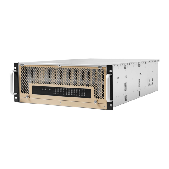
1.3 General Information Designed for high scalability and high availability in storage applications, the IW-RJ460-08 JBOD enclosure is a high density 4U rackmount storage chassis with 60 tool-less bays, dual hot-swap SAS 12Gbps expander modules, five Mini-SAS HD (SFF-8644) for each 12Gbps expander module, high- speed cooling fans for excellent thermal performance, dual redundant 1200W power modules, and GUI supports via Ethernet board. -
Page 7: Front Panel Controls And Indicators
1.3.1 Front Panel Controls and Indicators The front panel includes control buttons and LED indicators Name Color Status Description Blue Solid on System is powered on Power On/Off Button with LED System is off Press the button to activate chassis Chassis ID Button with LED Green Solid on... -
Page 8: Rear Panel Configuration
1.3.2 Rear Panel Configuration Item Item Fan Module 1 Primary Bridge Expander Module Fan Module 2 Secondary Bridge Expander Module Fan Module 3 CRPS Power Module 1 Fan Module 4 CRPS Power Module 2 PSU Status LED: Power Standby Power On Loss of Power... - Page 9 1.3.2.1 Expander (Bridge) Configuration Name Description Expander Module Handle SAS Port LEDs Host HBA/RAID card connection SAS Host Ports External uplink, connect to HBA/RAID card SAS Expansion Ports External downlink, connect to cascading JBOD Expander Module Status LED Heartbeat ID LED/Button Press the button to activate chassis identification Network Management Port Connect to ethernet remote monitoring...
-
Page 10: Hardware Installation
Power Supply Installation The IW-RJ460-08 has a built-in redundant power supply unit. With this function, the system is capable of operating if one of the modules fail. To replace it, users only need to release/remove the failed module, and then insert a functional module. - Page 11 2.5.1 Type of Rail Kit Please follow the instructions to install the rails on the cabinet or chassis rack according to the rail type you ordered. 2.5.2 Slide Rail 2.5.2.1 Take out the Inner Rail and Slide the Intermediate Rail Back Step 1: Pull out the inner rail until it reaches the stop.
- Page 12 2.5.2.3 Mounting the Rail Bracket to the Cabinet Step 1: Extend the rail bracket over the rear rack of the cabinet. Step 2: Pull out the rear hook on the end of the outer rail, align and push the rail bracket pins into the post holes on the rack.
- Page 13 2.5.2.4 Insert the Chassis to the Cabinet Step 1: Pull out the middle rail to the stop position. Step 2: Move the ball bearing retainer to the front end of the middle rail, it should click into the locked position. Step 3: Insert the inner rails of the chassis into the middle rails on both sides of the rack.
-
Page 14: Expander Board Introduction (Host & Disk)
Expander Board Introduction (Host & Disk) 3.1 Expander Board (Host) Name Description External Uplink CN1~CN4 (Host Facing Interface Mini-SAS HD Connector) External Downlink (Expansion Facing Interface Mini-SAS HD Connector) PD1~PD5 PHY LINK Activity LED Status/System Error LED ID Button & ID LED Management LAN Port Ethernet JTAG Header FAN1... - Page 15 3.2 Expander Board (Disk) Name Description External Uplink CN1~CN2 (Host Facing Interface Mini-SAS HD Connector) External Downlink (Expansion Facing Interface Mini-SAS HD Connector) EXP Debug Console Mode Connector EXP Smart Console Mode Connector FAN1 Expander Fan Connector Status/System Error LED DB1~DB3 PHY LINK Activity LED...
-
Page 16: Compatibility Lists
InWin’s chassis. You can download the latest updated device compatibility list ipc.in-win.com from InWin’s website: Technical Support If you need help with installation or troubleshooting, you can contact your local InWin reps, or send an e-mail to InWin’s local contacts for technical assistance. - Page 17 Co py r ig ht © I n W in D eve lo p m ent I n c . A l l Ri g ht s Res e r ved .
Need help?
Do you have a question about the IW-RJ460-08 and is the answer not in the manual?
Questions and answers