Table of Contents
Advertisement
Quick Links
CentronicPLUS
VC520 PLUS
Assembly and Operating Instructions
en
Flush-mounted potential-free radio receiver
Important information for:
• Fitters / • Electricians / • Users
Please forward accordingly!
These instructions must be kept safe for future reference.
4036 630 138 0b 02/09/2022
Becker-Antriebe GmbH
Friedrich-Ebert-Straße 2-4
35764 Sinn/Germany
www.becker-antriebe.com
Advertisement
Table of Contents

Subscribe to Our Youtube Channel
Related Manuals for Becker CentronicPLUS VC520 PLUS


Summary of Contents for Becker CentronicPLUS VC520 PLUS
- Page 1 Assembly and Operating Instructions Flush-mounted potential-free radio receiver Important information for: • Fitters / • Electricians / • Users Please forward accordingly! These instructions must be kept safe for future reference. 4036 630 138 0b 02/09/2022 Becker-Antriebe GmbH Friedrich-Ebert-Straße 2-4 35764 Sinn/Germany www.becker-antriebe.com...
-
Page 2: Table Of Contents
Table of contents General .................... 4 Licensing information for open source software.......... 5 Warranty .................... 5 Safety instructions ................... 6 Intended use ................... 7 Explanation of displays and buttons ............ 8 Explanation of functions ................ 9 Wiring .................... 10 Compatible Centronic transmitters ............ 12 Switching between operating modes ............ 13 Resetting the operating mode .............. 14 Commissioning with a CentronicPLUS transmitter ........ 15... - Page 3 Activating / deactivating the run times with a CentronicPLUS transmitter ....................... 44 Activating / deactivating the run times with a Centronic transmitter .. 44 Restoring the factory settings for the radio programming..... 45 Disposal .................... 45 Technical data .................. 46 What to do if...?.................. 47 Simplified EU declaration of conformity............. 48 3 - en...
-
Page 4: General
General The radio receiver, delivered ex works, converts radio signals into control sig- nals. A wired drive can be radio-controlled using the radio receiver. The radio receiver can be controlled with all transmitters in the CentronicPlus range of control units and with various transmitters in the Centronic range of control units (see Compatible Centronic transmitters [} 12]). -
Page 5: Licensing Information For Open Source Software
Written request for the licence texts: Becker-Antriebe will, on request, provide the licence texts for the licensed software being used at cost price, either on a USB stick or a similar data car- rier. Please send an email to the following email address for more information: licenses@becker‑antriebe.com... -
Page 6: Safety Instructions
Safety instructions The following safety instructions and warnings are intended to avert hazards and to prevent property damage and personal injury. General information • Always comply with regulations of local energy supply companies as well as VDE 100 provisions for wet and damp rooms during installation. •... -
Page 7: Intended Use
Intended use The radio receiver described by the present instructions must only be used for the operation of roller shutter, awning, blind and lighting control units. • Please note that radio-controlled systems may not be used in areas with a high risk of interference (e.g. hospitals, airports). •... -
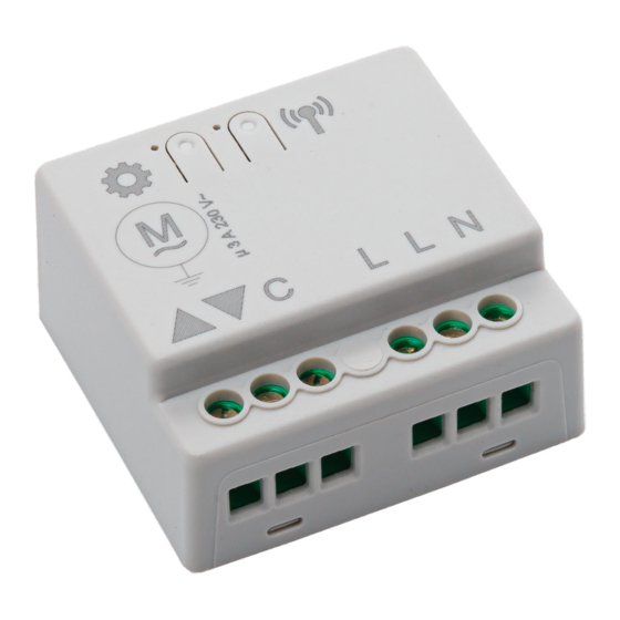
Page 8: Explanation Of Displays And Buttons
Explanation of displays and buttons L L N 1 Programming button 2 Connecting terminals 3 Mode button Roller shutter (factory setting) Sun protection Venetian blind Switching actuator Pulse Pulse 8 - en... -
Page 9: Explanation Of Functions
Explanation of functions Outputs Connect the drive to the outputs of the device. The arrows on the device show the direction in which the drive turns. Roller shutter operation By pressing a travel button, the roller shutter moves to the set limit position. Awning operation By pressing a travel button, the awning moves to the set limit position. -
Page 10: Wiring
Wiring Caution • Risk of injury due to electric shock. • Connection may only be performed by a qualified electri- cian! • The device only offers back-of-hand protection, not touch protection. • If two or more drives are going to be operated via the ra- dio receiver, the drives must be decoupled by relay con- trols. - Page 11 3. Set the operating mode as described in the chapter Switching between op- erating modes [} 13] 4. Programme a transmitter into the receiver. Sample wiring diagram with a 24 V DC tubular drive 1. Connect the device as follows: L L N 24 V BU (1) BN (2) BK (3) RD (4)
-
Page 12: Compatible Centronic Transmitters
All CentronicPlus receivers can be operated with the Centronic transmitters listed in the Centronic/CentronicPlus compatibility table at www.becker-antriebe.com/downloads As two fundamentally different radio technologies are linked in this case, the full performance of the CentronicPlus radio control system is not available in this combination. -
Page 13: Switching Between Operating Modes
Switching between operating modes The running time, tilt, intermediate positions, direction of ro- tation, programmed transmitter and installation data are de- leted when changing operating mode. Briefly pressing the mode button on the radio re- ceiver causes the adjacent LED to flash orange to indicate the current operating mode. -
Page 14: Resetting The Operating Mode
Resetting the operating mode The running time, tilt, intermediate positions, direction of ro- tation, programmed transmitter and installation data are de- leted when resetting the operating mode. Press the mode button until the adjacent LED starts to flash red and then lights up green. Re- lease the button as soon as the LED lights up green. -
Page 15: Commissioning With A Centronicplus Transmitter
Commissioning with a CentronicPLUS transmitter Explanation of symbols Explanation of symbols Up/retract button STOP button Down/extend button Programming button (on the transmitter) Programming button (on the radio receiver) Mode button (on the radio receiver) LED ring on the transmitter (only when using a CentronicPlus transmitter. -
Page 16: Programming The Centronicplus Transmitter
Programming the CentronicPLUS transmitter Caution • Risk of injury due to electric shock. • Connection may only be performed by a qualified electri- cian! • The device only offers back-of-hand protection, not touch protection. Establish programming mode Make sure that the required operating mode is selected. Putting the radio receiver into programming mode by switching on the power Switch on the power. - Page 17 With brand new products, devices from another installation or products that have been restored to factory settings, pro- gramming mode must be established beforehand (see Estab- lishing programming mode). Bring the transmitter as close as possible to the receiver to be programmed. Press the programming button for 3 seconds when it is ready to program.
- Page 18 Select the desired channel by pressing the func- tion key on the multi-channel hand-held transmit- ter. Press the STOP button to change the assignment status of the selected receiver. If the receiver is not yet part of the installation, it will be added and assigned to the selected channel.
-
Page 19: Selection Of The Receiver For The Setting Mode
Selection of the receiver for the setting mode Bring the transmitter as close as possible to the required receiver. Press the programming button for 3 seconds. The transmitter performs a search and the LED ring continuously changes colour. The transmitter then switches to receiver selection and selects the re- ceiver with the best connection quality. - Page 20 Briefly press the programming button to change to the setting mode. ▻ The receiver confirms. ▻ The LED ring of the transmitter slowly pulses light blue. ▻ The receiver now enters dead-man mode. ► The setting mode is now active. If a receiver has not yet been added to the installation (LED ring lights up yellow), it will not be possible to select it in this way.
-
Page 21: Changing Direction Of Rotation Via The Transmitter
Changing direction of rotation via the transmitter The direction of rotation can only be changed if no travel path has been set. The travel path will need to be deleted first if applicable, see chapter Deleting the travel path [} 24]. Changing the direction of rotation with a CentronicPLUS transmitter Select the required receiver as described in the... -
Page 22: Adding Additional Transmitters To The Installation
Adding additional transmitters to the installation If installation data already exists for the transmitter being programmed, the procedure will be terminated. Termination is indicated by the red flashing of the LED ring. In this case, the transmitter will need to be restored to factory settings (see corresponding transmitter instructions). -
Page 23: Setting The Travel Path
Setting the travel path Intermediate positions can only be fed back and pro- grammed once the travel path has been set. A time of between 1 second and 10 minutes can be set as the travel path. The set drive limit positions are not affected by changes to the programming of the travel path. -
Page 24: Deleting The Travel Path
If a travel path is set, the drive command will not be immedi- ately ended when the respective limit position is reached. The corresponding relay remains switched on for an addi- tional 60 seconds in order to ensure that the actual limit pos- ition is reached. -
Page 25: Intermediate Positions I + Ii
Intermediate positions I + II The intermediate positions I + II are freely selectable posi- tions for the shading solution between the two limit posi- tions. Each travel button can be assigned one intermediate position. The travel path must be set before an intermediate position is set. - Page 26 Travelling to the desired intermediate position Press the travel button for the desired intermedi- ate position twice within one second. ▻ The transmitter confirms with a rota- tional movement of the LED ring from blue to turquoise. ► The shading solution travels to the interme- diate position assigned to the travel button.
-
Page 27: Setting/Adjusting The Maximum Tilt (Venetian Blind Operation)
Deleting the intermediate positions Press the STOP button twice within 1 second and then press and hold for 5 seconds. ▻ The receiver confirms. ▻ The transmitter confirms with red pulsing of the LED ring. ► The intermediate positions have now been deleted. -
Page 28: Manually Adjusting The Slat Position
Manually adjusting the slat position Settings can only be adjusted using a SWCxxx PLUS hand- held transmitter. The receiver must be in blind mode. Make sure that the maximum tilt is already set; see chapter Setting/adjusting the maximum tilt (venetian blind operation) [} 27]. - Page 29 Select the required receiver as described in Se- lection of the receiver for the setting mode [} 19]. First press the programming button and, within 1 second, press the button at the same time and hold both buttons down for 3 seconds. ▻...
-
Page 30: Commissioning With A Centronic Transmitter
Commissioning with a Centronic transmitter Explanation of symbols Explanation of symbols Up/retract button STOP button Down/extend button Programming button (on the transmitter) Programming button (on the radio receiver) Mode button (on the radio receiver) Receiver confirms once or multiple times by switching outputs or by the mode LED illumin- ating Programming the Centronic transmitter... - Page 31 Putting the radio receiver into programming mode Putting the radio receiver into programming mode by switching on the power Switch on the power. ▻ The LED next to the programming but- ton flashes green. ► The radio receiver remains in programming mode for 3 minutes.
- Page 32 Press the programming button of the transmitter for 3 seconds whilst in programming mode. ▻ The receiver confirms. ► Programming is now complete. Programming additional transmitters In addition to the master transmitter, up to 15 further trans- mitters (of which a maximum of three can be sensors) can be programmed in the radio receiver.
-
Page 33: Changing Direction Of Rotation Via Master Transmitter
Changing direction of rotation via master transmitter The direction of rotation can only be changed if no travel path has been set. The travel path will need to be deleted first if applicable, see chapter Deleting the travel path with a Centronic transmitter [} 38]. -
Page 34: Deleting Transmitters
Deleting transmitters Deleting individual transmitters The programmed master transmitter cannot be deleted. It can only be overwritten (see Programming the Centronic trans- mitter [} 31]). Press the programming button on the master transmitter for 3 seconds. ▻ The receiver confirms. Now press the programming button of the trans- mitter to be deleted for 3 seconds. -
Page 35: Overwriting The Master Transmitter
Deleting all transmitters (except the master transmitter) Press the programming button on the master transmitter for 3 seconds. ▻ The receiver confirms. Re-press the programming button on the master transmitter for 3 seconds. ▻ The receiver confirms. Re-press the programming button on the master transmitter for 10 seconds. - Page 36 Switch off the power supply to the radio receiver. Switch the power supply to the radio receiver back on after 10 seconds. ▻ The receiver confirms. ▻ The receiver goes into the program- ming mode for 3 minutes. Now press the programming button of the new master transmitter for 10 seconds.
-
Page 37: Setting The Travel Path With A Centronic Transmitter
Setting the travel path with a Centronic transmitter Intermediate positions can only be fed back and pro- grammed once the travel path has been set. A time of between 1 second and 10 minutes can be set as the travel path. -
Page 38: Deleting The Travel Path With A Centronic Transmitter
Deleting the travel path with a Centronic transmitter When the travel path is deleted, the set intermediate posi- tions will be deleted as well. Open/close the shading solution to a point between the limit positions. First press the programming button and, within 1 second, press the STOP button at the same time and hold both buttons down for 10 seconds. - Page 39 Travelling to the desired intermediate position Press the travel button for the desired intermedi- ate position twice within one second. ► The shading solution travels to the interme- diate position assigned to the travel button. Deleting the desired intermediate position Move the shading solution to the intermediate po- sition that is to be deleted.
-
Page 40: Setting/Adjusting The Maximum Tilt (Venetian Blind Operation)
Setting/adjusting the maximum tilt (venetian blind operation) Set the travel path as described in the chapter Setting the travel path with a Centronic transmitter [} 37]. Move the blind to the lower limit position. Then move out of the closed position (in setting mode) in the direction until the slats of the venetian blind are completely open. - Page 41 Setting a running time (optional) In this operating mode, a running time can be programmed in the device. The radio receiver switches off automatically once the set time has elapsed. The time can be adjusted up to max. 10 minutes. First press the programming button and, within 1 second, press the button at the same time and...
-
Page 42: Additional Functions With Centronicplus / Centronic
Programming the run times This function is available with all CentronicPlus EasyControl transmitters and with Centronic devices only equipped with "MemoControl" transmitters from the Becker range of con- trol units. Both limit positions must be set before the Memo function is set. -
Page 43: Deleting The Run Times With A Centronicplus Transmitter
Deleting the run times with a CentronicPLUS transmitter When deleting, both run times are always deleted. Press the STOP button for 10 seconds. ▻ The receiver confirms. ▻ The transmitter confirms with red pulsing of the LED ring. ► The run times are now deleted. Deleting the run times with a Centronic transmitter When deleting, both run times are always deleted. -
Page 44: Activating / Deactivating The Run Times With A Centronicplus Transmitter
Activating / deactivating the run times with a Centronic transmitter This function is only available with MemoControl transmitters from the Becker Centronic range of control units. The Memo function is activated and deactivated via the slide switch. The last changeover to be performed is valid. -
Page 45: Restoring The Factory Settings For The Radio Programming
Restoring the factory settings for the radio programming When resetting the radio programming, all programmed transmitters and installation data for CentronicPLUS, Centronic and the sensors will be deleted. Settings required for the particular operating mode will remain in place. Press the programming button until the adjacent LED starts to flash red and then lights up green. -
Page 46: Technical Data
Technical data Rated voltage 110-240 V AC/50-60 Hz Switching current AC µ 3A/110-240 V AC Switching current DC µ 3A/30 V DC Degree of protection IP 20 Class of protection (dependent on correct assembly) Permissible ambient temperature -25 to +50°C Roller shutter/awning running time 1 s to 10 min. -
Page 47: What To Do If
What to do if...? Problem Remedy Tubular drive/receiver is not re- Insert a new battery/batteries into sponding. the hand-held transmitter. Make sure the battery/batteries is/ are correctly inserted in the hand- held transmitter. Reduce distance from receiver. Program transmitter. Check connection. The LED ring on the hand-held trans- Reduce distance from receiver. -
Page 48: Simplified Eu Declaration Of Conformity
Simplified EU declaration of conformity Becker-Antriebe GmbH hereby declares that this radio control system com- plies with Directive 2014/53/EU. The full text of the EU declaration of conformity is available at the following web address: www.becker-antriebe.com/ce...
Need help?
Do you have a question about the CentronicPLUS VC520 PLUS and is the answer not in the manual?
Questions and answers