Table of Contents
Advertisement
Quick Links
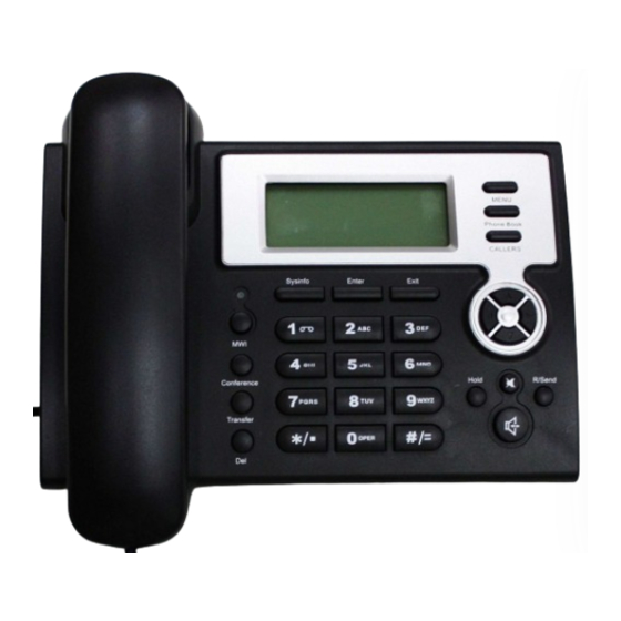
EP210 VoIP Phone
User Manual
Version: V1.7.60.47 Mar 30 2009
© 2005 Datang Gohigh Network technology Co,. Ltd
All rights reserved.
This document is supplied by Gohigh Technology Co., Ltd, No part of
this document may be reproduced, republished or retransmitted in
any form or by any means whatsoever, whether electronically or
mechanically, including, but not limited to, by way of photocopying,
recording, information recording or through retrieval systems,
without the express written permission of Gohigh Technology Co.,
Ltd. Gohigh Technology Co., Ltd reserves the right to revise this
document and make changes at any time and without the
obligation to notify any person and/or entity of such revisions
and/or changes. Product specifications contained in this document
are subject to change without notice.
Advertisement
Table of Contents

Subscribe to Our Youtube Channel
Related Manuals for GoHigh EP210

Summary of Contents for GoHigh EP210
- Page 1 © 2005 Datang Gohigh Network technology Co,. Ltd All rights reserved. This document is supplied by Gohigh Technology Co., Ltd, No part of this document may be reproduced, republished or retransmitted in any form or by any means whatsoever, whether electronically or...
- Page 2 Safety Notices Please read the following safety notices before installing or using this phone. They are crucial for the safe and reliable operation of the device. Please use the external power supply that is included in the package. Other power supplies may cause damage to the phone, affect the behavior or induce noise.
-
Page 3: Table Of Contents
Table of Content INTRODUCING EP210 VOIP PHONE ....................5 1.1. T EP210 ..................5 HANK YOU FOR YOUR PURCHASING 1.2. D .......................... 5 ELIVERY ONTENT 1.3. K ............................5 EYPAD 1.4. P ........................6 ORT FOR CONNECTING 2.INITIAL CONNECTING AND SETTING ....................7 2.1. - Page 4 4.3.5.5. Account Config ......................38 4.3.5.6. Reboot ..........................39 4.3.6. Security ..........................40 4.3.6.1. MMI Filter ..............................4.3.6.2. Firewall ..............................4.3.7. Logout ........................... 42 4.4. S ’ ....................42 ETTINGS VIA PHONE S KEYBOARD 4.4.1. How to set via the phone’s keyboard................42 4.4.2.
-
Page 5: Introducing Ep210 Voip Phone
1.1. Thank you for your purchasing EP210 Thank you for your purchasing EP210, EP210 is a full-feature telephone that provides voice communication over the same data network that your computer uses. This phone functions not only much like a traditional phone, allowing to place and receive calls, and enjoy other features that traditional phone has, but also it own many data services features which you could not expect from a traditional telephone. -
Page 6: Port For Connecting
Callers In idle/pickup/calling mode, press the Callers key to Check the Income/Outgoing/Missed calls records. Press this key again will return to idle mode LED blinks to remind user new voicemail. System In idle mode, press the Sysinfo key to check the phone Information setting parameters. -
Page 7: Initial Connecting And Setting
POWER Power switch Select ON/OFF Power port Output: 5V/1.0A Network port Connect it to PC Network port Connect it to Network The phone has two Network ports: The WAN port and the LAN port. Before you connect the power source, please carefully read Safety Notices of this user manual. -
Page 8: Initial Setting
Shared network connection—Use this method if you have a single Ethernet port in your workspace with your desktop computer already connected to it. First, disconnect the Ethernet cable from the computer and attach it to the WAN port on the back of your phone. Next, use the Ethernet cable in the package to connect LAN port on the back of your phone to your desktop computer. -
Page 9: Static Ip Mode
will switch into PPPoE mode. Prepare your PPPoE account name and password. 2. Press the MENU key, the LCD screen will display “INPUT PASSWORD”. 3. Input the password (default value is 123), and press the ENTER key, the LCD screen will display “NETWORK”. -
Page 10: Dhcp Mode
5. Press the key, the LCD screen will display “IP”. Press the key again and then the key, input your desired IP address for your IP phone and confirmed by pressing the key, then the LCD will display the inputted IP address. When inputting IP with keypad, use “*” instead of “.”. 6. -
Page 11: Basic Functions
Press the numeric key 2 and hold till the LCD screen displays “ARE YOU SURE”. Press the key, the LCD screen will display “CHANGING” and this VoIP phone is trying to switch to DHCP mode. If the icom “DHCP” on the top of the screen keeps blink, it shows that the phone is trying to access the DHCP server., and the IP is 0.0.0.0 if you press key to display the current IP;... -
Page 12: Ending A Call
Pick up the handset, and the LCD screen will display “PLEASE DIAL” and you will hear dialing tone at the same time, then input the phone number and end by the # button. When you hear long ring “du, du…” from handset and the LCD screen display “CALLING”, the call is through. -
Page 13: Calling Hold And 3 Ways Call
presses the key, A will get through to C. 3. When A talks to B, B presses the key, dial C phone number and # key, then hang up and A will get through to C. 1 and 2 are attended transfer; 3 is blind transfer. Notice to VoIP Phone Carrier: Your VoIP phone server need support FRC3515, or else transferring can not work. -
Page 14: The High-Level Operation
You can press the key to dial this phone number, you also press key to browse the other received calls or you can press the key again, the LCD screen will show the time of the received call. If there is no one received call, the LCD will display “LIST IS EMPTY”. Dialed calls Press the key, and then the... -
Page 15: Redial/Unredial
*2* means appointed prefix code. After making the above configuration, A can dial *2* plus B or C number to join B and C’s call, . User can set prefix in random, in the case of no affecting current dialing rules. -
Page 16: Configuration Via Web
When this phone and your PC are connected to your network, enter the IP address of the wan port in this phone as the URL (e.g. http://xxx.xxx.xxx.xxx/ or http://xxx.xxx.xxx.xxx:xxxx/). If you do not know the IP address, you can look it up on the phone’s display by pressing the key “SYSINFO”. -
Page 17: Wizard
Status Field name Explanation Shows the configuration information on WAN and LAN port, Network including the connect mode of WAN port (Static, DHCP, PPPoE), MAC address, the IP address of WAN port and LAN port, ON or OFF of DHCP mode of LAN port. Phone Number Shows the phone numbers provided by the SIP LINE 1-2 servers. - Page 18 Static IP Address Input the IP address distributed to you. Netmask Input the Netmask distributed to you. Gateway Input the Gateway address distributed to you. DNS Domain Set DNS domain postfix. When the domain which you inputted can not be parsed, phone will automatically add this domain to the end of the domain which you inputted before and parse it again.
-
Page 19: Call Log
Username Input your ADSL account. Password Input your ADSL password. Notice: Click【 【 【 【 Finish】 】 】 】 button after finish your setting, IP Phone will save the setting automatically and reboot. After reboot, you can dial by the SIP account. 4.3.1.3. - Page 20 WAN Config Field Name explanation Active IP The current IP address of the phone. Current Netmask The current Netmask address. MAC Address The current MAC address of the phone. Current Gateway The current Gateway IP address. Get MAC Time Shows the time of getting MAC address Please select the proper network mode according to the network condition.
-
Page 21: Qos Config
of the domain which you inputted before and parse it again. Primary DNS Input your primary DNS server address. Alter DNS Input your standby DNS server address. If you uses PPPoE mode, you need to make the above setting. PPPoE Server It will be provided by ISP. - Page 22 In chart 1, there is a layer 2 switch without setting VLAN. Any broadcast frame will be transmitted to the other ports except the send port. For example, a broadcast information is sent out from port 1 then transmitted to port 2,3and 4. In chart 2, red and blue indicate two different VLANs in the switch, and port 1 and port 2 belong to red VLAN, port 3 and port 4 belong to blue VLAN.
-
Page 23: Service Port
differentiated packets will add voice VLAN ID, and other data packets will add data VLAN ID; data untaged means after using VLAN, only VoIP packets will add voice VLAN ID. Other data packets will not use VLAN. DiffServ Enable Select it or not to Enable or disable DiffServ. DiffServ Value Set DiffServ value, the common value is 0x00. -
Page 24: Sntp
Telnet Port Set Telnet Port, the default is 23. You can change the value into others. Example: The IP address is 192.168.1.70. the telnet port value is 8023, the accessing address is telnet 192.168.1.70 8023 RTP Initial Port Set the RTP Initial Port. It is dynamic allocation. RTP Port Quantity Set the maximum quantity of RTP Port, the default is 200. -
Page 25: Voip
Hour Setup start and end hours Minute Setup start and end minutes Notice: You need specify the above all items. 4.3.3. VOIP 4.3.3.1. SIP Config Set your SIP server in the following interface. - Page 26 SIP Config Field name explanation You can switch by 【 【 【 【 Load】 】 】 】 Choose line to set info about SIP, there are 2 lines to choose. button. Register Status Shows if the phone has been registered the SIP server or not; or so, show Unapplied;...
-
Page 27: Stun Config
server Enable URI Convert Convert # to %23 when send the URI. Dial Without Register Set call out by proxy without registration; Ban Anonymous Call Set to ban Anonymous Call; Select call forward mode, the default is Off Off:Close down calling forward Forward Type Busy:If the phone is busy, incoming calls will be forwarded to the appointed phone. - Page 28 STUN Field name explanation STUN NAT Transverse Shows STUN NAT Transverse estimation, true means STUN can penetrate NAT, while False means not. STUN Server Addr Set your SIP STUN Server IP address STUN Server Port Set your SIP STUN Server Port Set STUN Effective Time.
-
Page 29: Dial Peer Setting
4.3.3.3. DIAL PEER setting This functionality offers you more flexible dial rule, you can refer to the following content to know how to use this dial rule. When you want to dial an IP address, the entry of IP addresses is very cumbersome, but by this functionality, you can set number 156 to replace 192.168.1.119 here. - Page 30 There are two types of matching conditions: one is full matching, the other is prefix matching. In the Full matching, you need input your desired phone number in this blank, and then you need dial the Phone number phone number to realize calling to what the phone number is mapped.
- Page 31 You need set phone number, If you dial “93333”, Destination, Alias and Delete the SIP2 server will Length. receive “3333” Phone number XXXT, Destination is 255.255.255.255 and Alias is del. This means any phone No. that starts with your set phone number will be sent via SIP2 line after the first several digits of your dialed phone number are...
-
Page 32: Phone
4.3.4. Phone 4.3.4.1. DSP Config In this page, you can configure voice codec, input/output volume and so on. DSP Configuration Field name explanation First Codec The fist preferential DSP codec: G.711A/u, G.722, G.723, G.729, G.726 Second Codec The second preferential DSP codec: G.711A/u, G.722, G.723, G.729,G.726 Third Codec The third preferential DSP codec: G.711A/u, G.722, G.723,... - Page 33 Call Service Field name explanation Hotline Specify Hotline number. If you set the number, you can not dial any other numbers. No Answer Time Specify No Answer Time Set Prefix in peer to peer IP call. For example: what you want to dial is P2P IP Prefix 192.168.1.119, If you define P2P IP Prefix as 192.168.1., you dial only #119 to reach 192.168.1.119.
-
Page 34: Digital Map Configuration
may add the number(s) to the list as the white list rule. the configuration rule is -number, for example, -123456, or -1234xx Means any incoming number is forbidden except for 4119 Note: End with DOT (.) when set up the white list Set Add/Delete Limit List. -
Page 35: Phone Book
Set the timeout of the last dial digit. The call will be sent after Time out timeout. Below is user-defined digital map rule: [] Specifies a range that will match digit. May be a range, a list of ranges separated by commas, or a list of digits. -
Page 36: Maintenance
Number Shows the phone number Ring Type Shows the ring type of the incoming call. Click “Modify” to change the selected information and click the “Delete” to delete the selected record. Notice: the maximum capability of the phonebook is 500 items 4.3.5. -
Page 37: Config Setting
Level 5---notice: Your system works well in special condition, but you need to check its working environment and parameter. Level 6---info: the daily debugging info. Level 7---debug: the lowest debug info. Professional debugging info from R&D person. At present, the lowest level of debug information send to Syslog is info, debug level only can be displayed on telnet. -
Page 38: Update
If you login as Admin, the phone will reset all configurations and Clear Config restore factory default; if you login as Guest, the phone will reset all configurations except for VoIP accounts (SIP1-2 and IAX2) and version number. 4.3.5.4. Update You can update your configuration with your config file in this web page. -
Page 39: Reboot
Account Configuration Field name explanation Keyboard Password Set the password for entering the setting menu of the phone by the phone ‘s key board. The password is digit. This table shows the current user existed. User Name Set account user name. User Level Set user level, Root user has the right to modify configuration, General can only read. -
Page 40: Security
4.3.6. Security 4.3.6.1. MMI Filter MMI Filter User could make some device own IP, which is pre-specified, access to the MMI of the phone to config and manage the phone. Field name explanation MMI Fileter IP Table list: Add or delete the IP address segments that access to the phone. Set initial IP address in the Start IP column, Set end IP address in the End IP column, and click Add to add this IP segment. - Page 41 Firewall Configuration In this web interface, you can set up firewall to prevent unauthorized Internet users from accessing private networks connected to the Internet (input rule), or prevent unauthorized private network devices from accessing the Internet (output rule). Firewall supports two types of rules: input_access rule and output_access rule. Each type supports at most 10 items.
-
Page 42: Logout
source address’ mask. For example, 255.255.255.255 means Set the Src Mask just point to one host; 255.255.255.0 means point to a network which network ID is C type. destination address’ mask. For example, 255.255.255.255 Set the Des Mask means just point to one host; 255.255.255.0 means point to a network which network ID is C type. -
Page 43: Appendix
5. Appendix 5.1. Specification 5.1.1. Device specification Item this VoIP Phone Adapter(Input/Output) Input:100-240VAC 50~60Hz Output:5V/1A 10/100Base- T RJ-45 for LAN, Auto MDIX Port 10/100Base- T RJ-45 for PC, Auto MDIX Power Consumption Idle:1.5W/Active:1.8W LCD size 74 x 28mm Operation Temperature 0~40℃... -
Page 44: Network Features
Echo cancellation: Support G.168 and hand-free can support 96ms Support VAD,CNG NAT transverse: support STUN Supports full duplex. SIP support SIP domain, SIP authentication (none, basic, MD5) , DNS name of server, peer to peer SIP support 2 servers, user can through each server to calling in and out DTMF:SIP info,DTMF Relay,RFC2833 SIP application: contain SIP call forward/transfer/holding/waiting/3 way conference/Paging and intercom/ click to dial/pickup/ joincall/redial/unredial. - Page 45 5 J K L j k l 6 M N O m n o...
Need help?
Do you have a question about the EP210 and is the answer not in the manual?
Questions and answers