Table of Contents
Advertisement
Quick Links
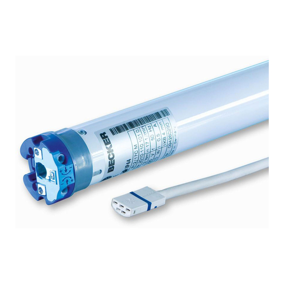
R7/17
Version: M
Assembly and Operating Instructions
en
Roller shutter and sun protection drives with
mechanical limit switch
Important information for:
• Fitters / • Electricians / • Users
Please forward accordingly!
These instructions must be kept safe for future reference.
2010 300 597 0a 24/08/2022
Becker-Antriebe GmbH
Friedrich-Ebert-Straße 2-4
35764 Sinn/Germany
www.becker-antriebe.com
Advertisement
Table of Contents

Subscribe to Our Youtube Channel
Related Manuals for Becker R7/17


Summary of Contents for Becker R7/17
- Page 1 R7/17 Version: M Assembly and Operating Instructions Roller shutter and sun protection drives with mechanical limit switch Important information for: • Fitters / • Electricians / • Users Please forward accordingly! These instructions must be kept safe for future reference.
-
Page 2: Table Of Contents
Table of contents General .................................... 3 Warranty ..................................... 3 Safety instructions ................................ 4 Instructions for the user.............................. 4 Instructions for installation and commissioning........................ 4 Intended use .................................. 6 Assembly .................................... 6 Setting the limit positions.............................. 9 Information for the electrician ............................. 10 Disposal .................................... -
Page 3: General
General These tubular drives are high-quality products with the following features: • For use with roller shutters • For use with sunblinds • Easy limit switch setting on the drive • Compatible with all of the drive manufacturer's control units for roller shutters and sunblinds. Please observe these Assembly and Operating Instructions when installing and setting the equipment. -
Page 4: Safety Instructions
Safety instructions The following safety instructions and warnings are intended to avert hazards and to prevent property damage and personal injury. Instructions for the user General information • The drive must be disconnected from its power source during cleaning and maintenance and when re- placing parts. - Page 5 • If the drive is used for shading solutions in a specially marked area (e.g., escape routes, hazard zones, safety areas), compliance with all applicable regulations and standards must be ensured. • Once the drive has been installed, the fitter must mark the used tubular drive in the “Technical data” chapter and make a note of the installation position.
-
Page 6: Intended Use
Intended use The type of tubular drive described in these instructions is intended solely for the operation of roller shutters and sun protection systems. This type of tubular drive is designed for use in single systems (one drive per barrel). The tubular drive must not be used in potentially explosive areas. - Page 7 Assembling and disassembling the drive adapter Fitting the ring onto the thrust ring Assembling the drive adapter with safety catch on the Disassembling the drive adapter with safety catch on the drive shaft drive shaft Assembling and disassembling the drive adapter with drive adapter safety catch or screw connection Assembling and disassembling the drive Assembling and disassembling the drive adapter with separate drive adapter...
- Page 8 Assemble the tubular drive with the relevant ring (1) and drive adapter (2). If the ring has several grooves, select the groove which is a perfect fit and push the ring (1) onto the thrust ring. Insert the tubular drive with the pre-assembled ring (1) and drive adapter (2) into the tube to achieve a form fit.
-
Page 9: Setting The Limit Positions
Setting the limit positions Upper limit position Lower limit position Lower limit position Upper limit position Setting the lower limit position 1. Before the shading solution is fixed to the barrel, let the drive run DOWN until it switches off automatically. 2. -
Page 10: Information For The Electrician
Information for the electrician The tubular drives with mechanical limit switching must not be connected in parallel. The drive manufacturer offers a range of suit- able controls for the simultaneous control of several drives. Use external conductor L1 to control the up and down direction. Other devices or consumers (lamps, relays, etc.) must not be dir- ectly connected to the drive connecting cables. -
Page 11: What To Do If
What to do if...? Problem Cause Remedy The roller shutter curtain is raised un- 1. One or more attachments have Repair system; then reset the limit posi- evenly or not at all. broken off. tions. 2. Lath has broken off. Tubular drive stops arbitrarily;... - Page 12 Central, group and individual control using Centronic UnitControl UC42 Central Control unit Mains 230 V / 50 Hz Central cable 230 V / 50 Hz (connection to further control units) Group 230 V / 50 Hz Individual Individual 230 V / 50 Hz 230 V / 50 Hz 12 - en...
-
Page 13: Declaration Of Conformity
Declaration of conformity 13 - en...
Need help?
Do you have a question about the R7/17 and is the answer not in the manual?
Questions and answers