Table of Contents
Advertisement
Quick Links
IQS227-228ASEV02 Evaluation Kit User Guide
1
Introduction .............................................................................................................................. 1
2
Standalone/Data Streaming EV-Kit .......................................................................................... 1
3
Standalone Operation .............................................................................................................. 2
3.1
Powering on the device .................................................................................................... 2
3.2
Device operation .............................................................................................................. 2
4
Data Streaming Operation ....................................................................................................... 3
4.1
Overview of module boards .............................................................................................. 3
4.2
Setup for data streaming on computer .............................................................................. 3
4.3
Using the GUI with the IQS227AS IC................................................................................ 4
4.4
Using the GUI with the IQS228AS IC................................................................................ 7
4.5
Configuring the IQS227AS and IQS228AS ....................................................................... 8
5
Communications Interface ....................................................................................................... 8
6
Reference Designs .................................................................................................................. 8
1 Introduction
This user guide describes the operation of the IQS227-228ASEV02 Evaluation Kit. The EV-Kit
consists of ten parts, the main board device, six separate plug-in module boards and three
overlays. Additional unprogrammed IC's (3 x IQS227AS and 3 x IQS228AS) are included. To
visualise raw data from the EV-Kit, the main board can be interfaced to any personal computer
with USB support, and IQS227 or IQS228 software GUI (Graphical User Interface). The purpose of
the IQS227-228ASEV02 EV-Kit is to help application and development engineers in evaluating the
IQS227AS and IQS228AS proximity and touch sensor in self-capacitance mode.
2 Standalone/Data Streaming EV-Kit
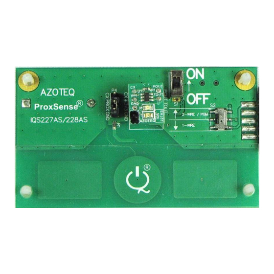
Figure 2.1 illustrates the evaluation kit main board and a plug-in module board.
Main board
Figure 2.1 IQS227AS/228AS main board with plugged in IQS227AS module board
Copyright © Azoteq (Pty) Ltd 2013
All Rights Reserved
IQ Switch
ProxSense
®
IQ Switch
- ProxSense
Table of Contents
Module board
IQS227-228ASEV02 Evaluation Kit User Guide
Revision 1.0
®
®
Series
®
Series
Page 1 of 10
December 2013
Advertisement
Table of Contents

Subscribe to Our Youtube Channel
Related Manuals for Azoteq IQ Switch ProxSense IQS227-228ASEV02


Summary of Contents for Azoteq IQ Switch ProxSense IQS227-228ASEV02
-
Page 1: Table Of Contents
Figure 2.1 illustrates the evaluation kit main board and a plug-in module board. Module board Main board Figure 2.1 IQS227AS/228AS main board with plugged in IQS227AS module board Copyright © Azoteq (Pty) Ltd 2013 IQS227-228ASEV02 Evaluation Kit User Guide Page 1 of 10 All Rights Reserved Revision 1.0... -
Page 2: Standalone Operation
Reference designs for IQS227AS and IQS228AS with user proximity and touch detection. Used in Data Streaming Mode: EV-Kit requires Mini-USB cable with Azoteq CT2xx/DS1xx. The EV-Kit main board can also draw power from a USB source by means of the mini-USB connector provided on the main board (optional). -
Page 3: Data Streaming Operation
4 Data Streaming Operation The device can also be connected to a computer via the Azoteq CT2xx/DS1xx and the data streamed. The difference between the module boards will become clearly when visualised on a computer. A quick overview of the module boards will come next followed by the setup procedure for a computer and the GUI. -
Page 4: Using The Gui With The Iqs227As Ic
In the Message box, “Compatible device(s) detected” should be displayed. If the message “No compatible device(s) connected!” is displayed, there is a connection problem between the Copyright © Azoteq (Pty) Ltd 2013 IQS227-228ASEV02 Evaluation Kit User Guide Page 4 of 10 All Rights Reserved Revision 1.0... - Page 5 Every time the Counts value rise to outside a certain level above the LTA, the IC adjusts the Compensation for the Counts to be as close as possible to the Target value. Copyright © Azoteq (Pty) Ltd 2013 IQS227-228ASEV02 Evaluation Kit User Guide...
- Page 6 Touch event should look like. Note that the Counts and LTA bars have turned red to indicate a Touch event and the Filter Halt is still Active. Copyright © Azoteq (Pty) Ltd 2013 IQS227-228ASEV02 Evaluation Kit User Guide...
-
Page 7: Using The Gui With The Iqs228As Ic
Touch mode, the Filter Halt is deactivated and the LTA now follow the Counts. This is needed as during long Touch events the environment can change and the device Copyright © Azoteq (Pty) Ltd 2013 IQS227-228ASEV02 Evaluation Kit User Guide... -
Page 8: Configuring The Iqs227As And Iqs228As
Black module boards to observe the different sensitivity levels obtainable. 4.5 Configuring the IQS227AS and IQS228AS Use the USBProg program, available from the Azoteq website, to burn fuses on the IQS227AS IC or IQS228AS IC. Consult the IQS227AS and IQS228AS datasheets for more information available on the Azoteq website. - Page 9 ® IQ Switch ® ProxSense Series Figure 6.2 IQS227-228ASEV02 Module board design Copyright © Azoteq (Pty) Ltd 2013 IQS227-228ASEV02 Evaluation Kit User Guide Page 9 of 10 All Rights Reserved Revision 1.0 December 2013...
- Page 10 Azoteq makes no warranty or representation that such applications will be suitable without further modification, nor recommends the use of its products for application that may present a risk to human life due to malfunction or otherwise. Azoteq products are not authorized for use as critical components in life support devices or systems. No licenses to patents are granted, implicitly, express or implied, by estoppel or otherwise, under any intellectual property rights.
Need help?
Do you have a question about the IQ Switch ProxSense IQS227-228ASEV02 and is the answer not in the manual?
Questions and answers