Table of Contents
Advertisement
Quick Links
Advertisement
Table of Contents

Subscribe to Our Youtube Channel
Summary of Contents for IFM KB
- Page 1 Operating instructions Capacitive sensor KB / KD /...
-
Page 2: Table Of Contents
KB / KD / KI Capacitive sensor Contents Preliminary note ............. -
Page 3: Preliminary Note
Capacitive sensor KB / KD / KI 1 Preliminary note You will find instructions, technical data, approvals, accessories and further information using the QR code on the unit / packaging or at www.ifm.com. 1.1 Symbols used Requirement Instructions Reaction, result [...] Designation of keys, buttons or indications... -
Page 4: Safety Instructions
KB / KD / KI Capacitive sensor 2 Safety instructions • The unit described is a subcomponent for integration into a system. – The system architect is responsible for the safety of the system. – The system architect undertakes to perform a risk assessment and to create documentation in accordance with legal and normative requirements to be provided to the operator and user of the system. -
Page 5: Intended Use
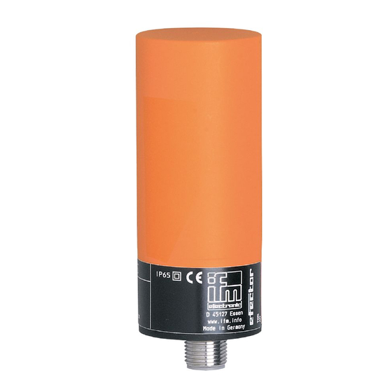
Capacitive sensor KB / KD / KI 3 Intended use The unit detects without contact metals, almost all plastics, glass, ceramics, wood, paper, oils, greases, water and all hydrous materials and indicates their presence by a switching signal. -
Page 6: Installation
KB / KD / KI Capacitive sensor 4 Installation For flush installation of non-flush units the sensor properties change and the sensor may remain permanently switched (loss of function). 4.1 Minimum distance for flush installation Sn: Sensing range Fig. 1: Minimum distance for flush installation 4.2 Minimum distance for non-flush installation... -
Page 7: Minimum Distance When Installing Type Kd
Capacitive sensor KB / KD / KI 4.4 Minimum distance when installing type KD Sn: Sensing range Fig. 4: Minimum distance for non-flush installation of type The distances need to be checked and determined by the users themselves according to their application. -
Page 8: Electrical Connection
KB / KD / KI Capacitive sensor 5 Electrical connection The unit must be connected by a qualified electrician. The national and international regulations for the installation of electrical equipment must be adhered to. u Disconnect power. u Connect the unit as specified in the data sheet / type label. -
Page 9: 2-Wire Technology
Capacitive sensor KB / KD / KI 5.3.1 2-wire technology Fig. 8: Terminal chamber AC/DC PNP/NPN Fig. 9: Terminal chamber DC PNP/NPN 5.3.2 3-wire technology Fig. 10: Terminal chamber DC NPN Fig. 11: Terminal chamber DC PNP Fig. 12: Connector DC PNP... -
Page 10: Settings
KB / KD / KI Capacitive sensor 6 Settings 6.1 Sensing range u Set the sensing range via the potentiometer using a screwdriver. 1: Increase the sensing range 2: Reduce the sensing range 6.2 Setting the output function via wire link for type KI with... -
Page 11: Operation
Capacitive sensor KB / KD / KI 7 Operation u Check whether the unit operates correctly. u Bring about a unit response by taking suitable measures. LED display LED yellow out: switching output disabled LED yellow ON: switching output enabled... -
Page 12: Maintenance, Repair And Disposal
KB / KD / KI Capacitive sensor 8 Maintenance, repair and disposal The operation of the unit is maintenance-free. To ensure correct functioning, please note the following: u Keep the sensing face and any clear spaces free from deposits and foreign bodies.


Need help?
Do you have a question about the KB and is the answer not in the manual?
Questions and answers