Advertisement
Quick Links
OWNER'S GUIDE & INSTALLATION INSTRUCTIONS
Transom-Mount
with Integrated Bracket
Speed
Models: S69, ST69
Patent http://www.airmar.com/patent.html
Follow the precautions below for optimal product
performance and to reduce the risk of property
damage, personal injury, and/or death.
WARNING: Always wear safety glasses, a dust mask,
and ear protection when installing.
WARNING: When the boat is placed in the water,
immediately check for leaks around the screws and
any other holes drilled in the hull.
CAUTION: Never pull, carry, or hold the sensor by the
cable as this may sever internal connections.
CAUTION: Never strike the sensor.
CAUTION: Never use solvents. Cleaners, fuel, paint,
sealants, and other products may contain solvents
that can damage plastic parts.
IMPORTANT: Please read the instructions completely
before proceeding with the installation. These
instructions supersede any other instructions in your
instrument manual if they differ.
Applications
• Not recommended for boats with large inboard engine(s).
• Good operation from 4 - 50kn (5 - 58MPH)
• Adjusts to transom angles from 3
Tools & Materials
Safety glasses
Dust mask
Ear protection
Angle finder
Screwdrivers
Weak solvent (alcohol)
Straight edge
Electric drill
Drill bits:
Mounting holes
Transom hole (optional)
Cable clamp holes
Masking tape
Marine sealant (suitable for below waterline)
Putty knife
Pencil
Grommet(s) (some installations)
Cable ties
Water-based antifouling paint (mandatory in salt water)
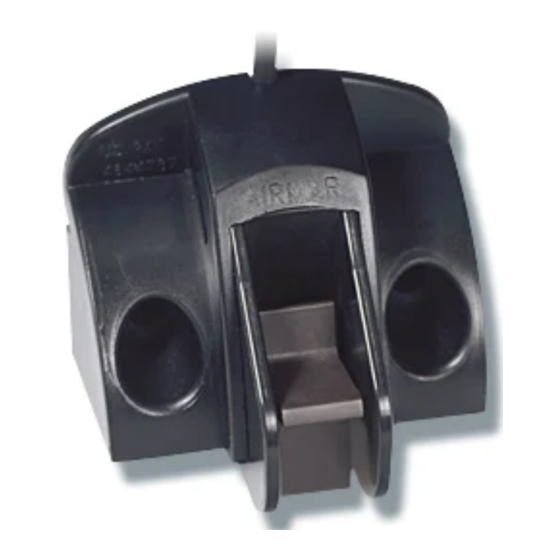
Temperature Sensor
&
- 16
5.4mm, #3, or 13/64"
20mm or 13/16"
3mm or 1/8"
Record the information found on the cable tag for future reference.
Part No._________________Date___________
Pretest
Connect the sensor to the instrument and spin the paddlewheel.
Check for a speed reading and the approximate air temperature. If
there is no reading(s) or it is inaccurate, check the connections
and repeat the test. If there is still no reading(s) or it is inaccurate,
return the product to your place of purchase.
Mounting Location
CAUTION: Do not mount the sensor in line with or near water
intake or discharge openings or behind strakes, fittings, or hull
irregularities that may disturb the water flow.
CAUTION: Do not mount the sensor in a location where the boat
may be supported during trailering, launching, hauling, or storage.
• For the best performance, the sensor must be in contact with
smooth water. To identify an area of clean water, observe the
water flow off the transom while the boat is underway.
• Mounting on the side of the transom where the propeller blades
are moving downward is preferred.
• Mount the sensor as close to the centerline (keel) of the boat as
possible to ensure the sensor remains in the water when the
boat is turning.
• Single drive boat—Mount at least 75mm (3") beyond the
swing radius of the propeller (Figure 1).
• Twin drive boat—Mount the sensor between the drives.
• Stepped transom—Mount the sensor on the step.
Figure 1. Mounting location on single drive boat
Copyright © 1997 - 2017 Airmar Technology Corp.
cable cover
cable clamps
50mm (2")
use double-sided tape
to hold the sensor
flush with the bottom
of the hull before installation
Advertisement

Subscribe to Our Youtube Channel
Related Manuals for Airmar Technology Corporation S69


Summary of Contents for Airmar Technology Corporation S69
- Page 1 Record the information found on the cable tag for future reference. with Integrated Bracket Part No._________________Date___________ Speed Temperature Sensor & Models: S69, ST69 Patent http://www.airmar.com/patent.html Follow the precautions below for optimal product Pretest performance and to reduce the risk of property damage, personal injury, and/or death.
- Page 2 Installation transom CAUTION: Measure and drill carefully, since the bracket is only angle slightly adjustable. CAUTION: To prevent drilling too deeply, wrap masking tape around the bit 22mm (7/8") from the point. CAUTION: Fiberglass hull—Minimize surface cracking by transom running the drill in reverse until the gelcoat is penetrated. NOTE: If the adjustable paddlewheel assembly separates from the bracket, refer to Figure 10 on page 4 to reassemble.
- Page 3 Adjusting 16° transom CAUTION: Filling the gap between the sensor and the hull is critical to the proper operation of the sensor. adjustment screw (2) 1. Holding a straight edge against the bottom of the hull, push the adjustable paddlewheel assembly down until it touches the adjustable straight edge and is flush with the bottom of the hull (Figure 6).
- Page 4 3. On the outside of the hull secure the cable to the transom using the cable clamps. Position one cable clamp 50mm (2") above push the bracket and mark the mounting hole with a pencil. 4. Position the second cable clamp halfway between the first clamp and the cable hole.
Need help?
Do you have a question about the S69 and is the answer not in the manual?
Questions and answers