Table of Contents
Advertisement
Quick Links
Advertisement
Table of Contents

Subscribe to Our Youtube Channel
Related Manuals for Rockwell Automation Allen-Bradley 875L AC


Summary of Contents for Rockwell Automation Allen-Bradley 875L AC
- Page 1 Capacitive Sensors Bulletin Number 875F, 875L User Manual Original Instructions...
- Page 2 If this equipment is used in a manner not specified by the manufacturer, the protection provided by the equipment may be impaired. In no event will Rockwell Automation, Inc. be responsible or liable for indirect or consequential damages resulting from the use or application of this equipment.
-
Page 3: Table Of Contents
Output Stage Mode ..........24 Rockwell Automation Publication 875-UM001A-EN-P - March 2021... - Page 4 Index ............43 Rockwell Automation Publication 875-UM001A-EN-P - March 2021...
-
Page 5: Preface
Describes basic Ethernet concepts, infrastructure components, and infrastructure features. Industrial Automation Wiring and Grounding Guidelines, publication 1770-4.1 Provides general guidelines for installing a Rockwell Automation industrial system. Product Certifications website, rok.auto/certifications. Provides declarations of conformity, certificates, and other certification details. - Page 6 Notes: Rockwell Automation Publication 875-UM001A-EN-P - March 2021...
-
Page 7: Product Overview
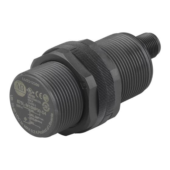
Plug and cable versions Housing Figure 1 - M18 Housing Status Indicator Sensitivity Figure 2 - M30 Housing Sensitivity Adjustment AC Models Programmable N.O. or N.C. )by selector switch back view) (2-wire device back view) Sensitivity Rockwell Automation Publication 875-UM001A-EN-P - March 2021... -
Page 8: 875F Dc Flat Cap
• Protection: reverse polarity, short circuit, and transients • Cable and pigtail M8 plug versions • Excellent EMC performance • IP65, IP66, IP67, IP68, and IP69K for hose-down applications • c-UL-us • Ecolab Rockwell Automation Publication 875-UM001A-EN-P - March 2021... - Page 9 Description Code Description Code Description N.O. PNP 34 mm (1.34 in.) 2 m (6.6 ft) PVC cable N.O. NPN 0.2 m (0.66 ft) PVC FP02 cable 4-pin DC pico N.C. PNP N.C. NPN Rockwell Automation Publication 875-UM001A-EN-P - March 2021...
-
Page 10: Io-Link Sensors
Analog output: In IO-Link mode, the sensor generates 16-bit analog process data output that represents the dielectric value that the sensor measures. Housing M18 Housing M30 Housing Item Description Sensitivity adjustment Yellow status indicator Green status indicator Sensing face Rockwell Automation Publication 875-UM001A-EN-P - March 2021... - Page 11 Output Type Code Description Code Description Code Description N.O. PNP 18 mm (0.71 in.) 2 m (6.6 ft) PVC cable N.O. NPN 30 mm (1.18 in.) DC micro connector N.C. PNP N.C. NPN Rockwell Automation Publication 875-UM001A-EN-P - March 2021...
- Page 12 Chapter 1 Product Overview Notes: Rockwell Automation Publication 875-UM001A-EN-P - March 2021...
-
Page 13: Configure With Io-Link
Allows you to configure sensors by modifying parameter settings. (page Diagnosis Provides information of operation status and sensor health diagnosis, and enables you to restore (page factory default settings and physically locate the sensor for troubleshooting. Rockwell Automation Publication 875-UM001A-EN-P - March 2021... -
Page 14: Common Tab
Displays the complete file name of the IODD that is assigned to the product. Document Version Displays the version control for the IODD. Date of Creation Displays when the IODD file was creation. Rockwell Automation Publication 875-UM001A-EN-P - March 2021... -
Page 15: Identification Tab
Hardware version of the 875 sensor that is provided as alphanumeric value Firmware Version Firmware revision of the875 sensor that is provided as numeric value. Observation Tab The Observation tab displays real-time device status. For more information, Appendix B on page Rockwell Automation Publication 875-UM001A-EN-P - March 2021... -
Page 16: Parameter Tab
Chapter 2 Configure with IO-Link Parameter Tab The Parameter tab allows you to configure the sensor. For more information, Appendix B on page Rockwell Automation Publication 875-UM001A-EN-P - March 2021... -
Page 17: Diagnosis Tab
The sensor logs how many minutes the sensor has been operational below the minimum temperature for the sensor, the maximum number of temperature [min] minutes to be recorded is 2,147,483,647. This parameter is updated once per hour and can be read from an IO-Link master. Rockwell Automation Publication 875-UM001A-EN-P - March 2021... - Page 18 Chapter 2 Configure with IO-Link Notes: Rockwell Automation Publication 875-UM001A-EN-P - March 2021...
-
Page 19: Switch Output Configuration
Push-Pull Input 6. EXT-Input divider EXT-Input Item Description Sensor front (see page Input selector (see page Logic function block (see page Timer (see page Output inverter (see page Output stage mode (see page Rockwell Automation Publication 875-UM001A-EN-P - March 2021... -
Page 20: Sensor Front
The switching information changes, when the measurement value passes the thresholds that are defined in setpoint SP1 and setpoint SP2, with rising or falling measurement values, considering the hysteresis. Hyst Hyst Window mode Sensor Sensing distance window Rockwell Automation Publication 875-UM001A-EN-P - March 2021... -
Page 21: Hysteresis Settings
In the logic function block, the selected signals from the input selector can be added a logic function directly without using a PLC - which makes decentral decisions possible. The logic functions available are AND, OR, XOR, and gated SR-FF. Rockwell Automation Publication 875-UM001A-EN-P - March 2021... -
Page 22: And Function
Gated SR-FF Function The function is designed to function as filling or emptying function with only two interconnected sensors. Truth Table Symbol & Flip-Flop ≥1 (1) X = No changes to the output. Rockwell Automation Publication 875-UM001A-EN-P - March 2021... -
Page 23: Timer
Each time a target is detected in front of the sensor the switching output generates a pulse of constant length on the leading edge of the detection. Presence of target One shot leading edge Rockwell Automation Publication 875-UM001A-EN-P - March 2021... -
Page 24: Output Inverter
In this function block, you can select how the switching outputs operate: • SO1: Disabled, NPN, PNP, or Push-Pull configuration. • SO2: Disabled, NPN, PNP, Push-Pull, External input (Active high/Pull- down), External input (Active low/pull up), or External Teach input. Rockwell Automation Publication 875-UM001A-EN-P - March 2021... -
Page 25: External Teach (Teach-By-Wire)
1. Select: 1=SSC1 or 2=SSC2 in the Teach-in Select 58(0x3A) or 255 = All SSC. 2. Change the Hysteresis if requested for SSC1 or SSC2. • SSC1 configuration 61(0x3D) Hysteresis 3(0x03). • SSC2 configuration 62(0x3D) Hysteresis 3(0x03). Rockwell Automation Publication 875-UM001A-EN-P - March 2021... -
Page 26: Two-Point Mode Procedure
3. #73 SP2 dynamic teach start 4. #74 SP2 dynamic teach stop 5. #64 Teach apply (optional command) Dynamic teach Sensor Command Sequence Sensing distance 1) “SP1 Dynamic Teach Start” 2) “SP2 Dynamic Teach Stop” 3) “Teach Apply” Rockwell Automation Publication 875-UM001A-EN-P - March 2021... -
Page 27: Windows Mode Procedure
3. #73 SP2 dynamic teach start 4. #74 SP2 dynamic teach stop 5. #64 Teach apply (optional command) Dynamic Sensor Command Sequence Sensing distance 1) “SP1 Dynamic Teach Start” 2) “SP2 Dynamic Teach Stop” 3) “Teach Apply” Rockwell Automation Publication 875-UM001A-EN-P - March 2021... - Page 28 Chapter 4 Teach Procedure Notes: Rockwell Automation Publication 875-UM001A-EN-P - March 2021...
-
Page 29: Local Or Remote Adjustment Selection
This preset is used for slow-moving objects with a low dielectric value such as detection of Plastic pellets plastic pellets. When this function is selected, the teach and potentiometer settings are optimized to low-range scaling. In this mode, the Filter Scaler is set to 100. Rockwell Automation Publication 875-UM001A-EN-P - March 2021... -
Page 30: Temperature Alarm Threshold
Average sensing conditions. • Short-term reliability and maintenance are expected due to environmental conditions. • Reliable detection can be expected with restricted environmental influence. Poor to not reliable working sensing conditions is expected. Rockwell Automation Publication 875-UM001A-EN-P - March 2021... -
Page 31: Quality Of Teach (Qot)
255 gives the minimum sensing frequency. Status Indication This parameter allows you to disable status indication in the sensor if you do not want the status indicators to illuminate in your application. Rockwell Automation Publication 875-UM001A-EN-P - March 2021... - Page 32 Chapter 5 Sensor-specific Adjustable Parameters Notes: Rockwell Automation Publication 875-UM001A-EN-P - March 2021...
-
Page 33: Non-Io-Link Sensors
Frequency of operating cycles (f) 10 Hz Indication for output ON Yellow status indicator Degree of protection IP67 (NEMA 1, 3, 4, 6, 13) • Operating: -25…+80 °C (-13…+176 °F) Temperature • Storage: -40…+85 °C (-40…+185 °F) Rockwell Automation Publication 875-UM001A-EN-P - March 2021... -
Page 34: 875F Dc Flat Cap
IP65, IP66, IP67, IP68 @ 1.3 m and 24 h; IP69K (NEMA 1, 2, 4, 4x, 5, 12) • Operating: -25…+80 °C (-13…+176 °F) Temperature • Storage: -40…+85 °C (-40…+185 °F) Humidity range Operating and storage: 35…95% Rockwell Automation Publication 875-UM001A-EN-P - March 2021... -
Page 35: Io-Link Sensors
Operating and storage: 35…95% Wiring Diagram 1 BN 4 BK 2 WH 3 BU Color Signal Description Brown 10…40V DC Sensor supply White Load Output 2/SIO mode/External input/External teach Blue Ground Black Load IO-Link/Output 1/SIO mode Rockwell Automation Publication 875-UM001A-EN-P - March 2021... - Page 36 Appendix A Specifications Notes: Rockwell Automation Publication 875-UM001A-EN-P - March 2021...
-
Page 37: Device Parameters
Read-only 2 = Out-of-specification UIntegerT 8 bit operating properly 3 = Functional-Check 4 = Failure Maintenance Required — Read-only — — OctetStringT 3 bytes Process-DataInput 40 (0x28) Read-only — — IntegerT 32 bit Rockwell Automation Publication 875-UM001A-EN-P - March 2021... -
Page 38: Ssc Parameters
1 = Single Point Mode UIntegerT 8 bit 2 = Window Mode 3 = Two Point Mode 875L-M8xx18: 6% 875L-N12xx18: 15% Hysteresis 2 3 (0x03) Read/write 1…100 UIntegerT 16 bit 875L-M16xx30: 7% 875L-N25xx30: 10% Rockwell Automation Publication 875-UM001A-EN-P - March 2021... -
Page 39: Output Parameters
8 bit 3 = XOR 4 = Gated SR-FF 1 = Inverted (Normal 0 = Not inverted (Normal Open) Polarity 2 8 (0x08) Read/write UIntegerT 8 bit Closed) 1 = Inverted (Normal Closed) Rockwell Automation Publication 875-UM001A-EN-P - March 2021... -
Page 40: Sensor-Specific Adjustable Parameters
(5) See Event Configuration on page (6) See Quality of Teach (QoT) on page (7) See Quality of Run (QoR) on page (8) See Filter Scaler on page (9) See Status Indication on page Rockwell Automation Publication 875-UM001A-EN-P - March 2021... -
Page 41: Diagnosis Parameters
0 = Disabled LED Indication 78 (0x4E) Read/write 1 = Enabled BooleanT 8 bit 1 = Enabled 0 = Disabled Location Indicator 94 (0x5E) Read/write 1 = Enabled BooleanT 8 bit 1 = Enabled Rockwell Automation Publication 875-UM001A-EN-P - March 2021... - Page 42 Appendix B Parameter Values Notes: Rockwell Automation Publication 875-UM001A-EN-P - March 2021...
-
Page 43: Index
37 diagnosis parameter 41 diagnosis tab 17 margin alarm 21 mode output stage 24 single-point 25 event configuration 30 switchpoint 20 external input 21 timer 23 external teach 25 two-point 26 windows 27 Rockwell Automation Publication 875-UM001A-EN-P - March 2021... - Page 44 35 filter 31 selector input 21 XOR function 22 sensor application setting 29 IO-Link 10 IO-Link specifications 35 non-IO-Link 7 specification 33 sensor front 20 sensor-specific adjustable parameter 29 sensor-specific adjustable parameter 40 Rockwell Automation Publication 875-UM001A-EN-P - March 2021...
- Page 45 Capacitive Sensors User Manual Rockwell Automation Publication 875-UM001A-EN-P - March 2021...
- Page 46 At the end of life, this equipment should be collected separately from any unsorted municipal waste. Rockwell Automation maintains current product environmental information on its website at rok.auto/pec. Allen-Bradley, expanding human possibility, and Rockwell Automation are trademarks of Rockwell Automation, Inc. EtherNet/IP is a trademark of ODVA, Inc.
Need help?
Do you have a question about the Allen-Bradley 875L AC and is the answer not in the manual?
Questions and answers