
Related Manuals for Stanley Avdel 73200


Summary of Contents for Stanley Avdel 73200
- Page 1 INSTRUCTION AND SERVICE MANUAL ORIGINAL INSTRUCTION Hydro-Pneumatic Power Tool 油空圧電動ツール 液压气动工具 73200 Structural Rivet Tool Hydro-Pneumatic Power Tool...
- Page 2 STANLEY Engineered Fastening. The information provided is based on the data known at the moment of the introduction of this product. STANLEY Engineered Fastening pursues a policy of continuous product improvement and therefore the products may be subject to change. The information provided is applicable to the product as delivered by STANLEY Engineered Fastening.
-
Page 3: Table Of Contents
O R I G I N A L I N S T R U C T I O N E N G L I S H CONTENTS SAFETY DEFINITIONS ..............................4 GENERAL SAFETY RULES ..................................4 PROJECTILE HAZARDS ....................................4 OPERATING HAZARDS .................................... -
Page 4: Safety Definitions
• Only qualified and trained operators must install, adjust or use the tool. • DO NOT use outside the design intent of placing STANLEY Engineered Fastening Blind Rivets. • Use only parts, fasteners and accessories recommended by the manufacturer. •... -
Page 5: Operating Hazards
O R I G I N A L I N S T R U C T I O N E N G L I S H 1.3 OPERATING HAZARDS • Use of the tool can expose the operator's hands to hazards, including crushing, impacts, cuts, abrasions and heat. Wear suitable gloves to protect hands. -
Page 6: Additional Safety Instructions For Pneumatic Power Tools
E N G L I S H O R I G I N A L I N S T R U C T I O N • Operate and maintain the assembly power tool for blind rivets as recommended in the instruction handbook, to prevent an unnecessary increase in vibration levels. -
Page 7: Specifications
2. SPECIFICATIONS 2.1 INTENT OF USE The hydro-pneumatic 73200 is designed to place Stanley Engineered Fastening lockbolt and breakstem fasteners. For a complete tool, order a base tool part number 73200-02000 and select a nose assembly from the Nose Assemblies section on page 11 to suit your application. -
Page 8: Tool Dimensions
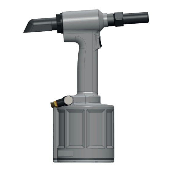
E N G L I S H O R I G I N A L I N S T R U C T I O N 2.3 TOOL DIMENSIONS Fig.1 All dimensions are shown in millimetres. -
Page 9: Putting In Service
O R I G I N A L I N S T R U C T I O N E N G L I S H 3. PUTTING IN SERVICE IMPORTANT - READ THE SAFETY RULES ON PAGE 4 & 6 CAREFULLY BEFORE PUTTING INTO SERVICE. Before Use •... -
Page 10: Operating Procedurce
E N G L I S H O R I G I N A L I N S T R U C T I O N 3.2 OPERATING PROCEDURCE IMPORTANT – Do not attempt to break off a pintail without the installation of a collar. This will cause the unsecured portion of the pintail to eject from the nose at a high speed and force. -
Page 11: Nose Assemblies
O R I G I N A L I N S T R U C T I O N E N G L I S H 4. NOSE ASSEMBLIES It is essential that the correct nose assembly is fitted prior to operating the tool. By knowing your original complete tool part number or the details of the fastener to be placed, you will be able to order a new complete nose assembly using the selection tables on page 11. -
Page 12: Standard Nose Assembly Selection
E N G L I S H O R I G I N A L I N S T R U C T I O N 4.2 STANDARD NOSE ASSEMBLY SELECTION The fasteners below can also be placed on the 73200 tool. It is essential that the correct nose assembly is fitted prior to operating the tool. -
Page 13: Accessories
O R I G I N A L I N S T R U C T I O N E N G L I S H 5. ACCESSORIES COLLAR SPLITTERS You can order collar splitters to cut the collars off placed Avdelok®. The small size shown below left is for cutting 3/16” and 1/4”... -
Page 14: Installation Instructions
E N G L I S H O R I G I N A L I N S T R U C T I O N 5.1 INSTALLATION INSTRUCTIONS BODY DISASSEMBLY • To fit these collar splitters, disconnect tool from air supply •... -
Page 15: Servicing The Tool
O R I G I N A L I N S T R U C T I O N E N G L I S H 6. SERVICING THE TOOL Regular servicing should be carried out and a comprehensive inspection performed annually or every 500,000 cycles, whichever is sooner. -
Page 16: Molykote® 55M Grease Safety Data
E N G L I S H O R I G I N A L I N S T R U C T I O N 6.4 MOLYKOTE® 55m GREASE SAFETY DATA First Aid SKIN: Flush with water. Wipe off. INGESTION: No first aid should be needed. -
Page 17: Service Kit
O R I G I N A L I N S T R U C T I O N E N G L I S H 6.6 SERVICE KIT For all servicing we recommend the use of the 73200 Maintenance Kit. Maintenance Kit 73200-99990 Part Number Description... -
Page 18: Dismantling Instructions
E N G L I S H O R I G I N A L I N S T R U C T I O N 6.8 DISMANTLING INSTRUCTIONS PREPARATION • Connect tool to air supply. Depress Trigger 29 and hold. •... -
Page 19: Protecting The Environment
O R I G I N A L I N S T R U C T I O N E N G L I S H Remove Head Piston 64 from Head 63. Remove Head Piston Seals 19, Anti-extrusion Rings 20 and Lip Seal 21 from •... - Page 20 E N G L I S H O R I G I N A L I N S T R U C T I O N BODY ASSEMBLY Fit Head Vice Jaw* to Head 63 and use soft jaws to hold the Head Vice Jaw in the inverted orientation. •...
-
Page 21: General Assemblies
O R I G I N A L I N S T R U C T I O N E N G L I S H 7. GENERAL ASSEMBLIES 7.1 GENERAL ASSEMBLY OF BASE TOOL 73200-02000... -
Page 22: General Assembly Parts List
E N G L I S H O R I G I N A L I N S T R U C T I O N 7.2 GENERAL ASSEMBLY PARTS LIST Parts List for 73200-02000... -
Page 23: Priming
O R I G I N A L I N S T R U C T I O N E N G L I S H 8. PRIMING Priming is ALWAYS necessary after the tool has been dismantled and prior to operating. It may also be necessary to restore the full stroke after considerable use, when the stroke may have been reduced and fasteners are not now being fully placed by one operation of the trigger. -
Page 24: Priming Ports
E N G L I S H O R I G I N A L I N S T R U C T I O N 8.4 PRIMING PORTS Fig. 5 8.5 STROKE SETTING The Pull Stroke Setter is used to advance the Head Piston 64 to full stroke. The external threads on the Pull Stroke Setter wind into the Head 63, pushing the Head Piston back. - Page 25 O R I G I N A L I N S T R U C T I O N E N G L I S H PREPARATION Ensure tool is disconnected from air supply. Remove all bleed screws 1 and seals 5. Using soft jaws to hold the tool Handle, position the tool in the nose-down orientation.
-
Page 26: Top-Up Priming Procedure
E N G L I S H O R I G I N A L I N S T R U C T I O N Using a 27mm A/F spanner, Starter Nut and both sides of the Return Stroke Setter*, wind the Head Piston 64 forward to 0mm stroke, applying pressure to the plunger at all times. - Page 27 O R I G I N A L I N S T R U C T I O N E N G L I S H With the Head Piston at 21mm stroke, remove Pull Stroke Setter. Remove the Priming Syringe* with Extension* and reseal this port. RETURN SIDE PRIMING Connect tool to air supply.
-
Page 28: Fault Diagnosis
E N G L I S H O R I G I N A L I N S T R U C T I O N 9. FAULT DIAGNOSIS 9.1 SYMPTOM POSSIBLE CAUSE AND REMEDY SYMPTOM POSSIBLE CAUSE REMEDY PAGE REF. Adjust air pressure Reduced air pressure Short stroke or... -
Page 29: Ec Declaration Of Conformity
O R I G I N A L I N S T R U C T I O N E N G L I S H 10. EC DECLARATION OF CONFORMITY We, Stanley Engineered Fastening, Stanley House, Works Road, Letchworth Garden City, Hertfordshire, SG6 1JY UNITED KINGDOM, declare under our sole responsibility that the product: Description:... -
Page 30: Declaration Of Conformity
O R I G I N A L I N S T R U C T I O N 11. UK DECLARATION OF CONFORMITY We, Stanley Engineered Fastening, Stanley House, Works Road, Letchworth Garden City, Hertfordshire, SG6 1JY UNITED KINGDOM, declare under our sole responsibility that the product:... -
Page 31: Protect Your Investment
Engineered Fastening location. STANLEY Engineered Fastening will then replace, free of charge, any part or parts found by us to be defective due to faulty material or workmanship, and return the tool prepaid. This represents our sole obligation under this warranty. - Page 32 英語 取扱説明書原文からの翻訳 ©2021 Stanley Black & Decker inc. 無断転載禁止。 本説明書で示された情報は、STANLEY Engineered Fasteningからの事前の明示および書面による許可なしに、い かなる手段 (電子的または機械的) によっても複製かつまたはいかなる方法による公開も許可しません。示された 情報は、本製品の紹介時点で知られたデータに基づいています。STANLEY Engineered Fasteningは絶え間ない製 品開発のポリシーを遂行するため、製品の仕様は変更の対象となる場合があります。示された情報は、STANLEY Engineered Fastening によって納品された時点で製品に適用されます。そのため、STANLEY Engineered Fasteningは、製品本来の仕様からの逸脱による損傷について一切の責任を負いません。 利用可能な情報は最大限の注意を払って整理しました。しかし、STANLEY Engineered Fasteningは情報のいかな る誤りおよびそれが原因で生じる結果に関しても責任を受け入れません。STANLEY Engineered Fastening は、第 三者によって行われた行為によって引き起こされた損傷についての責任を受け入れません。STANLEY Engineered Fasteningが使用するワーキングネーム、商号、登録商標などは、商標保護の観点から法律に準拠するものであり、 自由に使用することはできません。...
- Page 33 取扱説明書原文の翻訳 英語 目次 安全の定義 .................................. 34 一般安全ルール .......................................34 発射の危険 .........................................34 操作上の危険 ......................................35 繰返し動作の危険 ....................................35 アクセサリの危険 ....................................35 作業場の危険 ......................................35 ノイズの危険 ......................................35 振動の危険 .........................................36 空圧電動ツールに関する追加安全指示 ............................36 仕様 .................................... 37 用途 ..........................................37 ツールの仕様 ......................................37 工具動作 ........................................38 作動 .................................... 39 エア供給 ........................................39 操作手順 ........................................40 ノーズアセンブリ...
-
Page 34: 安全の定義
警告: この表示を無視した場合、人が死亡または重傷を負う可能性がある潜在的な危険な状況を示します。 注意: この表示を無視した場合、経度または中程度の障害を負う場合がある潜在的な危険な状況を示します。 注意: 表示を無視した場合、潜在的な危険な状況を示す安全上の警告表示なしで使用すると、資産が損傷を受け る場合があります。 本製品の不適切な操作または保守を行った場合は、重傷を負ったり物的損害が発生する可能性があります。本機を 使用する前に、すべての警告および操作の説明を読み理解してください。電動ツールを使用するときは、怪我のリ スクを減らすために基本的な安全上の注意を必ず守る必要があります。 今後も参考にして頂くため、警告と取扱い説明書はすべて保管してください 1.1 一般安全ルール • 複数の危険な状況が存在する場合は、ツールの取り付け、操作、修理、保守、アクセサリの交換、またはツー ルの近くで作業する前に、安全上の注意事項を読んで理解してください。これを怠った場合、重大な人身事故 が発生する可能性があります。 • 資格を有しトレーニングを受けたオペレータのみが、ツールの取り付け、調整、使用を行えます。 • 位置決め STANLEY 締付け工具ブラインド リベットの設計意図を外れた使用はしないでください。 • 製造会社が推奨する部品、締付け具、アクセサリのみを使用してください。 • ツールを改造しないでください。改造した場合、安全対策の有効性が低下し、オペレータへのリスクが高まる 可能性があります。お客様が本機を改造した場合、すべての責任はお客様が負うものとなり、すべての保証は 無効となります。 • 安全上の指示を破棄することなく、オペレータに渡してください。 • ツールが破損している場合は使用しないでください。 • 使用する前に、可動部品の不整合や結合、部品の損傷、それ以外にツールの操作に影響を及ぼす状態がないか を確認してください。損傷がある場合は、使用する前にツールを修理してください。使用する前に調整キーま たはレンチを取り外してください。 • ツールは定期的に点検して、ISO 11148のこの部分に必要な定格とマーキングがツールに判読可能にマークさ... -
Page 35: 操作上の危険
取扱説明書原文の翻訳 英語 • マンドレルコレクターを取り付けずにツールを使わないでください。 • ツールの前面からマンドレルが強制的に排出される可能性があることを警告します。 • 人に向けての本機の操作は行わないでください。 1.3 操作上の危険 • このツールを使用する場合、圧搾、衝撃、切り傷、擦り傷、熱など、オペレータは手を損傷する可能性があり ます。適切な保護手袋を着用して手を保護してください。 • オペレータと保守担当者は、ツールの大きさ、重量、パワーを物理的に扱える必要があります。 • ツールを正しく保持します。 通常または突然の動きに対処する準備をし、両手が使える状態にします。 • 本機のハンドルの部分は乾いたきれいな状態を保ち、油やグリスの付着がないようにしてください。 • ツールを操作するときは、バランスのとれた姿勢を維持し、足場を確保してください。 • エア供給が中断した場合は、スタートアンドストップ (開始停止) 装置を解除してください。 • 製造元が推奨する潤滑剤のみを使用してください。 • 油圧油に触れることは避けてください。触れてしまった場合は、発疹が発生しないように、完全に洗い流して ください。 • 油圧オイルおよび潤滑油の製品安全データシートは、ツールの製造元に請求して入手してください。 • ツールの通常の動きまたは予期しない動きに対処することができない可能性がある不適切な姿勢での操作は避 けてください。 • ツールがサスペンション装置に固定されている場合は、確実に固定されていることを確認してください。 • ノーズ装置が取り付けられていない場合、つぶされたりつままれたりする危険に注意してください。 •... -
Page 36: 振動の危険
英語 取扱説明書原文からの翻訳 1.8 振動の危険 • 振動にさらされると、手や腕の神経や血液供給に障害を引き起こす可能性があります。 • 寒い場所で作業するときは暖かい服を着て、手を暖かく乾いた状態に保ってください。 • 指や手の皮膚のしびれ、うずき、痛み、または白化を経験した場合は、ツールの使用を中止し、雇用主に連絡 して医師に相談してください。 • 軽量のグリップを使用してツールを支持できるため、スタンド、テンショナー、またはバランサーでツールの 重量を支えます。 • 取扱説明書に記載されている通りに、ブラインドリベット用アセンブリ電動ツールを操作・メンテナンスする ことで、振動レベルの不必要な上昇を防ぐことができます。 • 取扱説明書に記載されている通りに、消耗品や挿入工具を選択、メンテナンス、交換することで、振動レベル の不必要な上昇を防ぐことができます。 • 握る力が大きいほど振動の危険性が高くなるため、必要な手の反力を考慮して、軽くかつ安全にツールを握っ てください。 1.9 空圧電動ツールに関する追加安全指示 • 運転時の供給空気圧は、7 bar (102 PSI) を超えてはなりません。 • 加圧エアは重傷を引き起こす可能性があります。 • 本機を人がいない状態で動作させないでください。ツールを使用していないとき、アクセサリを交換する前、 または修理を行うときは、エアホースを外してください。 • 自分や他の人にエアを向けないでください。 • ホースを急に動かすと、重傷を負う可能性があります。ホースや継手の損傷や緩みがないか常に確認してくだ さい。... -
Page 37: ツールの仕様
取扱説明書原文の翻訳 英語 2. 仕様 2.1 用途 油空圧73200は、Stanley Engineered Fasteningのロックボルトとブレークステム締付け具を取り付けるように設計 されています。 ツール一式が必要な場合は、ベースツール部品番号73200-02000を注文し、41ページのノーズアセンブリの一覧 からお客様の用途に適したノーズアセンブリを選択してください。 常に安全上の注意事項に従う必要があります。 濡れた状態や可燃性の液体や気体のある場所では使用しないでください。 2.2 ツールの仕様 空気圧 最小 - 最大 5-7 bar (73-102 lbf/in2) 必要な自由空気量 @ 5 bar 14.2 リットル (73 Ibf/in2) @ 7 bar 19.9 リットル (102 Ibf/in2) ストローク... -
Page 38: 工具動作
英語 取扱説明書原文からの翻訳 2.3 工具動作 Fig.1 寸法はすべてミリメートルで示されます。... -
Page 39: エア供給
取扱説明書原文の翻訳 英語 3. 作動 重要 - ご使用になる前に、34ページと36ページの安全規則をよくお読みください。 使用の前に • 適切なサイズのノーズ装置を選択し取り付けてください。 • 位置決めツールをエア供給に接続してください。トリガーを引いたり離したりして、引込みと戻りのサイクル をテストします。 注意: インストールツールが正しく機能するためには、適切な供給圧力が重要です。適切な圧力が得られない場 合、人身事故や機器の損傷を招く恐れがあります。供給圧力が、位置決めツールの仕様の範囲を超えないよう にしてください。 3.1 エア供給 • 本機は最適圧力5.5 barの圧縮エアで操作します。メインの空気供給には、圧力調整器とフィルタリングシステ ムを使用することをお勧めします。これらは、ツールの寿命を最大限に伸ばし、ツールのメンテナンスを最小限に 抑えるために、ツールから3メートル以内に取り付けてください(下図参照)。 注意: キャビネットの圧力調整器は5.25 barに設定されます。 注意: いかなる場合でも圧力調整器を調整しないでください。 注意: キャビネットの安全バルブは5.25 - 5.30 barに設定されます。 注意: いかなる場合でも安全バルブを調整しないでください。 エア供給ホースには、システムで生成される最大圧力の150%または10 barのどちらか高い方の最小作業効果的圧力 レートが必要です。エアホースはオイル抵抗があり、外面は摩耗抵抗があるため、操作条件がホースの損傷を招く 場合がある場所では外側を保護する必要があります。すべてのエアホースの最小内径は、6.4 mm(1/4インチ)以 上必要です。... -
Page 40: 操作手順
英語 取扱説明書原文からの翻訳 3.2 操作手順 重要 - カラーを取り付けずにピンテールを取り外さないでください。取り外した場合、ピンテールの固定されてい ない部分が高速かつ高圧でノーズから排出されます。 ロックボルト製品を取り付ける場合: 正しいノーズアセンブリが取り付けられていることを確認 します。 ツールをエア供給に接続します。 Avdelok® ピンを施工穴に押し込みます。 (図に示す方向に合わせて)ピンの上にカラーを取り付け ます。 施工穴に対してピンのヘッドを保持し、突出しているピン テールにツールを押し込みます。 トリガーを完全に押し下げます。1回のサイクルで、カラー はピンのロック溝にスウェージされ、ピンはブレーカ溝で 切断されます。 Fig.3 トリガーを解除します。ツールがカラーから取り外され、 ピンテールが後方に排出されて、ツールのサイクルは完了 します。 ブレークステム製品を取り付ける場合: 正しいノーズアセンブリが取り付けられていることを確認します。 ツールをエア供給に接続します。 締付け具ステムをツールのノーズに挿入します。 突出した締付け具が直角に施工穴に入るように、締付け具とともにツールを施工穴に挿入します。 トリガーを完全に押し下げます。ツールのサイクルは締付け具をブローチします。 トリガーを解除します。ツールのサイクルが完了します。... -
Page 41: ノーズアセンブリ
取扱説明書原文の翻訳 英語 4. ノーズアセンブリ 本機を使用する前に、正しいノーズアセンブリを取り付けることが重要です。独自のツール一式の部品番号や位置 決めする締付け具の詳細を知ることで、41ページの選択表を使い、新しいノーズアセンブリを注文することがで きます。 4.1 AVDELOK® ノーズアセンブリの種類 Avdelok® ノーズ機器には、4つのタイプがあります。本機を使用する前に、正しいノーズアセンブリを取り付ける ことが重要です。 AVDELOK® ノーズアセンブリの種類 ノーズ機器 Ø 説明 部品番号 イン イン イン イン チ チ チ チ 縦型フラット 3/16" 0.812 0.625 2.120 1.000 07200-02500 * 横型フラット 3/16" 0.812 0.625 2.120 1.000 07200-02700 * 縦型フラット... -
Page 42: 標準ノーズアセンブリの種類
英語 取扱説明書原文からの翻訳 4.2 標準ノーズアセンブリの種類 以下の締付け具を73200ツールに取り付けることもできます。本機を使用する前に、正しいノーズアセンブリを取 り付けることが重要です。 標準ノーズアセンブリの種類 締付け具 ノーズ機器 名前 Ø 説明 部品番号 データシート07900-00905を参照してください。 AVBOLT® 3/16" (4.8 mm) 07220-08100 データシート07900-00905を参照してください。 1/4" (6.4 mm) 07220-07500 ノーズチップの種類については、データシート07900- 11 mm 標準 AVSEAL® II 07220-06600 00840を参照してください。 ノーズチップの種類については、データシート07900- 12 mm 標準 07220-06700 00840を参照してください。 ノーズチップの種類については、データシート07900- 13 mm 低圧 07220-06600 00840を参照してください。... -
Page 43: 付属品
取扱説明書原文の翻訳 英語 5. 付属品 カラースプリッター 取り付けたAvdelok® のカラーを切断するためにカラースプリッターを注文することができます。以下の左図 は、3/16”と1/4”カラー切断用の小型カラースプリッターです。以下の右図は、5/16”と3/8”カラー切断用の大型カラ ースプリッターです。 太字の寸法の単位は、mmです。その他の寸法の単位はインチです。 カラースプリッター - 構成部品番号 3/16" カラース 1/4" カラース 5/16" カラース 3/8" カラース 部品番号 説明 数量 プリッター プリッター プリッター プリッター 07500-06800 07500-06900 07220-03700 07220-03900 ソケットヘッドキャップスクリュー 07001-00004 07001-00004 07001-00142 07001-00142 スリーブ 07210-02012 07210-02012 ブレードピン... -
Page 44: 取り付け手順
英語 取扱説明書原文からの翻訳 5.1 取り付け手順 ボディの分解 • これらのカラースプリッターを取り付けるには、ツールを エア供給から切り離します。 • ピンテールディフレクター47を取り外します。 • 取り付けられている場合、ノーズアセンブリを取り外しま す。 • カラースプリッターのカムフェース、ベアリングフェー ス、他の可動部品にMoly Lithiumグリースを塗布します。 • ツールの後方から10mm A/F”六角レンチを使ってヘッドピ ストンを保持しながら、スパナを使ってヘッドピストンの 上にコレットアダプターを締め付けます。 • コレットアダプターの上にアンビルアダプターを押し込 み、ネジ留めします。スパナを使って締め付けます。 • 組み立てたカラースプリッターをアンビルアダプターに挿 入し、コレットアダプターの端にネジ留めします。スパナ を使ってアンビルアダプターの上にノーズ止めナットを締 め付けます。 • 動作させるためにカラースプリッターをカラーの上に押し 込み、トリガーを引きます。 • 5/16”または3/8”Avdelok® を切断するには、07220-03700または07220-03900カラースプリッターを使用しま す。アダプターキットは不要です。 • ヘッドバイスジョー*をヘッド63に取り付け、ソフトジョーを使って逆方向にヘッドバイスジョーを保持しま す。 •... -
Page 45: ツールの整備
取扱説明書原文の翻訳 英語 6. ツールの整備 定期的な整備を行い、総合的な検査を年に1回または500,000サイクル毎のいずれか早い方の時点で行う必要があり ます。 注意: ツールの非金属部分の洗浄には、溶剤やその他の刺激の強い薬品を絶対に使用しないでください。これら の薬液は部品に使用されている材料を劣化させる場合があります。 注意: 保守作業を始める前に、作業工程で蓄積した危険な物質をすべて取り除きます。 注意: 雇用者は、適切な人員にツールのメンテナンス指示を与えることを保証する責任を負います。 注意: 適切に訓練されていないオペレーターは、ツールのメンテナンスあるいは修理に関与することは認められ ません。 注意: ツールに損傷や故障がないか定期的に検査してください。 注意: 安全に関する指示(34 ~ 36ページ)を読んでください。 6.1 毎日の点検 • 毎日の使用前、または本機を初めて使用する際には、洗浄剤を数滴注ぎ、注油器がエア供給に取り付けられて いない場合にはツールの給気口に少量の潤滑油を注入してください。本機を連続使用する場合は、エアホース をメインのエア供給から切り離し、本機を2、3時間毎に潤滑します。 • エア漏れがないか確認します。損傷している場合は、ホース、カップリングを交換してください。 • オイル漏れがないか確認します。 • 圧力レギュレータにフィルタがない場合は、エアホースを本機に接続する前にエアラインを抽気して蓄積した 汚れまたは水を取り除きます。フィルタがある場合は排出します。 • ノーズアセンブリが締付け具に正しく取り付けられていることを確認します。 • ディフレクター47が本機に取り付けられていることを確認します。 • ツールのストロークが最低限の仕様を満たしていることを確認します(37ページ)。56ページと57ペ... -
Page 46: Molykote® 55Mグリースの安全性データ
英語 取扱説明書原文からの翻訳 6.4 MOLYKOTE® 55mグリースの安全性データ 応急処置 皮膚: 水で洗い流します。拭き取ります。 経口摂取: 応急手当ては不要。 目: 水で洗い流します。 火災 引火点: 101.1°C超。(閉じたカップ) 爆発性: いいえ 適切な消火メディア: 二酸化炭素泡、乾燥パウダーあるいは細かな散水。 火災に露出されたコンテナを冷やすために水を使用することができる。 環境 排水溝や地表水に大量に入れないこと。 クリーンアップの方法:ふたをした適切な容器にこすり落とし、置く。こぼれた製品は、非常に滑りやすい表面を 作り出す。 水生生物に有害で、水生環境に長期的な悪影響を及ぼす可能性がある。しかし、製品の物理的形状と水に溶けない 性質のため、生物学的利用能はごくわずかである。 取り扱い 一般的な換気が推奨される。皮膚や目に触れないようにする。 保管 酸化剤の近くに保管しない。コンテナを閉め、水または湿気から遠ざけて保管する。 6.5 MOLYKOTE® 111グリースの安全性データ 応急処置 皮膚: 応急手当ては不要。 経口摂取: 応急手当ては不要。 目: 応急手当ては不要。 吸入: 応急手当ては不要。... -
Page 47: サービスキット
取扱説明書原文の翻訳 英語 6.6 サービスキット すべてのサービスには、73200保守キットの使用をお勧めします。 保守キット73200-99990 部品番号 説明 部品番号 説明 07900-01040 エアピストンロッドブレット シールハウジングプッシュロッド 07900-01054 07900-01041 ベースプレートエクストラクター シールリテーナーレンチ 07900-01055 07900-01042 ハンドル止めナットレンチ スライドオフセットハンドル 07900-00427 07900-00043 ヘッドピストンブレット 07900-00151 T型ハンドルエクステンション 07900-01043 ヘッドピストンフロントシールスリーブ トリガーバルブエクストラクター 07900-00692 07900-01044 ヘッドピストンリアシールスリーブ 07900-00158 2 mmピンパンチ 07900-01045 ヘッドピストンシールガイド グリース - MOLYLITHIUM EP 3753 07992-00020 07900-01046 ヘッドバイスジョー... -
Page 48: 取り外しの手順
英語 取扱説明書原文からの翻訳 6.8 取り外しの手順 準備 • ツールをエア供給に接続します。 • トリガー29を引いて、保持します。 • エア供給を取り外し、トリガー29を解除します。 • ディフレクター47、止めナット49、アダプターリング50、アダプター48を取り外します。 操作バルブ • 22mm A/Fスパナまたはソケットを使ってスイベルボルト44を取り外し、スイベル43を取り外します。スイベ ルボルトから「O」リング4を取り外します。 • Use 6mm A/F六角レンチを使って、バルブリテーナー40を取り外します。「O」リング7を取り外します。 • バルブスプール39をボディ65の外に押し出します。「O」リング11を取り外します。 • バルブボディ42をボディ65の外に押し出します。「O」リング10および11を取り外します。 ボディアセンブリ • ヘッドバイスジョー*をヘッド63に取り付け、ソフトジョーを使って逆方向にヘッドバイスジョーを保持しま す。 • ロックナットソケット*を使ってロックナット38を取り外します。必要な場合、10mm A/F六角レンチを使って ベースプレート32が回転しないようにします。 • ベースキャップ31とガスケット36を取り外します。 • 保持リング25と消音器37を取り外します。 • ベースプレート32をボディ65に押し込み、保持リング24を取り外します。 •... -
Page 49: 環境保護
取扱説明書原文の翻訳 英語 エアピストンロッドエンド59からベアリングリング60を取り外します。 • 4mm A/F六角レンチをエアピストンロッド58に取り付けて、14mm A/Fスパナ、または5mm A/F六角レンチを 使ってエアピストンロッド59を取り外します。 • リターンピストンエクストラクターを使ってリターンピストン57を取り外します。リターンピストンからリッ プシール14を取り外します。 • ヘッドバイスジョー*を取り外します。ソフトジョーを使ってツールのハンドルを保持し、ツールを下に向けま す。 • 48mm A/Fスパナを使って、エンドキャップ51を取り外します。エンドキャップからベアリングリング53、ワ イパー22、「O」リング6を取り外します。 • ヘッド63からヘッドピストン64を取り外します。ヘッドピストンからヘッドピストンシール19、はみ出し防止 リング20、リップシール21を取り外します。 • シールハウジングプッシュロッド*を使って、シールハウジング52を取り外します。シールハウジングからリッ プシール17、ベアリングリング54、ワイパー18、「O」リング23を取り外します。 6.9 環境保護 適用される廃棄規制への適合を保証します。人や環境を危険にさらさないように、承認された廃棄物施設またはサ イトですべての廃棄物を処分してください。 6.10 組み立て手順 • すべてのOリングとシールを新品に交換し、空圧シールはMolykote® 55mグリース、油圧シールはMolykote® 111で潤滑してください。 ヘッドアセンブリ • ソフトジョーを使ってツールのハンドルを保持し、ツールを下に向けます。 • ベアリングリング54、リップシール17、ワイパー18、「O」リング23をシールハウジング52に取り付けます。 •... - Page 50 英語 取扱説明書原文からの翻訳 • ベアリングリング60をエアピストンロッドエンド59に取り付けます。 • エアピストンロッドブレット*をエアピストンロッド58に取り付けて、総組立図に示す方向と順番に従って、プ ルピストン56、リップシール14、シール止め、61、リップシール15、ベアリングリング62を取り付けます。 • エアピストンロッドアセンブリをヘッド63に挿入します。 • リップシール16と「O」リング12をシールリテーナー55に取り付けます。 • シールリテーナー55のネジ山にLoctite® 243*を塗布し、シールリテーナーレンチ*を使ってヘッド63を回転し ます。 • エアピストンロッドブレット*を取り外します。 • 2つの「O」リング13をヘッド63に取り付けます。 • トリガーバルブエクストラクター*を使って、トリガーバルブ28を取り付けます。 • トリガー29を取り付けて、トリガーピン30をヘッド63に挿入します。 • ヘッドバイスジョー*を取り外します。ソフトジョーを使ってツールのハンドルを保持し、ツールを下に向けま す。 • 4つのブリードスクリュー1と4つの接合シール5をシールブリードポートに取り付けます。 ボディアセンブリ • ヘッドバイスジョー*をヘッド63に取り付け、ソフトジョーを使って逆方向にヘッドバイスジョーを保持しま す。 • ボディ65をヘッド63に取り付けます。 • ハンドル止めナット34のネジ山にLoctite® 243*を塗布し、ハンドル止めナットレンチ*を使ってハンドル63を 回転します。 • エアピストンロッド58のネジ山にLoctite® 243*を塗布し、エアピストンロッドでエアピストンコネクタ41を回 転します。エアピストンロッドには4mm A/F六角レンチ、エアピストンコネクタには14mm A/Fスパナを使っ...
- Page 51 取扱説明書原文の翻訳 英語 • 2つの「O」リング4をスイベルボルト44に取り付けます。 • スイベル43をスイベルボルト44に取り付けます。 • スイベルボルト44のネジ山にPTFEテープを貼り、22mm A/Fスパナまたはソケットを使って、スイベルボルト を回転してボディ65に取り付けます。 • アダプター48、アダプターリング50、止めナット49、 ディフレクター47を取り付けます。 * 73200サービスキットに含まれます。完全なリストについては、47ページを参照してください。 太字の品目番号については、総組立図と部品表を参照してください(52~53ページ)。...
-
Page 52: 全体的な構成
英語 取扱説明書原文からの翻訳 7. 全体的な構成 7.1 ベースツール73200-02000総組立図... -
Page 53: 総組立図の部品表
取扱説明書原文の翻訳 英語 7.2 総組立図の部品表 73200-02000用部品表... -
Page 54: プライミング
英語 取扱説明書原文からの翻訳 8. プライミング ツールを分解した後には、運転に先立って必ずプライミングが必要です。また、ストロークが縮小され、トリガー を1度操作しても締付け具が完全に取り付けられていない場合、十分なストロークを回復するために、かなりの回数 使用する必要がある場合があります。 8.1 オイル詳細 プライミングで推奨されるオイルは、0.5リットル(部品番号07992-00002)、または1ガロンのコンテナ(部品番 号07992-00006)で利用可能なHyspin® VG32です。下記の安全データを参照してください。 8.2 HYSPIN® VG 32オイルの安全性データ 応急処置 皮膚: すみやかに石鹸と水で肌を徹底的に洗浄すること。日常的な接触の場合、応急手当は必要ありません。短時間の接 触の場合、応急手当は必要ありません。 経口摂取: 直ちに医師の診察を受けてください。吐かせないでください。 目: 数分間水で直ちに洗浄します。一次刺激原ではありませんが、次の接触で小さな刺激が生じることがあります。 火災 引火点:232°C。可燃性に分類されません。 適切な消火メディア: CO2、乾燥粉末、泡あるいは水霧。ウォータージェットは使用しないでください。 環境 廃棄物処理: 許可されたサイトで認可されたコントラクターによって処分を行います。焼却可能。中古製品は埋め立 てが可能です。 漏出: 排水管、下水管および水道に入らないようにしてください。吸収材で吸収させます。 取り扱い 目の防護具、不浸透性グローブ(例えばPVCの)およびプラスチックエプロンを着用します。十分換気されたエリア の中で使用します。 保管 特別な注意はありません。 8.3 プライミングキット 73200サービスキットには、ツールのプライミングに必要なすべての部品が含まれています。しかし、必要な場... -
Page 55: プライミングポート
取扱説明書原文の翻訳 英語 8.4 プライミングポート Fig. 5 8.5 ストローク設定 ヘッドピストン64をフルストロークさせるために、プルストロークセッターを使用します。プルストロークセッタ ーの外側の雄ネジをヘッド63内に回転し、ヘッドピストンの後方に押し込みます。ヘッドピストンが完全に前方に 移動し、逆側を使用するときにヘッドピストンが嵌合しないように、プルストロークセッターの片側のみがヘッド 内に回転します。ヘッド内で停止するまでプルストロークセッターを回転させると、可能なストロークの半分まで ヘッドピストンが進みます。次にプルストロークセッターを回して取り外し、逆側をヘッド内に回転させてストロ ークを完了します。 ヘッドピストン64を完全に前方まで引くために、リターンストロークセッターを使用します。雌ねじはヘッドピス トンまで回転し、前方まで引き出しますが、リターンストロークセッターはヘッド63で停止します。ヘッドピスト ンがフルストロークし、逆側を使用するときにヘッドが嵌合しないように、リターンストロークセッターの片側の みがヘッド内に回転します。ヘッド内で停止するまでリターンストロークセッターを回転させると、可能なストロ ークの約半分までヘッドピストンが戻ります。次にリターンストロークセッターを回して取り外し、逆側をヘッド 内に回転させて完全に前方位置まで戻ります。 いずれかのセッターを使用する場合、ヘッドピストンを回転させないでください。必要な場合、回転しないように 10mm A/F六角レンチをヘッドピストンの後方に取り付けてください。スターターナットがリターンストロークセ ッターに嵌合できるように、ヘッドピストンの前方に移動する必要がある場合があります。 8.6 初回プライミング手順 ツールのすべてのオイルが空になった場合、以下に示すツールの分解・保守の手順に従ってください。ツールのス トロークが不足している場合、57ページの補充プライミング手順に従ってください。 次のハイパーリングをクリックするか、QRコードをスキャンして、本機の初回プライミング手順の動画をご覧くだ さい。 http://youtu.be/k4g9iT4hhI8 * 以下の箇条書きの手順は、プライミング動画の関連セクションの各手順と関連しています。 * 73200サービスキットに含まれます。完全なリストについては、47ページを参照してください。 太字の品目番号については、総組立図と部品表を参照してください(52~53ページ)。... - Page 56 英語 取扱説明書原文からの翻訳 準備 ツールがエア供給から取り外されていることを確認します。 すべてのブリードスクリュー1とシール5を取り外します。 ソフトジョーを使ってツールのハンドルを保持し、ツールを下に向けます。 プルサイドのプライミング ツールがエア供給から取り外されていることを確認します。 プライミング前に、すべてのブリードスクリューを取り外します。 27mm A/Fスパナとリターンストロークセッター*を使用して、ヘッドピストン64を完全に前方に移動させま す。リターンストロークセッターを取り外します。 エクステンション*をプライミングシリンジ*の1つに取り付けます。 両方のプライミングシリンジに約30 mlのオイルを充填し、シリングからエアを除去します。 下部プルブリードポートにプライミングシリンジ*を取り付けます。 上部プルブリードポートにエクステンション付きプライミングシリンジ*を取り付けます。 2番目のシリンジの気泡がなくなる、またはオイルが5 ml以下に減少するまで、1番目のシリンジからオイルを 排出します。 1番目のシリンジの気泡がなくなる、またはオイルが5 ml以下に減少するまで、2番目のシリンジからオイルを 排出します。 気泡がなくなるまで、上記の2つの手順を繰り返します。 各シリンジ間のオイル量を一定にします。オイルとエアを含め、プランジャーは、各シリンジで25 mlの容量を 超えないようにする必要があります。 ツールをエア供給に接続します。 トリガーを押したままにします。これで、エアピストン33がプルストロークの終端になります。 エア供給からツールを取り外します。 下部プルブリードポートからプライミングシリンジ*を取り外して、このポートを再封します。 27mm A/Fスパナとプルストロークセッター*の両側を使って、ヘッドピストン64を21 mmストロークに後方に 回転して、常にプランジャーに圧力をかけます。これで、ヘッドピストンが後方に押されるため、気泡がシス テムに吸い込まれません。 ヘッドピストンを21 mmストロークにして、プルストロークセッターを取り外します。 エクステンション*付きプライミングシリンジを取り外して、このポート再封します。 リターンサイドのプライミング ツールがエア供給から取り外されていることを確認します。...
-
Page 57: 補充プライミング手順
取扱説明書原文の翻訳 英語 ツールをエア供給に接続します。これで、エアピストン33がリターンストロークの終端になります。 エア供給からツールを取り外します。 エクステンション*付きプライミングシリンジを取り外して、このポート再封します。 27mm A/Fスパナ、スターターナット、リターンストロークセッター*の両側を使って、ヘッドピストン64を0 mmストラークに前方に回転して、常にプランジャーに圧力をかけます。これで、ヘッドピストンが前方に引 き出され、気泡がシステムに吸い込まれません。 ヘッドピストンが完全に前方に移動し、適正な圧力がプランジャーにかかり、停止するまでシリンジからオイ ルが排出されます。約0.5 mlがシリンジからツールに押し出されます。 リターンストロークセッターを取り外します。 プライミングシリンジ*を取り外して、このポート再封します。 引込みと戻りのテスト ヘッドピストン64の終端からヘッド63の前面までの距離を測定します。 ツールをエア供給に接続します。 ツールの電源を入れ直します。ヘッドピストンの終端からヘッドの前面までの距離を測定します。ヘッドピス トンのストロークが21 mmであり、ヘッドピストンがサイクルの最後で完全に戻ることを確認します。そうで ない場合は、57ページの補充プライミング手順に従ってください。 エア供給からツールを取り外します。これでツールはプライミングされました。 8.7 補充プライミング手順 ツールのストロークが不足している場合、これらの指示に従ってください。ツールのすべてのオイルが空になって いる場合、以下に示すツールの分解・保守の手順など、55ページの初回プライミング手順に従ってください。 次のハイパーリングをクリックするか、QRコードをスキャンして、本機の初回プライミング手順の動画をご覧くだ さい。 http://youtu.be/ZxIkLygiKCI * 以下の箇条書きの手順は、プライミング動画の関連セクションの各手順と関連しています。 準備 ツールがエア供給から取り外されていることを確認します。 ソフトジョーを使ってツールのハンドルを保持し、ツールを下に向けます。 プルサイドのプライミング ツールをエア供給に接続します。 トリガーを押したままにします。これで、エアピストン33がプルストロークの終端になります。 エア供給からツールを取り外します。 プルブリードスクリューを取り外します。 エクステンション*をプライミングシリンジ*の1つに取り付けます。 両方のプライミングシリンジに約30 mlのオイルを充填し、シリングからエアを除去します。... - Page 58 英語 取扱説明書原文からの翻訳 1番目のシリンジの気泡がなくなる、またはオイルが5 ml以下に減少するまで、2番目のシリンジからオイルを 排出します。 気泡がなくなるまで、上記の2つの手順を繰り返します。 下部プルブリードポートからプライミングシリンジ*を取り外して、このポートを再封します。 27mm A/Fスパナとプルストロークセッター*の両側を使って、ヘッドピストン64を21 mmストロークに後方に 回転して、常にプランジャーに圧力をかけます。これで、ヘッドピストンが後方に押されるため、気泡がシス テムに吸い込まれません。 ヘッドピストンを21 mmストロークにして、プルストロークセッターを取り外します。 エクステンション*付きプライミングシリンジ*を取り外して、このポート再封します。 リターンサイドのプライミング ツールをエア供給に接続します。これで、エアピストン33がリターンストロークの終端になります。 エア供給からツールを取り外します。 リターンブリードスクリューを取り外します。 エクステンション*がプライミングシリンジ*の1つに取り付けられていることを確認します。 両方のプライミングシリンジに約30 mlのオイルを充填し、シリングからエアを除去します。 リターンブリードポートにプライミングシリンジ*を取り付けます。 2番目のリターンブリードポートにエクステンション付きプライミングシリンジ*を取り付けます。 2番目のシリンジの気泡がなくなる、またはオイルが5 ml以下に減少するまで、1番目のシリンジからオイルを 排出します。 1番目のシリンジの気泡がなくなる、またはオイルが5 ml以下に減少するまで、2番目のシリンジからオイルを 排出します。 気泡がなくなるまで、上記の2つの手順を繰り返します。 エクステンション*付きプライミングシリンジを取り外して、このポート再封します。 27mm A/Fスパナ、スターターナット、リターンストロークセッター*の両側を使って、ヘッドピストン64を0 mm ストラークに前方に回転して、常にプランジャーに圧力をかけます。これで、ヘッドピストンが前方に引き出さ れ、気泡がシステムに吸い込まれません。 ヘッドピストンが完全に前方に移動し、適正な圧力がプランジャーにかかり、停止するまでシリンジからオイ ルが排出されます。約0.5 mlがシリンジからツールに押し出されます。 リターンストロークセッターを取り外します。...
-
Page 59: 故障診断
取扱説明書原文の翻訳 英語 9. 故障診断 9.1 症状の考えられる原因と対策 ページ参 症状 考えられる原因 対策 照 空気圧を調整する 空気圧の減少 ストロークが短 漏れがないか確認する い、または戻りが ツールのオイル残量が少ない、またはオ 不完全 ツールをプライミングする 54 ‐ 57 イルにエアがある 不適切なノーズアセンブリが取り付けら 正しいノーズアセンブリに交換する 41 ‐ 42 れている ノーズアセンブリのジョーの破損 交換する ツールがロックボ ルトを掴めない ジョーの摩耗、または汚れ 必要に応じて清掃、交換する ツールのオイル残量が少ない、またはオ ツールをプライミングする 54 - 57 イルにエアがある... -
Page 60: Ec 法令順守の宣言
ES100118-rev 17:2017 技術文書は、付属文書VII、および以下の指令に従って編集されています。2006/42/EC機械指令 (行政委任立法2008 No 1597 - 機械の供給(安全)規則参照)。 署名者は、STANLEY Engineered Fasteningを代表してこの宣言を行います A. K. Seewraj エンジニアリングディレクター、英国 Avdel UK Limited, Stanley House, Works Road, Letchworth Garden City, Hertfordshire, SG6 1JY UNITED KINGDOM 発行場所: Letchworth Garden City, 英国 発行年月日: 05-11-2012 署名者は、欧州連合で販売されている製品の技術ファイルの編集に責任があり、Stanley Engineered Fasteningに代わ... -
Page 61: 英国の適合宣言
EN ISO 20643:2008+A1:2012 EN ISO 28927-5:2009+A1:2015 ES100118-rev 17:2017 技術文書は、機械の供給(安全)規制2008、S.I. 2008/1597(修正済み)に従って編集されています。 署名者は、STANLEY Engineered Fasteningを代表してこの宣言を行います A. K. Seewraj エンジニアリングディレクター、英国 Avdel UK Limited, Stanley House, Works Road, Letchworth Garden City, Hertfordshire, SG6 1JY UNITED KINGDOM 発行場所: Letchworth Garden City, 英国 発行年月日: 05-11-2012 本機は以下の規格に適合しています... -
Page 62: 投資の保護
不正使用 & 誤使用 物理的な損傷など、不適切な操作、保存、誤使用または不正使用、事故または不注意による欠陥または損傷は適用 対象から除外されます。 未承認のサービスまたは改造 STANLEY® Engineered Fastening または承認されたサービスセンター以外の者によって行われた保守、テスト調 整、取付け、保守、変更または改造による欠陥または損傷は、いかなる方法によるものであっても適用対象から除 外されます。 その他すべての保証は、表記されたものまたは暗示されたものであっても、市場性または目的適合性のいかなる保 証も含めてここに除外されます。 もし本機が保証を満たさない場合は、速やかに本機を工場が承認した最寄りのサービスセンターに返送してくださ い。米国およびカナダのSTANLEY® Engineered Fastening Authorized Service Centresの リストについては、フリ ーダイヤル(877)364 2781までお問い合わせください。 米国およびカナダ以外の地域については、当社のウェブサイトwww.StanleyEngineeredFastening.comを見て、最寄 りのSTANLEY締付け工具の店の位置を探してください。 STANLEY Engineered Fastening は、欠陥のある材料または製造品により不良となったと当社が認めた部品または いくつかの部品についてはどんなものでも無料で交換し、先払いで本機を返送します。このことは本保証の下での 当社の唯一の義務であることを示しています。 本機の購入または使用以外のところで発生する重大なまたは特別な損傷に対して、STANLEY Engineered Fastening は何らの責任を負うものではありません。 ブラインドリベットナット ツール のオンライン登録 https://www.stanleyengineeredfastening.com/support/warranty-registration-formからオンライン保証登録を行ってく... - Page 63 取扱説明書原文の翻訳 英語...
- Page 64 中文版 操作说明书 ©2021 Stanley Black & Decker inc. 版权所有。本手册仅为英文版的中文译本,仅供参考,最终以英文版为准。 未经史丹利工程紧固系统公司(史丹利百得旗下子公司)的事先明确书面允许,禁止以任何方式以及通过任何电子或 机械手段复制和/或公开所提供的信息。本手册提供的信息基于本产品推出时所了解的资料。史丹利工程紧固系统公司 致力于不断改进产品,因此公司产品可能随时发生变更。本手册中所提供的信息适用于史丹利工程紧固系统公司交付 的产品。因此,史丹利工程紧固系统公司不会对由于与产品出厂技术参数偏差而产生的任何损坏承担责任。 可利用的信息经过精心编辑。但是,史丹利工程紧固系统公司不会对信息错误或因此导致的结果承担任何责任。史丹 利工程紧固系统公司不会对由于第三方的行为而导致的损坏承担任何责任。根据注册商标保护法的规定,史丹利工程 紧固系统公司使用的机构名称、商标名称、注册商标等资产均不可视为免费。...
- Page 65 英文原版 操作说明书中译本 目录 安全说明 ..................................66 通用安全规定 ......................................66 抛射危害 ........................................66 操作危害 ........................................66 重复性运动危害 .......................................67 附件危害 ........................................67 工作场所危害 ......................................67 噪音危害 ........................................67 振动危害 ........................................67 气动工具附加安全说明 ..................................67 规格 .................................... 68 用途 ..........................................68 工具规格 ........................................68 工具尺寸 ........................................69 投入使用 ..................................70 气源 ..........................................70 操作程序 ........................................71 枪嘴组件...
-
Page 66: 安全说明
中文版 操作说明书 安装或操作该拉帽枪的人员必须仔细阅读该《使用手册》,尤其特别注意遵循以下安全说明。 在操作工具期间,请始终佩戴防冲击护目镜。每次使用都应评估所需的防护等级。 根据员工指示以及职业健康与安全法规的要求使用听力保护装置。 使用此工具可能会使操作员的手遭受挤压、撞击、割伤、擦伤和高温等危险。佩戴合适的手套以保护手。 1. 安全说明 以下定义对每种警示词的严重等级进行了描述。请阅读本手册,并注意以下标志。 危险:表示紧急的危险情况。若不避免,可能会导致人员死亡或严重受伤。 警告:表示可能的危险情况。若不避免,可能会导致人员死亡或严重受伤。 注意:表示可能的危险情况。若不避免,可能会导致人员轻度或中度受伤。 注意:无安全警示标志,表示潜在的危险情况。若不避免,可能会导致财产损坏。 对本产品操作或维护不当可能会导致人员严重受伤或者财产损坏。在使用本设备之前,阅读并理解所有的警示和操作 说明。在使用强力工具时,务必遵循基本的安全注意事项,以降低人员受伤的风险。 保存所有警告和说明供未来参考 1.1 通用安全规定 • 对于多种危险,请在安装、操作、维修、保养、更换配件或在该工具附近作业之前,阅读并理解安全说明。未做 到这一点可能会导致严重的身体伤害。 • 只有具备资格并经过培训的操作人员才能安装、整或使用拉帽枪。 • 切勿使用史丹利工程紧固系统公司拉帽枪进行设计之外的用途。 • 仅可使用制造商推荐的零件、紧固件和配件。 • 切勿对拉帽枪进行改装。修改会降低安全措施的有效性,并增加操作员的风险。对于由客户对拉帽枪进行的任何 改装所导致的后果,客户完全承担责任,所有适用的保修均无效。 • 不要丢弃安全说明,将它们交给使用方。 • 如果损毁请勿使用拉帽枪。 • 在使用之前,检查转动部件是否存在失调或者是否固定妥当、部件是否损坏以及可能影响拉帽枪使用的任何其他 状况。若有损坏,在使用之前对拉帽枪进行维修。在使用之前,移除所有的调节键或扳手。 • 应当定期检查工具,以确保在工具上清楚地标出了ISO 11148 要求的额定值和标记。必要时,雇主/用户应联系制 造商以获得更换标记标签。... -
Page 67: 重复性运动危害
英文原版 操作说明书中译本 • 所有液压油和润滑剂的物料安全数据表,可向拉帽枪供应商索取。 • 避免不合适的姿势,因为这些姿势可能无法承受工具的正常或意外运动。 • 如果拉帽枪固定在悬挂装置上,请确保固定牢固。 • 如果未安装枪嘴装置,请当心挤压或夹伤危险。 • 切勿在枪嘴罩拿开的情况下操作拉帽枪。 • 在开始操作之前,需要与操作人员之间保持足够的间隙。 • 在将拉帽枪从一处携带至另外一处时,将手置于远离触发器的位置,避免意外触发。 • 切勿随意将拉帽枪掉落或用作锤子。 1.4 重复性运动危害 • 使用工具时,操作员可能会感到手、手臂、肩膀、脖子或身体其他部位不适。 • 使用工具时,操作员应采取舒适的姿势,同时保持双足稳定,并避免尴尬或不平衡的姿势。作业任务较长时,操 作员应变换姿势,有助于避免不适合疲劳。 • 如果操作员感觉到持续或反复出现不适、疼痛、脉动、疼痛、刺痛、麻木、灼热感或僵硬等症状,则不应忽略这 些警告信号。使用方应告知员工并咨询具备资质的健康专业人士。 1.5 附件危害 • 安装或卸下枪嘴组件或附件之前,先将工具从气源上断开。 • 只能使用制造商推荐规格和型号的附件与耗材,不得使用其它类型或规格的附件或耗材。 1.6 工作场所危害 • 滑倒,绊倒和跌倒是造成工作场所伤害的主要原因。请注意因使用工具而导致的光滑表面,以及因空气管线或液 压软管而引起的绊倒危险。 • 在陌生环境中请小心处理。可能存在隐患,例如电力或其他公用设施线。... -
Page 68: 工具规格
中文版 操作说明书 2. 规格 2.1 用途 液压气动 73200 设计用于安装 Stanley Engineered Fastening 防松螺栓和断杆紧固件。 如果要获取获得完整的工具,请订购主枪编号 73200-02000,然后从第72 页上枪嘴章节选择枪嘴以适合自己的需 要。 务必始终遵循安全说明。 请勿在潮湿环境下或有可燃液体或气体的条件下使用。 2.2 工具规格 空气压力 最小值 - 最大值 5-7 bar (73-102 Ibf/in2) 所需自由空气量 @ 5 bar 14.2 l (73 Ibf/in2) @ 7 bar 19.9 l (102 Ibf/in2) -
Page 69: 工具尺寸
英文原版 操作说明书中译本 2.3 工具尺寸 Fig.1 所有尺寸都以毫米为单位。... -
Page 70: 投入使用
中文版 操作说明书 3. 投入使用 重要提示 - 在使用拉帽枪之前,请仔细阅读第66 和 67 页内的安全说明。 在使用之前: • 选择相应尺寸的枪嘴装置,然后安装。 • 将拉帽枪与气源连接。通过按压和释放扳机,测试拉铆和返回操作。 注意:正确的气源压力对于拉帽枪的正常使用至关重要。当压力不合适时,可能会导致人员受伤或拉帽枪损坏。 气源压力不可超出拉帽枪技术参数中所列的数值。 3.1 气源 所有的拉帽枪均采用最低 5.5巴的最佳压力的压缩空气。建议在主气源上使用压力调节器和过滤系统。为确保工具的 最大使用寿命和最小维护量,应在工具的 3 米范围内进行安装(参见下图)。 注意:柜中的压力调节器设置为 5.25 bar。 注意:任何情况下都不得调整调压器。 注意:柜中的压力调节器设置为 5.25 - 5.30 bar。 注意:任何情况下不得调节安全阀。 空气供应软管的最低工作有效压力等级应为系统中产生的最大压力的 150% 或 10 巴(两者取较高值)。空气软管须 耐油,外部耐磨;在软管可能受损的情况下,加装保护层。所有空气软管的孔径最小为 6.4 毫米或 ¼ 英寸。 Fig.2... -
Page 71: 操作程序
英文原版 操作说明书中译本 3.2 操作程序 注意 - 请勿折断未安装凸缘的销尾。这将导致销尾未固定部分在高速大力条件下从枪嘴中弹出。 安装锁紧螺母产品时: 确保安装了正确的枪嘴。 将拉帽枪与气源连接。 将 Avdelok®销推入应用孔。 将凸缘放在销钉上(方向如图所示)。 将销头靠在应用程序上,将工具推到突出的销尾上。 完全按下扳机。一个循环将确保凸缘被塞入销钉的锁定槽 中,并将销钉在断开槽位置断开。 松开扳机。工具通过将自己从凸缘上推开并在后部弹出销尾 来完成循环。 安装断杆产品时: Fig.3 确保安装了正确的枪嘴。 将拉帽枪与气源连接。 将紧固件杆插入至枪嘴中。 将工具及紧固件置于应用上,使突出的紧固件直接进入应用的孔中。 完全按下扳机。工具循环将拉削紧固件。 松开扳机。工具结束循环。... -
Page 72: 枪嘴组件
中文版 操作说明书 4. 枪嘴组件 运行工具前,确保安装了正确的枪嘴。通过了解原装工具部件编号或要放置的紧固件的详细信息,能够使用第 72 页上的选择表订购新的全套枪嘴组件。 4.1 AVDELOK® 枪嘴组件选择 AVDELOK® 枪嘴组件有四种类型。运行工具前,确保安装了正确的枪嘴。 AVDELOK® 枪嘴组件选择 枪嘴装置 Ø 说明 部件号 英寸 英寸 英寸 英寸 垂直扁平 3/16" 0.812 0.625 2.120 1.000 07200-02500 * 水平扁平 3/16" 0.812 0.625 2.120 1.000 07200-02700 * 垂直扁平 1/4" 0.812 0.625 2.120... -
Page 73: 标准枪嘴组件选择
英文原版 操作说明书中译本 4.2 标准枪嘴组件选择 下面的紧固件也可使用 73200 工具安装。运行工具前,确保安装了正确的枪嘴。 标准枪嘴组件选择 紧固件 枪嘴装置 名称 Ø 说明 部件号 参见 07900-00905 数据表 AVBOLT® 3/16" (4.8 mm) 07220-08100 参见 07900-00905 数据表 1/4" (6.4 mm) 07220-07500 11mm 标准 有关枪嘴尖的选择,请参阅 07900-00840 数据表 AVSEAL® II 07220-06600 12mm 标准 有关枪嘴尖的选择,请参阅 07900-00840 数据表 07220-06700 13mm 低压... - Page 74 中文版 操作说明书 5. 附件 凸缘分离器 可以订购凸缘分离器,将凸缘从放置的Avdelok®上切下。左下显示的小尺寸用于切割 3/16” 和 1/4” 凸缘。右下显示的 小尺寸用于切割 5/16” and 3/8” 凸缘。 粗体显示的尺寸以毫米为单位。其他尺寸为英寸 凸缘分离器 - 部件编号 3/16" 凸缘分 5/16" 凸缘分 零件数量(英制,可 1/4" 凸缘分离器 3/8" 凸缘分离器 序号 说明 离器 离器 单独采购) 07500-06900 07220-03900 07500-06800 07220-03700 内六角圆柱头螺丝 07001-00004 07001-00004 07001-00142 07001-00142 衬套...
-
Page 75: 安装说明
英文原版 操作说明书中译本 5.1 安装说明 枪体拆卸 • 如果要安装这些凸缘分离器,将工具与气源断开 • 取下销尾偏转器47。 • 如果已装,取下枪嘴组件。 • 使用二硫化钼锂基润滑脂润滑凸缘分离器凸轮面、支承面和 任何运动件。 • 使用 10mm A/F” 内六扳手将头部活塞穿过工具的背面,并用 扳手将夹头适配器拧紧至头部活塞上。 • 将铁砧适配器推至夹头适配器上并拧上。使用扳手拧紧 • 将组装好的凸缘分离器插入至铁砧适配器上,并拧紧至夹头 适配器末端。使用扳手将枪嘴止动螺母拧在铁砧适配器上 • 如果要进行操作,将凸缘分离器硬推至凸缘上并按下扳机。 • 如果要切割 5/16” 或 3/8” Avdelok®,分别使用 07220-03700 and 07220-03900 凸缘分离器,无需适配器套件。 • 将头部夹头钳* 至头部 63 并使用软夹头反向夹住头部夹头钳。 •... -
Page 76: 拉帽枪维护
中文版 操作说明书 6. 拉帽枪维护 由经过培训的人员对拉帽枪进行定期维护,每年或每使用500,000万次(先到者为准)进行一次全面检查。 注意:禁止使用溶剂或其他刺激性化学品清洁工具的非金属部件。这些化学品可能会降低这些部件中所使用材质 的性能。 注意:维护之前,清除由于工作过程而积累的所有危险物质。 注意:雇主负责确保向适当的人员提供工具维护说明。 注意:除非经过适当培训,否则操作员不应参与工具的维护或维修。 注意:定期检查工具,以防止损毁和故障。 注意:阅读第66 至 67页上的安全说明。 6.1 日常维护 • 使用之前或第一次将拉帽枪投入使用时,若气源上未装配注油器,每日将几滴清洁的轻质润滑油倒进拉帽枪的进 气口。若连续使用拉帽枪,每两到三个小时,需要将空气软管从主气源上断开一次,对拉帽枪进行润滑。 • 检查是否存在空气泄漏。如果损毁,立即更换软管和连接器。 • 检查是否漏油。 • 若压力调节器上无过滤器,在将空气管线连接到拉帽枪之前,将空气管线放空,清除累积的灰尘或水。如果有过 滤器,排空。 • 检查枪嘴组件是否适合紧固件。 • 确保偏转器 47 已安装至工具中。 • 检查拉帽枪的冲程是否符合最低要求(第68页)。第 85 和 87 页上的填料程序的最后步骤介绍了如何测 量冲程。 • 检查铁砧是否磨损。可以通过查阅紧固件目录中的已安装数据表来确认。磨损过大会导致铁砧断裂。... -
Page 77: Molykote® 111 润滑脂安全数据
英文原版 操作说明书中译本 吞食: 不需要急救。 眼睛: 使用水冲洗。 火灾 闪点:高于 101.1°C(闭杯) 爆炸属性:否 适用的灭火介质:二氧化碳泡沫、干粉或细水喷雾。 水可用于冷却火焰触及的容器。 环境 不允许大量进入排水沟或地表水。 清理方法:收集并放置在带盖的合适容器中。溢出的产品将产生一个非常易滑的表面。 对水生生物有害,可能对水生环境造成长期不利影响。然而,由于产品的物理形式和不融水性,生物可用性可以忽略 不计。 处理 建议常规通风。避免皮肤和眼睛接触。 储藏 请勿氧化剂一起储藏。保持容器密闭,并存放在远离水或湿气的地方。 6.5 MOLYKOTE® 111 润滑脂安全数据 急救 皮肤: 不需要急救。 吞食: 不需要急救。 眼睛: 不需要急救。 吸入: 不需要急救。 火灾 闪点:高于 101.1°C(闭杯) 爆炸属性:否 适用的灭火介质:二氧化碳泡沫、干粉或细水喷雾。 水可用于冷却火焰触及的容器。 环境... -
Page 78: 维护套件
中文版 操作说明书 6.6 维护套件 对于所有维护,建议使用 73200 维护套件。 维护套件 73200-99990 零件号 说明 零件号 说明 空气活塞杆弹丸 密封外壳推杆 07900-01040 07900-01054 底板拔出器 密封护圈扳手 07900-01041 07900-01055 手柄止动螺母扳手 手柄滑动偏差 07900-01042 07900-00427 头部活塞弹丸 T 形延长手柄 07900-00043 07900-00151 头部活塞前密封套 扳机阀拔出器 07900-01043 07900-00692 头部活塞后密封套 2mm 尖冲头 07900-01044 07900-00158 头部活塞密封导套 润滑脂... - Page 79 英文原版 操作说明书中译本 • 将工具与气源相连。 • 按住扳机 29。 • 断开气源并松开扳机29。 • 取下偏转器 47、止动螺母 49、转接环 50 和适配器 48。 操作阀 • 使用 22mm A/F 扳手或套筒拧下旋转螺栓 44 并取下旋转装置 43。将 O 形圈 4 从旋转螺栓中取下。 • 使用 6mm A/F 内六角扳手取下气门盘 40。取下 O 形圈 7。 • 将阀柱 39 从枪体 65 中推出。取下 O 形圈 11。 •...
-
Page 80: 安装说明
中文版 操作说明书 6.9 环保 确保符合适用的处置规定。将所有废品弃置于经批准的废品处理设施或场所,以免对人员和环境造成危害。 6.10 安装说明 • 组装前更换所有 O 形圈和密封,对于气动密封使用 Molykote® 55m* 润滑,对于液压密封使用Molykote® 111* 润 滑脂润滑。 头部组件 • 使用软钳握住手柄,沿枪嘴向下放置工具。 • 将支承环 54、唇形密封 17、刮垢器 18 和 O 形圈 23 安装在密封套 52 上。 • 将防挤出环20安装至头部活塞64的两个密封槽中。防挤出环应安装至靠近头部活塞通气孔的密封槽中,如常规安 装图纸的细节'C'所示。 • 将头部活塞密封19安装至头部活塞64的两个密封槽中。头部活塞密封应安装至离头部活塞通气孔的密封槽中,如 常规安装图纸的细节'C'所示。 • 将头部活塞弹丸*装入至头部活塞 64 并将密封外壳组件载入至头部活塞。 •... - Page 81 英文原版 操作说明书中译本 • 将方形密封 9 和缩变形密封 35 装入至空气活塞33中。 • 将空气活塞 33 插入至枪体 65 中,直至安装在空气活塞连接器 41上。 • 将 Loctite® 243* 涂抹在空气活塞连接器 41 的螺纹上。使用 27mm A/F 扳手及 14mm A/F 扳手或 5mm A/F 内六 角扳手将螺母 3 拧在空气活塞连接器上,以防止转动。 • 将 O 形圈 8 安装在底板 32 上。 •...
-
Page 82: 常规组装
中文版 操作说明书 7. 常规组装 7.1 主枪 73200-02000 基本组件... -
Page 83: 常规组装部件清单
英文原版 操作说明书中译本 7.2 常规组装部件清单 73200-02000 部件清单... -
Page 84: 润滑油详情
中文版 操作说明书 8. 填料 工具拆卸后和运行期间,务必进行填料。冲程减低且按一下扳机时紧固件未完全放置,需要在大量使用后恢复全冲 程。 8.1 润滑油详情 建议的底油为 0.5 l 装(部件号 07992-00002)或一加仑装( 07992-00006) Hyspin® VG32。请参阅下面的安全数 据。 8.2 HYSPIN® VG 32 润滑油安全数据 急救 皮肤: 尽快用肥皂和水彻底清洗。偶然接触不需要立即处理。短暂接触不需要立即处理。 吞食: 立即就医。请勿催吐。 眼睛: 立即用水冲洗几分钟。虽然不是主要刺激物,但接触后可能会有轻微的刺激。 火灾 闪点 232°C。未归为易燃。 适用的灭火介质:二氧化碳、干粉、泡沫或水雾。请勿使用喷水器。 环境 废物处理:由经过授权的承包商送至经过许可的场地。可焚毁。废旧产品可寄送进行回收利用。 溢出:防止进入排水沟、下水道和河道。使用吸纳材料吸收。 处理 佩戴护眼装置、防透手套(例如 PVC)和塑料围裙。请在通风良好的区域使用。 储藏 无需特殊预防措施... -
Page 85: 填料口
英文原版 操作说明书中译本 8.4 填料口 Fig. 5 8.5 冲程设置 拉动冲程调节器用于将头部活塞64进给至全冲程。拉动冲程调节器的外螺纹旋入头部 63,将头部活塞推回。头部活塞 完全向前时,只有拉动冲程调节器的一侧会旋入头部,因为头部活塞在使用另一侧时会防止螺纹啮合。拉动冲程调节 器旋入至头部的止动器时,头部活塞已进给至一半的冲程位置。随后拧下拉动冲程调节器,另一侧拧入头部中,冲程 完成。 返回冲程调节器用于将头部活塞 64 完全向前拉。回程调节器停在头部 63位置,同时内螺纹旋至头部活塞上,将向前 驱动。头部活塞位于全冲程时,只有拉动冲程调节器的一侧会旋入头部活塞,因为头部在使用另一侧时会防止螺纹啮 合。回程调节器旋入至头部的止动器时,头部活塞已回退约一半的冲程位置。回程调节器随后松开,另一侧旋至头部 活塞上,将其回退至完全向前的位置。 使用任一调节器器时,头部活塞不应旋转。如有必要,应在头部活塞的后部安装一个10mm A / F 内六角扳手,以防止 旋转。可能需要使用起动器螺母将头部活塞前移,以允许回程调节器与螺纹咬合。 8.6 初始填料步骤 如果所有油都已从工具中排空,请遵循这些说明,例如拆卸和维护工具后。如果工具有冲程损失,重复此补充填料程 序 / 第87页。 请按照下面的超链接操作,或者扫描二维码以获取有关此工具的初始启动过程的视频。 http://youtu.be/k4g9iT4hhI8 *下面的项目符号编号将每个步骤与填料视频的相关部分相关联 准备 确保工具与气源断开。 取下所有排放螺丝 1 和密封 5。 * 参见... - Page 86 中文版 操作说明书 使用软钳握住手柄,沿枪嘴向下放置工具。 拉动侧填料 确保工具与气源断开。 填料前取下所有排放螺丝。 使用 27mm A/F 扳手和回程调节器*,确保头部活塞 64 完全向前。取下返回冲程调节器。 将延长件*装入填料注射器*。 将两个填料注射器*装满约 30ml 油,并除去注射器上的任何空气。 将填料注射器*装入下部拉动排放口。 将填料注射器*及延长件*装入至上部拉动排放口。 将油从第一个注射器中推出,直至第二个注射器中没有明显的气泡,或者直到油降至 5ml 以下。 将油从第二个注射器中推出,直至第一个注射器中没有明显的气泡,或者直到油降至 5ml 以下。 重复前2个步骤,直到没有明显的气泡。 均匀各注射器之间的油量。包含油和空气,在任一注射器中柱塞不得超过 25ml。 将工具与气源相连。 按住扳机。这确保了空气活塞 33 处于拉动冲程的末端。 将工具与气源断开。 将填料注射器*从下排放口中取出并重新密封此口。 使用 27mm A/F 扳手和拉动冲程调节器*的两侧,将头部活塞 64 旋回至 21mm 冲程,将压力同时施加至柱塞。这 样可确保在头部活塞推回时,不会有空气被吸入系统。...
-
Page 87: 补充填料步骤
英文原版 操作说明书中译本 拉动和返回测试 测量头部活塞 64 端至头部 63 正面间的距离。 将工具与气源相连。 对工具进行循环。测量头部活塞端至头部正面间的距离。确保头部活塞行程为21mm,并且头部活塞在循环结束 时完全返回。如果没有,重复此补充填料程序 / 第87页。 将工具与气源断开。工具现在填料完毕。 8.7 补充填料步骤 如果工具有冲程损失,请按照以下说明操作。如果所有油都已从工具中排空,请遵循这些说明 /第 85页,例如拆卸 和维护工具后。 请按照下面的超链接操作,或者扫描二维码以获取有关此工具的初始启动过程的视频。 http://youtu.be/ZxIkLygiKCI *下面的项目符号编号将每个步骤与填料视频的相关部分相关联 准备 确保工具与气源断开。 使用软钳握住手柄,沿枪嘴向下放置工具。 拉动侧填料 将工具与气源相连。 按住扳机。这确保了空气活塞 33 处于拉动冲程的末端。 将工具与气源断开。 取下拉动排放螺丝。 将延长件*装入填料注射器*。 将两个填料注射器*装满约 30ml 油,并除去注射器上的任何空气。 将填料注射器*装入下部拉动排放口。 将填料注射器*及延长件*装入至上部拉动排放口。 将油从第一个注射器中推出,直至第二个注射器中没有明显的气泡,或者直到油降至 5ml 以下。 将油从第二个注射器中推出,直至第一个注射器中没有明显的气泡,或者直到油降至... - Page 88 中文版 操作说明书 确保延长件*已装入至一个填料注射器*中。 将两个填料注射器*装满约 30ml 油,并除去注射器上的任何空气。 将填料注射器*装入返回排放口。 将填料注射器*及延长件*装入至第二个返回排放口。 将油从第一个注射器中推出,直至第二个注射器中没有明显的气泡,或者直到油降至 5ml 以下。 将油从第二个注射器中推出,直至第一个注射器中没有明显的气泡,或者直到油降至 5ml 以下。 重复前2个步骤,直到没有明显的气泡。 取下填料注射器*及延长件*并重新密封此口。 使用 27mm A/F 扳手、起动器螺母和回程调节器*的两侧,将头部活塞 64 向前转至 0mm 冲程,将压力同时施加 至柱塞。这样可确保在头部活塞向前拉动时,不会有空气被吸入系统。 头活塞完全向前时,对柱塞施加合理的压力,将油从注射器向上推到停止。约 0.5ml 将从注射器推入工具中。 取下返回冲程调节器。 取下填料注射器*并重新密封此口。 拉动和返回测试 测量头部活塞 64 端至头部 63 正面间的距离。 将工具与气源相连。 对工具进行循环。测量头部活塞端至头部正面间的距离。确保头部活塞行程为21mm,并且头部活塞在循环结束 时完全返回。如果没有,重复此补充填料程序。 将工具与气源断开。工具现在填料完毕。 * 参见...
-
Page 89: 故障诊断
英文原版 操作说明书中译本 9. 故障诊断 9.1 可能的现象原因和解决方法 现象 可能的原因 措施 页面参考 调节气压 空气压力降低 检查是否漏气 冲程短或不完全回退 工具中的油位较低或油中存在空气 填料工具 84 ‐ 87 安装的枪嘴不正确 更换为长度正确的枪嘴 72 ‐ 73 夹头断在枪嘴中 更换 工具无法抓持防松 螺栓 夹头磨损或脏污 根据需要清洁或更新 工具中的油位较低或油中存在空气 填料工具 84 - 87 调节气压 气压不足 检查是否漏气 螺栓长度不正确 更换为长度正确的螺栓 工具无法断开防松... -
Page 90: 欧盟符合性声明
中文版 操作说明书 10. 欧盟符合性声明 本公司 Stanley Engineered Fastening, Stanley House, Works Road, Letchworth Garden City, Hertfordshire, SG6 1JY UNITED KINGDOM, 兹郑重说明,产品: 说明: 73200 结构性液压气动拉帽枪 型号: 73200 符合以下兼容标准: ISO 12100:2010 EN ISO 3744:2010 EN ISO 11202:2010 EN ISO 11148-1:2011 EN ISO 4413:2010... -
Page 91: 英国符合性声明
英文原版 操作说明书中译本 11. 英国符合性声明 本公司 Stanley Engineered Fastening, Stanley House, Works Road, Letchworth Garden City, Hertfordshire, SG6 1JY UNITED KINGDOM, 兹郑重说明,产品: 说明: 73200 结构性液压气动拉帽枪 型号: 73200 符合以下指定标准: ISO 12100:2010 EN ISO 3744:2010 EN ISO 11202:2010 EN ISO 11148-1:2011 EN ISO 4413:2010... -
Page 92: 保护你的投资
STANLEY® Engineered Fastening 在此保证:所有拉帽枪均已经过精心制造,在材质和工艺方面均无缺陷,正常使用 情况下提供壹(1)年保修。 该保修仅适用于拉帽枪首次购买者按设计用途使用的情况。 例外情况: 正常磨损 由于正常磨损而进行的定期维护、维修和更换部件不在保修范围之内。 滥用和误用。 由于操作和/或存储不当、误用或滥用、事故或疏忽导致的缺陷或损坏不在保修范围之内。 未授权服务或改装。 由 STANLEY® Engineered Fastening 之外的其他人员或其授权的维修中心以任何方式进行的维修、测试调整、安 装、维护、变更或改装而产生的缺陷或损坏不在保修范围之内。 所有其他明示或暗示保修,包括适销性或用途匹配性方面的保修,不包括在本保修范围之内。 若该拉帽枪不符合保修规定,请立即将其返回离您最近的我公司授权维修中心。若要了解美国或加拿大境内的 STANLEY® Engineered Fastening 授权维修中心情况,请拨打我们的免费电话(877)364 2781,与我们联系。 对于美国和加拿大境外的史丹利工程紧固系统公司分支机构,请访问我们的网站www.StanleyEngineeredFastening. com,了解离您最近的分支机构情况。 史丹利工程紧固系统公司将免费更换我们发现的由于故障材质或制造原因而产生缺陷的任何部件,然后采用运费预付 的方式将产品返回给客户。这表示我公司完全承担本保修项下的责任。 对于超出本拉帽枪适用范围所导致的任何间接或特殊损坏,我司概不负责。 在线登记您的拉帽枪。 若要在线登记您的产品保修,请访问我们的网站: https://www.stanleyengineeredfastening.com/support/warranty-registration-form。 感谢您选择 STANLEY® Engineered Fastening 的 STANLEY Assembly Technologies 品牌工具。... - Page 93 英文原版 操作说明书中译本...
- Page 94 中文版 操作说明书...
- Page 96 © 2019 Stanley Black & Decker, Inc. © 2019 Stanley Black & Decker, Inc. Stanley Engineered Fastening — a division of Stanley Black and Decker — is the global leader in precision fastening and assembly solutions. Our industry-leading brands, Avdel , Integra...
Need help?
Do you have a question about the Avdel 73200 and is the answer not in the manual?
Questions and answers