Table of Contents
Advertisement
Quick Links
Advertisement
Table of Contents

Subscribe to Our Youtube Channel
Related Manuals for ICE AIR VSHPW


Summary of Contents for ICE AIR VSHPW
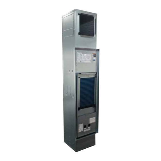
- Page 1 VSHPW Installation Manual Vertical Stack Unit ELA-13086 Water Source Heat Pump...
-
Page 2: Table Of Contents
Following the steps in the order Product Nomenclature ......31-32 presented should ensure proper installation. Warranty/Contact Information ....36 Due to Ice Air’s ongoing product development programs, the information in this document is subject to change without notice. -
Page 3: Overview/Application Note/Inspection
Overview Ice Air Vertical Stack Water Source Heat Pumps are quality units, which should only be installed by a trained professional. Please ensure all sections are read thoroughly before installing the unit. Application Note It is important for heating/cooling systems to be properly sized for each application in order to achieve desired temperature and humidity levels. -
Page 4: Physical Data
Return Air Min DB/WB 65/60 Return Air Max DB/WB 95/75 Entering Water Min*-Max 60-110 60-90 * Additional insulation may be required Due to Ice Air’s ongoing product development programs, the information in this document is subject to change without notice. -
Page 5: Performance Data
4.05 7.35 11.6 15.45 Compressor LRA 55.4 60.2 75.6 Fan Motor FLA 1.85 1.85 3.98 11.2 14.4 16.5 23.3 Fuse Size Due to Ice Air’s ongoing product development programs, the information in this document is subject to change without notice. -
Page 6: Before You Begin
Many carriers have a 15 day notice period from receipt of delivery delivering carrier’s Bill of Lading. to file any and all claims. Due to Ice Air’s ongoing product development programs, the information in this document is subject to change without notice. -
Page 7: Installation
SINGLE SUPPLY DOUBLE SUPPLY TRIPLE SUPPLY RETURN AIR FROM ROOM SUPPLY AIR TO ROOM SUPPLY RETURN DRAIN RISERS CASING LEFT RIGHT FRONT Due to Ice Air’s ongoing product development programs, the information in this document is subject to change without notice. -
Page 8: Riser Sizing And Insulation
– Install vents in piping loop as required to bleed the system of air accumulated during installation. Due to Ice Air’s ongoing product development programs, the information in this document is subject to change without notice. -
Page 9: Installing Modular Risers
SCALE 1 : 2.5 SCALE 1 : 2 33.000 10.500 6.500 10.000 2.164 3.000 4.000 4.470 5.000 ISOMETRIC FRONT VIEW TOP VIEW VIEW Due to Ice Air’s ongoing product development programs, the information in this document is subject to change without notice. -
Page 10: Storage
18 x 14 Recommended VSHPW36 18 x 10 18 x 10 18 x 14 Recommended STEEL DOUBLE DEFLECTION GRILLE OPPOSED BLADE DAMPER Due to Ice Air’s ongoing product development programs, the information in this document is subject to change without notice. -
Page 11: Casing Dimensions
21” 9” VSHPW-30/36K 22” 24” 25” 11” TOP VIEW FRONT OF BACK OF CASING CASING RIGHT VIEW REAR VIEW LEFT VIEW Due to Ice Air’s ongoing product development programs, the information in this document is subject to change without notice. -
Page 12: Installing The Casing
PRESSURE/TEMP TEST PLUG VALVE (OPTIONAL) BALL VALVES (BY OTHERS OR FACTORY MOUNTED ON RISERS) MOTORIZED VALVE (OPTIONAL) BRAIDED STAINLESS STEEL HOSES CHASSIS Due to Ice Air’s ongoing product development programs, the information in this document is subject to change without notice. -
Page 13: Optional Valve Accessories
The optional stainless-steel hoses comes with swivel connections for union of chassis and risers. Two hoses are provided per unit for connection of supply and return lines. Due to Ice Air’s ongoing product development programs, the information in this document is subject to change without notice. -
Page 14: Installing The Chassis
Poor fit up will affect unit air flow and performance. Install drywall using standard construction practices. Proper mechanical fasteners are required for installation. Due to Ice Air’s ongoing product development programs, the information in this document is subject to change without notice. -
Page 15: Installing The Access Panel
26.65 Frame Height (in) 62.44 Inner Panel Width (in) B 18.76 20.76 24.76 Inner Panel Height (in) 60.56 Depth (in) 1.75 Due to Ice Air’s ongoing product development programs, the information in this document is subject to change without notice. -
Page 16: Commercial Water Loop Applications
If an open type cooling tower is used continuously, chemical treatment and filtering will be necessary. Due to Ice Air’s ongoing product development programs, the information in this document is subject to change without notice. -
Page 17: Cleaning And Flushing
NOTE: DO NOT use “Stop Leak” or similar chemical agent in this system. Addition of chemicals of this type to the loop water will corrode the heat exchanger and inhibit unit performance. Due to Ice Air’s ongoing product development programs, the information in this document is subject to change without notice. -
Page 18: General Wiring Diagram
NOT IN USE RELAY3 = EVAP. BLOWER MOTOR RELAY(HI) LOW- FAN YEL/GRE ORNG RELAY4 = REVERSING VALVE RELAY ROOM TEMP PURPLE PURPLE Due to Ice Air’s ongoing product development programs, the information in this document is subject to change without notice. -
Page 19: System Start
Check for hot air delivery at registers. 6. If unit fails to operate properly, refer to troubleshooting section for possible solutions. Due to Ice Air’s ongoing product development programs, the information in this document is subject to change without notice. -
Page 20: System Check List
Pressure Differential (PSI) Flow Rate (GPM) Supply Voltage at Contactor (V) Transformer Low Side Volts (V) Compressor Amps (A) Motor Amps (A) Due to Ice Air’s ongoing product development programs, the information in this document is subject to change without notice. -
Page 21: Controls
• Time delay function: 3 minute delay for compressor at first power-on; (this can be using the dip switch; the default is delay post start-up) • System failure warning Due to Ice Air’s ongoing product development programs, the information in this document is subject to change without notice. - Page 22 Alarm ALARM Input 0/off; 24VAC/on setting is higher than the ambient temperature • Temperature Range: 51°F to 91°F Due to Ice Air’s ongoing product development programs, the information in this document is subject to change without notice.
- Page 23 Signal output (J3 = On) Medium High Medium High Medium High required by the space conditions Signal output(J3 = Off) Medium High Medium High Medium High Due to Ice Air’s ongoing product development programs, the information in this document is subject to change without notice.
- Page 24 Figure 7 will be shown on the main screen • Resume criterial: when the space temperature = 60°F, the unit go back to pervious working status Due to Ice Air’s ongoing product development programs, the information in this document is subject to change without notice.
- Page 25 to go back to the previous screen (see Figures 11, 12, 13) Due to Ice Air’s ongoing product development programs, the information in this document is subject to change without notice.
- Page 26 • If the settings for each day are different, then “Multiple” will be indicated; if the settings for several days is the same, the set time will be shown (see Figure 17) Due to Ice Air’s ongoing product development programs, the information in this document is subject to change without notice.
- Page 27 X or instead, the system will reminder the user to save or not save (see Figure 25) FIGURE 19 FIGURE 23 Due to Ice Air’s ongoing product development programs, the information in this document is subject to change without notice.
- Page 28 Habitat Wireless Thermostat Digital LCD Thermostat System compatible with other 3 party thermostats not shown here. For more information go to: www.ice-air.com/thermostats Due to Ice Air’s ongoing product development programs, the information in this document is subject to change without notice.
-
Page 29: Troubleshooting
Multiple power sources may be present. Failure to do so may cause property damage, personal injury or death. Due to Ice Air’s ongoing product development programs, the information in this document is subject to change without notice. -
Page 30: Preventative Maintenance
Preventive maintenance should only be performed by a certified restrictions. licensed technician. Consult a professional before creating a maintenance plan. Due to Ice Air’s ongoing product development programs, the information in this document is subject to change without notice. -
Page 31: Product Nomenclature
External P-Trap No P-Trap No Risers Unit Mounted Half Risers RISERS Unit Mounted Half Risers (Geothermal Units Only) Unit Mounted Full Risers Due to Ice Air’s ongoing product development programs, the information in this document is subject to change without notice. - Page 32 Custom MOTORIZED SHIPPING Shipped Loose VALVES OPTIONS 3-Way, 2-Position Motorized Valve NO None 3-Way, 2-Position Motorized Valve NC No Motorized Valve Due to Ice Air’s ongoing product development programs, the information in this document is subject to change without notice.
- Page 33 Notes or Technical Comments Due to Ice Air’s ongoing product development programs, the information in this document is subject to change without notice.
- Page 34 Notes or Technical Comments Due to Ice Air’s ongoing product development programs, the information in this document is subject to change without notice.
- Page 35 Notes or Technical Comments Due to Ice Air’s ongoing product development programs, the information in this document is subject to change without notice.
-
Page 36: Warranty/Contact Information
Vernon, New York 10553. Telephone 914-668-4700. 4) Damage due to failure to properly maintain unit. © 2022 by Ice Air, LLC ICE6135 01/22 Due to Ice Air’s ongoing product development programs, the information in this document is subject to change without notice.
Need help?
Do you have a question about the VSHPW and is the answer not in the manual?
Questions and answers