
Related Manuals for ATA ATR2700


Summary of Contents for ATA ATR2700
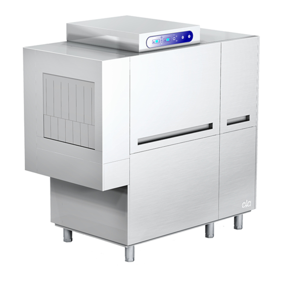
- Page 1 LAVASTOVIGLIE SERIE ATR LAVE-VAISSELLE SERIE ATR DISHWASHERS RANGE ATR GESCHIRRSPÜLMASCHINEN SERIE ATR LAVA VAJILLAS SERIE ATR...
- Page 2 MISURE D'INGOMBRO DIMENSIONS OVERALL DIMENSIONS ABMESSUNGEN DIMENCIONES...
- Page 3 165 235 ATR 100 ES 235 165 ATR 100 ED 1570 1570 1570 ATR2700ED 1570 ATR2700ES D = SCARICO Ø 40 mm, VIDANGE Ø 40 mm, DRAIN Ø 40 mm; ABFLUSS Ø 40 mm; DESAGÜE Ø 40 mm A,B = CARICAMENTO ACQUA CALDA ¾" GAS M; REMPLISSAGE EAU ¾" GAZ ; WATER INLET ¾" GAS, WASSERZUFLUSS ¾"...
- Page 4 CARATTERISTICHE TECNICHE / CARACTERISTIQUES TECHNIQUES / TECHNICAL FEATURES / ATR2700 TECHNISCHE DATEN / CARACTERISTICAS TECNICAS PRODUZIONE ORARIA (CESTI) / DÉBIT PANIERS-H / BASKETS PER HOUR / KÖRBE PRO STUNDE / 80 - 115 - 150 RENDIMIENTO HORARIO ALIMENTAZIONE ELETTRICA / ALIMENTATION ÉLECTRIQUE / ELECTRIC FEEDING / ELEKTRISCHER 230V3 –...
- Page 5 C B A 1870 ATR3200ES C B A C B A 1870 ATR3200ED C B A D = SCARICO Ø 40 mm, VIDANGE Ø 40 mm, DRAIN Ø 40 mm; ABFLUSS Ø 40 mm; DESAGÜE Ø 40 mm A,B,B’ = CARICAMENTO ACQUA CALDA ¾" GAS M; REMPLISSAGE EAU ¾" GAZ; WATER INLET ¾" GAS; WASSERZUFLUSS ¾"...
- Page 6 CARATTERISTICHE TECNICHE / CARACTERISTIQUES TECHNIQUES / TECHNICAL FEATURES / ATR3200 TECHNISCHE DATEN / CARACTERISTICAS TECNICAS PRODUZIONE ORARIA (CESTI) / DÉBIT PANIERS-H / BASKETS PER HOUR / KÖRBE PRO STUNDE / 90 - 135 - 180 RENDIMIENTO HORARIO ALIMENTAZIONE ELETTRICA / ALIMENTATION ÉLECTRIQUE / ELECTRIC FEEDING / ELEKTRISCHER 230V3 –...
- Page 7 C B A 2170 ATR3800ES C B A C B A 2170 ATR3800ED C B A D = SCARICO Ø 40 mm, VIDANGE Ø 40 mm, DRAIN Ø 40 mm; ABFLUSS Ø 40 mm; DESAGÜE Ø 40 mm A,B,B’ = CARICAMENTO ACQUA CALDA ¾" GAS M; REMPLISSAGE EAU ¾" GAZ ; WATER INLET ¾" GAS ; ZUFLUSS ¾"...
- Page 8 CARATTERISTICHE TECNICHE / CARACTERISTIQUES TECHNIQUES / TECHNICAL FEATURES / ATR3800 TECHNISCHE DATEN / CARACTERISTICAS TECNICAS PRODUZIONE ORARIA (CESTI) / DÉBIT PANIERS-H / BASKETS PER HOUR / KÖRBE PRO STUNDE / 110 - 160 - 210 RENDIMIENTO HORARIO ALIMENTAZIONE ELETTRICA / ALIMENTATION ÉLECTRIQUE / ELECTRIC FEEDING / ELEKTRISCHER 230V3 –...
- Page 9 C B A 2470 ATR4300ES C B A C B A 2470 ATR4300ED C B A D = SCARICO Ø 40 mm, VIDANGE Ø 40 mm, DRAIN Ø 40 mm; ABFLUSS Ø 40 mm; DESAGÜE Ø 40 mm A,B,B’ = CARICAMENTO ACQUA CALDA ¾" GAS M; REMPLISSAGE EAU ¾" GAZ; WATER INLET ¾" GAS; ZUFLUSS ¾"...
- Page 10 CARATTERISTICHE TECNICHE / CARACTERISTIQUES TECHNIQUES / TECHNICAL FEATURES / ATR4300 TECHNISCHE DATEN / CARACTERISTICAS TECNICAS PRODUZIONE ORARIA (CESTI) / DÉBIT PANIERS-H / BASKETS PER HOUR / KÖRBE PRO STUNDE / 140 - 190 - 240 RENDIMIENTO HORARIO ALIMENTAZIONE ELETTRICA / ALIMENTATION ÉLECTRIQUE / ELECTRIC FEEDING / ELEKTRISCHER 230V3 –...
- Page 11 C B A 3070 ATR4900ES C B A C B A 3070 ATR4900ED C B A D = SCARICO Ø 40 mm, VIDANGE Ø 40 mm, DRAIN Ø 40 mm; ABFLUSS Ø 40 mm; DESAGÜE Ø 40 mm A,B,B’,B’’ = CARICAMENTO ACQUA CALDA ¾" GAS M; REMPLISSAGE EAU ¾" GAZ; WATER INLET ¾" GAS; ZUFLUSS ¾"...
- Page 12 CARATTERISTICHE TECNICHE / CARACTERISTIQUES TECHNIQUES / TECHNICAL FEATURES / ATR4900 TECHNISCHE DATEN / CARACTERISTICAS TECNICAS PRODUZIONE ORARIA (CESTI) / DÉBIT PANIERS-H / BASKETS PER HOUR / KÖRBE PRO STUNDE / 160 - 215 - 270 RENDIMIENTO HORARIO ALIMENTAZIONE ELETTRICA / ALIMENTATION ÉLECTRIQUE / ELECTRIC FEEDING / ELEKTRISCHER 230V3 –...
- Page 13 ATR 240 ES 3370 B' ' C B A C B A ATR 240 ED B' ' B' ' B' ' 235 165 3370 C B A C B A C B A 822.6 317.1 3370 ATR5400ES C B A C B A 817.5 317.5...
- Page 14 CARATTERISTICHE TECNICHE / CARACTERISTIQUES TECHNIQUES / TECHNICAL FEATURES / ATR5400 TECHNISCHE DATEN / CARACTERISTICAS TECNICAS PRODUZIONE ORARIA (CESTI) / DÉBIT PANIERS-H / BASKETS PER HOUR / KÖRBE PRO STUNDE / 190 - 245 - 300 RENDIMIENTO HORARIO ALIMENTAZIONE ELETTRICA / ALIMENTATION ÉLECTRIQUE / ELECTRIC FEEDING / ELEKTRISCHER 230V3 –...
- Page 15 LAVASTOVIGLIE A CESTO TRASCINATO INSTALLAZIONE,USO E MANUTENZIONE...
-
Page 16: Installazione
AVVERTENZE La macchina è stata progettata per la pulizia di stoviglie, bicchieri, posate e vassoi in cucina. Leggere attentamente le istruzioni prima dell’installazione ed uso della lavastoviglie. L’installazione deve essere effettuata da personale qualificato secondo le istruzioni del costruttore riportate nell’apposito manuale. -
Page 17: Posizionamento Della Macchina
Incollare la guarnizione (2) Collegare i tubi di scarico (8) Unire i moduli (3) Infilare le Effettuare il collegamento protezioni(4) equipotenziale (7) Staffa connettori Bloccare la parte Bloccare la parte inferiore con le viti inferiore con le viti (5) Togliere i pannelli frontali (1) Effettuare la connessione elettrica (6) POSIZIONAMENTO DELLA MACCHINA Collocare la lavastoviglie nella posizione prescelta ed effettuare il livellamento in modo che la... - Page 18 acqua fredda. In caso contrario, la lavastoviglie necessita soltanto dell'alimentazione con acqua fredda. Prima di procedere all'allacciamento verificare le seguenti condizioni: la pressione di alimentazione, misurata a valvola aperta, dovrà variare tra 2 e 4 bar. In fase di risciacquo attivo, se la pressione dell’alimentazione dell’acqua è...
- Page 19 MONTAGGIO PIANI DI LAVORO A completamento della lavastoviglie sono disponibili i piani di lavoro semplici o con lavello e doccione o con il lavello, doccione e sbarazzo. Assemblaggio del piano: fissare le gambe di sostegno alle viti situate inferiormente al Piano di lavoro piano di lavoro;...
-
Page 20: Allacciamenti Elettrici
Per montare il paraspruzzi o la cappa di aspirazione delle fumane, appoggiare il componente stesso alla parete laterale con il bordo Cappa aggiuntiva inferiore all’interno della macchina, infilare nuovamente le protezioni Bordi che erano state sfilate in precedenza e fissare il tutto con le viti; alla intern fine reinserire il pannello laterale inferiore. - Page 21 I(A) max assorbita Potenza (kW) MODELLO 400V ~ 3F+N installata 230V ~ 3F (50Hz) (50Hz) 27,3 39,5 68,6 ATR2700 33,3 48,1 83,7 36,3 52,5 91,2 27,1 39,2 68,1 ATR3200 33,1 47,8 83,2 36,1 52,2 90,7 28,3 40,9 71,1 ATR3800 34,3...
- Page 22 DOTAZIONI MODELLO CODICE DESCRIZIONE QUANTITÀ ATR2700 907500 CESTO PIATTI 18 SPAZI ATR3200 907501 CESTO PIATTI 16 SPAZI ATR3800 907503 CESTO POSATE 16 SPAZI ATR3800A 911516 CESTO BICCHIERI 16 SPAZI 907500 CESTO PIATTI 18 SPAZI ATR4300 ATR4300A 907501 CESTO PIATTI 16 SPAZI...
- Page 23 In figura vengono riportati i tre diversi pannelli comandi in base al numero totale delle vasche di lavaggio e prelavaggio presenti nel modello ed in particolare: Pannello comandi 1 vasca lavaggio : ATR2700; Pannello comandi 2 vasche lavaggio : ATR3200, ATR3800 e ATR4300;...
- Page 24 A questo punto la macchina procede automaticamente a portare il livello dell’acqua di tutte le vasche presenti al punto prestabilito. Tale operazione è indicata dall’accensione del led (6) che si spegnerà alla fine della fase di caricamento. Si tenga presente che, nel digit (14) viene indicata la temperatura relativa alla vasca stabilita tramite i pulsanti selezione (A,B,C) dove (A) è...
-
Page 25: Sistemi Di Sicurezza
Il lavaggio ha inizio solo quando a seguito dell’introduzione di un cesto viene azionata la leva dell’economizzatore di lavaggio montata di serie su tutti i modelli. I cesti devono essere caricati convenientemente in base alla loro destinazione d’uso. Si consiglia di non sovraccaricarli e di non sovrapporre le stoviglie in modo da impedire una corretta azione dei getti di lavaggio. -
Page 26: Manutenzione
In caso di apertura di una delle porte di ispezione si ha il blocco automatico di tutte le funzioni della lavastoviglie ad eccezione del caricamento o del riscaldamento dell’acqua. Un limitatore di coppia montato sul traino blocca il movimento dello stesso in caso di impedimenti accidentali al regolare avanzamento dei cesti. - Page 27 Si controllino accuratamente i fori dei tubi di lavaggio provvedendo alla loro pulizia se risultassero ostruiti. Pulire accuratamente i filtri dopo averli asportati dalla loro sede. Si fa notare che è sempre buona norma chiudere il rubinetto dell’alimentazione dell’acqua quando la lavastoviglie non è...
- Page 28 Informazioni per gli apparecchi elettrici ed elettronici usati nei paesi UE Le apparecchiature che riportano il simbolo , secondo le direttive UE non possono venire smaltiti insieme con i normali rifiuti domestici. Per l’eliminazione di una apparecchiatura dismessa, servirsi dei sistemi di raccolta differenziata messi a disposizione nei singoli paesi di utilizzo, oppure contattare il rivenditore nel caso si acquisti un prodotto equivalente.
-
Page 29: Installation, Use And Maintenance
RACK-CONVEYOR DISHWASHER INSTALLATION, USE AND MAINTENANCE... -
Page 30: Installation
WARNING The appliance is to be used for washing dishes, glasses, cutlery and trays. 1) Read the instructions carefully before installation, use and maintenance of the appliance. 2) The installation has to be performed by qualified personnel following the manufacturer's instructions given in the provided manual. -
Page 31: Positioning Of The Appliance
Stick the seal (2) Connect the drain hoses (8) Place the units together (3) Insert the edge Connect the appliance to the covers(4) equipotential system (7) Connector bracket Fix the lower part of the units together with screws (5) Remove the frontal panels (1) Connect the cables (6) POSITIONING OF THE APPLIANCE Place the appliance in the position you have chosen and level it by lowering or raising the adjustable... - Page 32 On the contrary, if the dishwasher is pre-set for being connected to cold water, the appliance requires the cold water filling only. Before proceeding with the water connection, check the following conditions: The water supply pressure, measured with open valve, has to vary between 2 and 4 bars. If during the rinsing cycle the water supply pressure is lower than 2 bars, install a booster pump or an autoclave granting a pressure of at least 2,5 bars;...
- Page 33 TABLING INSTALLATION A certain number of tables are available as accessories: simple tables; tables with sink and shower; tables with sink, shower and scraping hole. Assembling tables: Fix the supporting legs to the screws placed below the working Working surface surface.
-
Page 34: Electric Connection
In order to install the splash guard or the steam exhauster, lean the unit to the side panel and place its lower edge into the appliance. Then Additional exhauster insert again the removed edge covers and fix them with some screws; Internal put the lower side panel back into its place. - Page 35 I(A) max MODEL Power (kW) 400V ~ 3F+N 230V ~ 3F (50Hz) (50Hz) 27,3 39,5 68,6 ATR2700 33,3 48,1 83,7 36,3 52,5 91,2 27,1 39,2 68,1 ATR3200 33,1 47,8 83,2 36,1 52,2 90,7 28,3 40,9 71,1 ATR3800 34,3 49,6 86,2...
- Page 36 EQUIPMENT MODEL REFERENCE DESCRIPTION QUANTITY ATR2700 907500 RACK 18 PLATES ATR3200 907501 RACK 16 PLATES ATR3800 907503 RACK FOR 16 CUTLERY BASKETS ATR3800A 911516 RACK FOR 16 GLASSES 907500 RACK 18 PLATES ATR4300 907501 RACK 16 PLATES ATR4300A 907503 RACK FOR 16 CUTLERY BASKETS...
- Page 37 In the picture they are shown the three control panels, according to the number of washing and pre- washing tanks of the appliance and in particular: 6) Control panel 1 washing tank ATR2700; 7) Control panel 2 washing tanks ATR3200, ATR3800 and ATR4300;...
-
Page 38: Warning Message
The appliance automatically fills water into all the tanks up to the set level; this operation is shown by the lighting of the lamp (6), which will switch off at the end of the water filling. The digit (14) shows the water temperature in the tank chosen by means of the tank selection buttons (A, B, C): (A) represents the washing tank 1;... -
Page 39: Rinsing Cycle
Racks should be filled according to the use they are suitable for. Do not overfill the racks and do not place one item on the other; otherwise washing water can not clean the kitchenware properly. Moreover, even if racks can be filled and dragged according to any coupling position, it is recommended to place dishes with their concave part forward. -
Page 40: Maintenance
A torque-limiting device stops the conveyor in case of chance obstacles to the right movement of the racks. A limit switch stops the washing cycle and the conveyor if a rack is at the end of the exit table; at the same time a sound alarm starts ringing until the rack is removed. -
Page 41: Periodic Maintenance
Remove the filters and clean them carefully. It is highly recommended to turn off the tap of filling water when the appliance is not working. STAINLESS STEEL PARTS CLEANING Clean all the stainless steel parts accurately by using soaped water or common degreasing products. Do not use abrasive powders or iron wool. - Page 42 Information for electrical and electronic devices used in EU countries According to EU directives, devices marked with the following symbol may not be disposed of together with normal household waste. To dispose of your used device, please use the locally available differentiated collection system or consult your retailer when you buy an equivalent product.
Need help?
Do you have a question about the ATR2700 and is the answer not in the manual?
Questions and answers
warning coming
A warning message for the ATA ATR2700 indicates an anomaly in the pump amperometric protections, safety thermostats of boilers, or geared motor. When this occurs, the red lamp (8) lights up, an acoustic warning sounds, and the appliance stops until it is reset by qualified personnel. If the boiler digit (15) or the tank digit (14) displays the letter “E,” it means the thermometer probe is disconnected or faulty. In this case, the probe should be checked for proper connection or replaced if necessary.
This answer is automatically generated
showing warning
The warning for the ATA ATR2700 indicates various issues:
1. If the appliance stops abnormally, the warning LED (8) switches on. If this happens repeatedly, a specialized technician should be called.
2. If the safety thermostats in the boilers detect a temperature higher than allowed, the anomaly warning lamp (8) lights up, and the heating elements stop working. To reset the appliance, the safety thermostat behind the frontal panel of the rinsing module must be manually operated.
3. The anomaly warning lamp also lights up in case of issues with the inverter in the electric box.
4. All electrical components are protected by fuses that cut power in case of overcurrent.
These warnings help indicate potential electrical or thermal issues that need to be addressed.
This answer is automatically generated