
Related Manuals for ATO EM15-SP Series

Summary of Contents for ATO EM15-SP Series
- Page 1 User Manual EM15-SP Series VFD ATO Inc Address: 23555 GOLDEN SPRINGS DR. K-1, DIAMOND BAR, USA Phone: 1800-585-1519 Zip code: 91765 Website : https://www.ato.com/...
- Page 2 EM15-SP User Manual Preface Preface Thank you for purchasing the solar drive developed by our company. Features: ⚫ MPPT algorithm of fast tracking of maximum power point of PV cells, efficiency >99%. ⚫ Solar battery working point voltage can be manually or automatically MPPT tracking. ⚫...
-
Page 3: Table Of Contents
1.1 Safety Information ............................1 2. Product Information ..............................3 2.1 Designation Rules ............................3 2.2 EM15-SP series .............................. 3 2.3 Product appearance and installation dimension ..................... 4 2.3.1 Product appearance ..........................4 2.3.2 EM15-SP VFD appearance and installing dimension(mm) ..............4 2.3.3 Appearance and installation dimension of external keypad (keypad tray) .......... -
Page 4: Safety Information And Precautions
EM15-SP User Manual 1. Safety Information and Precautions 1. Safety Information and Precautions In this manual, the notices are graded based on the degree of danger: Danger: Indicates that failure to comply with the notice will result in severe personal injury or even death. Warning: Indicates that failure to comply with the notice will result in personal injury or property damage. - Page 5 1. Safety Information and Precautions EM15-SP User Manual Warning: ⚫ When two solar inverters are laid in the same cabinet, arrange the installation positions properly to ensure the enough cooling effect. Do not drop wire residue or screw into the solar drive. Failure to comply will result in damage to the solar ⚫...
-
Page 6: Product Information
1: DC 310 / AC 1PH 220V In AC 3PH 220V Output 3: DC 540V/AC 3PH 380V In AC 3PH 380V Output Diagram 2-1 Designation rules 2.2 EM15-SP series Table 2-1EM15-SP Models and technical datas EM15-SP1[S] Description DC input (+, -) Rated power/KW 0.75... -
Page 7: Product Appearance And Installation Dimension
2. Product Information EM15-SP User Manual 2.3 Product appearance and installation dimension 2.3.1 Product appearance Diagram 2-2 Product appearance (With potentiometer) 2.3.2 EM15-SP variabe frequency drive appearance and installing dimension(mm) Diagram 2-3 Appearance and installation dimension of EM15 series (Plastic housing structure) Appearance and installing dimension ( Unit: mm ) Matching inverter Voltege... -
Page 8: Appearance And Installation Dimension Of External Keypad (Keypad Tray)
EM15-SP User Manual 2. Product Information Diagram 2-4 Appearance and installation dimension of EM15 series (Metal housing structure) Appearance and installing dimension ( Unit: mm ) Matching inverter Voltege Power Range 3PH 220V 15~18.5kW Φ7 3PH 380V 30~37kW 3PH 220V 22kW Φ10 3PH 380V... -
Page 9: Installation Of Variable Frequency Drive
3. Installation of variable frequency drive EM15-SP User Manual 3.Installation of variable frequency drive 3.1 Installation environment 1. The place with indoor vents or ventilation devices. 2. The environment temperature shall be -10℃~40℃. If the temperature is over 40℃but less than 50℃, better to take down the cover of variable frequency drive or open the front door of cabinet to facilitate heat dissipation. -
Page 10: Sketch And Description Of Main Circuit Terminals
3. Installation of variable frequency drive EM15-SP User Manual 3.3 Sketch and Description of Main Circuit Terminals 3.3.1 Function and description of Main Circuit Terminals Single phase 220V output:EM15-SP1S-d75 ~ EM15-SP1S-011 Three phase 220V output:EM15-SP1-d75~EM15-SP1-011 Three phase 380V output:EM15-SP3-d75~EM15-SP3-022 Three phase 380V output:EM15-SP3-030~EM15-SP3-090 Three phase 380V output:EM15-SP3-110~EM15-SP3-400 Terminal symbol Function description... -
Page 11: Control Circuit And Main Circuit Terminals Description
3. Installation of variable frequency drive EM15-SP User Manual 3.4 Control Circuit and Main Circuit Terminals Description 3.4.1 Control Circuit and Main Circuit Wiring Diagram3-2 EM15-SP control circuit and main circuit wiring... -
Page 12: Control Circuit Terminal Layout
3. Installation of variable frequency drive EM15-SP User Manual 3.4.2 Control Circuit Terminal Layout Diagram3-3 EM15-SP control circuit terminal sketch diagram 3.4.3 Description of control circuit terminals Terminal Terminal Type Terminal function description Symbol Name Provide +10V power supply to external unit. Maximum output External current:10Ma +10V-GND... -
Page 13: Collection Diagram For Different Motor
3. Installation of variable frequency drive EM15-SP User Manual Terminal Terminal Type Terminal function description Symbol Name specifications is the same as DO. TA1-TB1 NC terminal TA2-TB2 Contact driving capacity: 250 VAC, 3 A, COSø = 0.4 Relay output TA1-TC1 DC 30 V, 1 A NO terminal TA2-TC2... -
Page 14: The Wiring Of Water-Level Automatic Control
3. Installation of variable frequency drive EM15-SP User Manual Photovoltaic cell EM15-SP Water Tank + - U V W Water Pipe C o n t r o l Te r m i n a l Pump Diagram of 3phsae inverter connection method (PV Input) Diagram3-5 3.5. - Page 15 3. Installation of variable frequency drive EM15-SP User Manual “COM” as well as controller automatically stop the pump to prevent anhydrous idling. The wiring for floater water-level switch mounted on a side The floater water-level switch mounted on a side is the normally open contact to output and its common wire is connected to the terminal COM of EM15-SP inverter.
-
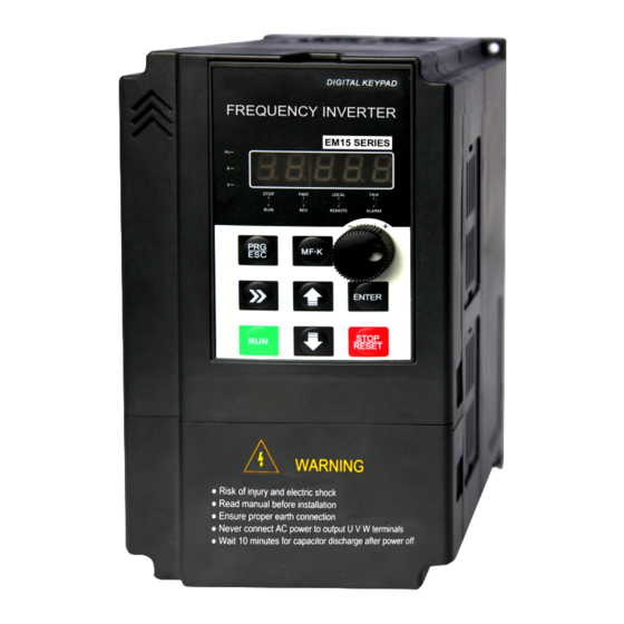
Page 16: Operation And Display
EM15-SP User Manual 4. Operation and Display 4 Operation and display 4.1 Instruction of operation and display Diagram 4-1 Operating panel Name Function The 5-digit LED display is able to display the set frequency, output frequency, monitoring LED display area data and fault codes. -
Page 17: Function Code Table
4. Operation and Display EM15-SP User Manual 4.2 Function Code Table If FP-00 set to a non-zero number, parameter protection is enabled. You must write in correct user password to enter the menu. To cancel the password protection function, enter with password and set FP-00 to 0。 The parameter menu under the user-defined parameter mode can directly enter without password. - Page 18 EM15-SP User Manual 4. Operation and Display Code Name Description Default 0: No binding 1: Frequency source by digital setting 2: AI1 3: AI2 4: Keypad potentiometer 9: Communication setting Ten's digit:: Binding terminal command to frequency source. Hundred's digit: Binding communication command to frequency source.
- Page 19 4. Operation and Display EM15-SP User Manual Code Name Description Default F9: Fault and Protection parameters F9-09 Fault auto reset times 0~20 Relay action selection during 0: Not act F9-10 fault auto reset 1: Act Time interval of fault auto reset 0.1s~100.0s F9-11 5.0s Unit's digit: Input phase loss protection...
- Page 20 EM15-SP User Manual 4. Operation and Display Code Name Description Default FE-05 CVT Integral gain1 0.0%-999.9% 100.0% FE-06 Reserved FE-07 Reserved FE-08 Reserved FE-09 Reserved FE-10 Mppt search upper limit voltage 0-1000.0V 750.0V FE-11 Mppt search lower limit voltage 0-1000.0V 300.0V FE-12 MPPT search gain...
- Page 21 4. Operation and Display EM15-SP User Manual Code Name Description Default FP: Parameters for User password 0 ~ 65535 FP-00 User password 00000 0: No operation 1: Restore default settings except motor parameters and accumulation record. FP-01 Restore default settings 02: Clear records 04: Back up present user parameters 501: Restore user backup parameters...
-
Page 22: Description Of Function Codes
EM15-SP User Manual 5. Description of Function Code 5. Description of Function Codes F0: Basic Function Parameters Group 1: G type(Constant torque load models ) Model F0-00 G/P type selection 2: P type(Fan, water pump load models ) dependent This parameter is used to display the delivered model and cannot be modified. 1: Applicable to constant torque general load with rated parameters specified. - Page 23 5. Description of Function Code EM15-SP User Manual AI2: 0V~10 V voltage input or 0mA ~ 20mA current input, determined by jumper JP3 on the control card; The corresponding relationship curve between the input voltage of AI1, AI2 and the target frequency can be user-defined.
- Page 24 EM15-SP User Manual 5. Description of Function Code 0.00s~650.00s(F0-19=2) Model F0-17 Acceleration time 1 0.0s~6500.0s(F0-19=1) dependent 0s~65000s(F0-19=0) 0.00s~650.00s(F0-19=2) Model F0-18 Deceleration time 1 0.0s~6500.0s(F0-19=1) dependent 0s~65000s(F0-19=0) Acceleration time indicates the time required by the variable frequency drive to accelerate from 0 Hz to "Acceleration / Deceleration base frequency"(F0-25 ) that is, t1 in Diagram 6-1.
-
Page 25: F1 Motor Parameter
5. Description of Function Code EM15-SP User Manual The acceleration/deceleration time indicates the time for the variable frequency drive to increase from 0 Hz to the frequency set in F0-25,figure 6-1 is the acceleration/deceleration time diagram. If this parameter is set to 1, the acceleration/deceleration time is related to the set frequency. If the set frequency changes frequently, the motor's acceleration/deceleration also changes. -
Page 26: F4 Input Terminals
EM15-SP User Manual 5. Description of Function Code F4 Input Terminals The EM15 provides six digital input (DI) terminals (HDI can be used for high-speed pulse input) and two analog input (AI) terminals. The optional extension card provides another six DI terminals (DI7 to DI12) and one AI terminal (AI3). -
Page 27: F9 Faults And Protection Parameters
5. Description of Function Code EM15-SP User Manual the value of this parameter to stabilize the detected analog input. However, increase of the AI filter time will slow down the response of analog detection. Set this parameter properly based on actual conditions. In different applications, 100% of analog input corresponds to different nominal values. -
Page 28: Fe Solar Water Pump Control Parameters
EM15-SP User Manual 5. Description of Function Code It is used to determine whether to perform output phase loss protection. 0 ~ 99 F9-14 Fault type It is used to record the types of the most recent three faults of the variable frequency drive. 0 indicates no fault. F9-37 It displays the frequency when the latest fault occurs. - Page 29 5. Description of Function Code EM15-SP User Manual PE-01 PE-10~PE-13 PE-04~PE-08 MPPT Controller PE-02 Diagram 5-3 Photovoltaic water pump control schematic FE-04 CVT proportional gain 1 0.0% - 999.9% 100.0% FE-05 CVT Integral gain1 0.0% - 999.9% 100.0% It is CVT controller’s PI parameters,it should be switchover in two groups according to solar cells Vpn voltage , switchover point is FE-08V;...
- Page 30 EM15-SP User Manual 5. Description of Function Code detection time of full-water FE-33 0 - 30000sec 10sec protection exit time of full-water FE-34 0 - 30000sec 60sec protection analog sensor damaged FE-35 0 - 100.0% 0.0% Thresholds FE-31 is for Full-water detection mode. If set to 0, set any terminals(default DI4/DI5)function code to 51/52,two terminals enabled in same time could activate Full-water protection and two terminals disabled in same time could activate exit Full-water protection.
-
Page 31: Fp User Password Parameters
5. Description of Function Code EM15-SP User Manual FP User password parameters 0 ~ 65535 User password FP-00 If it is set to any non-zero number, the password protection function is enabled. After a password has been set and taken effect, you must enter the correct password in order to enter the menu. If the entered password is incorrect you cannot view or modify parameters. -
Page 32: Fault Diagnosis And Solution
EM15-SP User Manual 6. Fault Diagnosis and solution 6. Fault Diagnosis and Solution 6.1 Fault Alarm and Countermeasures EM15-SP VFD has 35 types of warning information and protection function. In case of abnormal fault, the protection function will be invoked, the inverter will stop output, and the faulty relay contact of the inverter will start, and the fault code will be displayed on the display panel of the inverter. - Page 33 6. Fault Diagnosis and solution EM15-SP User Manual Fault Code Err09 Fault Type Low voltage 1: Instantaneous power failure occurs on the input 1: Reset the fault. power supply. 2: The frequency inverter's input voltage is not within 2: Adjust the voltage to normal range. the allowable range.
-
Page 34: Appendix I. Modbus Communication Protocol
Appendix I. Modbus communication protocol ATO-EM15-SP VFD provides RS485 communication interface, and adopts MODBUS communication protocol. User can carry out centralized monitoring through PC/PLC to get operating requirements. And user can set the running command, modify or read the function codes, the working state or fault information of variable frequency drive by Modbus communication protocol. - Page 35 6. Fault Diagnosis and solution EM15-SP User Manual information provided by master, slave needs not feedback a response to master machine. Communication data structure Modbus protocol communication data format of EM15 series inverter is shown as following. The inverter only support the reading and writing of Word type parameters, the corresponding reading operation command is “0x03”, the writing operation command is “0x06”.
- Page 36 1Byte 2Byte >3.5Byte 1Byte 1Byte Slave reads and Target Read the Free response error correction and station command Error type Free (Start frame) frame address (0x83) L……H Calculate CRC Error types: correction 01-Command code error 02-Address error 1Byte 2Byte >3.5Byte 1Byte 1Byte 03-Data error...
- Page 37 6. Fault Diagnosis and solution EM15-SP User Manual When the CRC is appended to the message, the low-order byte is appended first, followed by the high-order byte. unsigned int crc_chk_value(unsigned char *data_value,unsigned char length unsigned int crc_value=0xFFFF; int i; while(length--) crc_value^=*data_value++;...
- Page 38 1006H Output torque 1016H Voltage before AI1correction 1007H Running speed 1017H Voltage before AI2correction 1008H DI input terminal 1018H Voltage before AI3correction 1009H DO output terminal 1019H Linear speed 100AH AI1 voltage 101AH Present power-on time 100BH AI2 voltage 101BH Present running time 100CH AI3 voltage...
- Page 39 6. Fault Diagnosis and solution EM15-SP User Manual Analog output AO1 control: (write in only) Command word address Command function 2002H 0~7FFF indicates 0%~100% Analog output AO2 control: (write in only) Command word address Command function 2003H 0~7FFF indicates 0%~100% Pulse output control: (write in only) Command word address Command function...
- Page 40 Code Parameter Name Setting Range Default 2: Odd Parity check, data format<8,O,1> 3: No check, data format <8,N,1> The host computer and variable frequency drive setup data format must be consistent, otherwise, communication is impossible. Code Parameter Name Setting Range Default Fd-02 0~247 (0: Broadcast address)
Need help?
Do you have a question about the EM15-SP Series and is the answer not in the manual?
Questions and answers