Table of Contents
Advertisement
Quick Links
Date Created: 09/05/2017
Title: Road Kit Option Fitment
SAFETY!
Before attempting to make any adjustments or carry out maintenance on the mower, review
the hazard identification table (section 3a of your Operator Manual) and take all necessary precautions.
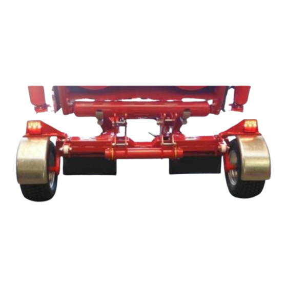
Mudguard Mounts
SPARE PARTS
INSTRUCTIONS # 49
Product: Snake
Collect the following parts:
2 x Mudguard Mounts
(410-000-247)
2 x Rolled Mudguards
(410-000-245)
2 x Mudguard Clamp Plated
(410-000-246)
8 x M8 x 25 Bolts
8 x M8 Nyloc Nuts
Position the Rolled Mudguards
(410-000-245) as shown.
Insert the M8 x 25 Bolts through the
Mudguard Mounts (410-000-247) and
the Rolled Mudguards
(410-000-245)
Note:
The orientation of the Guards must be
as shown to make a Left and Right-
Hand Assembly.
Position the Mudguard Clamp Plate
(410-000-246) as shown.
Secure with M8 Nyloc nuts.
Fully tighten.
Repeat for the second Mudguard.
1
Advertisement
Table of Contents

Related Manuals for Trimax Snake

Summary of Contents for Trimax Snake
- Page 1 SPARE PARTS INSTRUCTIONS # 49 Date Created: 09/05/2017 Product: Snake Title: Road Kit Option Fitment SAFETY! Before attempting to make any adjustments or carry out maintenance on the mower, review the hazard identification table (section 3a of your Operator Manual) and take all necessary precautions.
- Page 2 Tighten to secure. LED Tail Light Wiring Feed the LED Tail Light Wiring through here through the holes shown. Position the Right-Hand Mudguard Assembly over the Right-Hand Tyre on the Snake Chassis as shown. Note: See next picture for Bolt Setup detail.
- Page 3 Spring Washers and Plain Fully tighten. Nuts from this side Repeat the above fitment to secure the Left-Hand Mudguard Assembly to the Snake Chassis. The parts used are IDENTICAL. Loom through Plug the Trailer Loom Ext. Cable here 3.2m (421-000-055) into the Right-Hand LED Light Cable.
- Page 4 Insert the Loom through the Rear Outrigger Mount Plate as shown. Note: This is UNDERNEATH the Chassis Rear Axle. Loom through here Insert the Loom through the Front and Rear Lift Frame Plates. Note: This is UNDERNEATH the Left and Right-Hand Hydraulic Rams.
- Page 5 Mark out the two positions shown on the Right-Hand Chassis Rail. These will need to be drilled to rivet Mark here the P-Clips in place to secure the Loom. 100mm / 4” 100mm / 4” Each position is central between the TOP and Bottom of the Chassis Rail.
- Page 6 Pull all excess Loom through towards the FRONT of the Chassis. Using two Cable Ties (210-900-010) secure the Looms to the REAR of the 4-Way Gearbox Mount as shown. Trim the tails off the Cable Ties. Note: This is UNDERNEATH the Chassis 4-Way Gearbox.
- Page 7 Align the arrows and attach the Trailer Plug Inc. 1m Cable (421-000-053) to the Y-connector (421-000-054) Trailer Plug Use 1.3m/ 4’ 1/4" of Spiral Wrap Rope and Hose Guide (450-900-014) secure the Looms and Main Hydraulic Hose together. Start the Spiral Wrap from just under the 4-Way Gearbox Mount Plate (418-000-484) to the Y-Connector (421-000-05)
Need help?
Do you have a question about the Snake and is the answer not in the manual?
Questions and answers