
Summary of Contents for Lightstar KDX-300
- Page 1 KDX-300 INSTRUCTION MANUAL (FULL VERSION) SIZE Compact size Max. value Consumed Energy RS-485 Clear Large (96x96mm) automatically saved Generated Energy Communication LCD display...
-
Page 2: Table Of Contents
Contents Page.1 1. General Introduction 1.1 General Page.2 1.2 Dimensions Page.2 1.3 Specification Page.3 1.4 Function and accuracy Page.3 2. Connection method 2.1 Power, PT, CT connection Page.4 3. Configuration Page.5 3.1 LED Page.5 3.2 Key Page.5 3.3 LCD Page.5 3.4 Terminals 4. -
Page 3: General Introduction
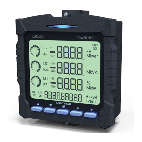
Prior to cabling, be sure to check the designed aux power and connection diagram. 1.1 General Function KDX-300 can measure/display electric data of the system and transmit data via RS-485 communication. This can measure voltage, current, power, energy, power factor, frequency, phase angle, harmonics. Features Remote monitoring can be supported by RS-485 communication. -
Page 4: Connection Method
Chapter_1. General Introduction Page.3 1.3 Specification Type Panel mounted Operating power AC90V ~ 260V(50/60Hz), DC 110V Operating temperature 0~55℃ Operating humidity 20~80% Operating condition Less than ‘2,000m above sea level’ without vibrations or shocks Burst immunity test Burst, Level 4 (IEC 61000-4-4) Surge impulse test Voltage(1.2㎲/50㎲, 5kV), Current(8㎲/20㎲)(IEC 60255-5) Electrostatic discharge immunity test... -
Page 5: Power, Pt, Ct Connection Page.4
Chapter_2. Connection method Page.4 2.1 Power, PT, CT connection (without PT) (without PT) -
Page 6: Configuration
Chapter_3. Configuration Page.5 Panel Power Meter KDX-300 PT Input AC 40 ~ 500V CT Input 0.1 ~6A Source AC 90~260V, DC 110V 3.1 LED This device is equipped with 5 LED on the front top, which help to recognize power consumption easily. -
Page 7: Setting Method
Chapter_4. Setting method Page.6 4.1 Setting Setting procedure ● connection method > PT ratio > CT ratio > Communication ID & Adress > Max value reset -Energy reset > All setting reset > backlight > Firmware information > Frequency Button function ●... -
Page 8: Default Value Page.7
Chapter_4. Setting method Page.7 4.2 Default value Default value Connection method : 3P4W PT ratio : 190:190 (Direct) CT ratio : Backlight : Automatically off after 60 seconds on RS-485 communistion : 255 (ID), 9600bps Frequency : 60Hz 4.3 Conversion table for decimal point and unit - Decimal point and unit for Voltage Primary voltage 110V... - Page 9 Chapter_4. Setting method Page.8 3Φ3W CT/PT Ratio 3.30k 6.60k 7.20k 11.0k 11.4k 22.0k 22.9k 66.0k 154k .000kW .00kW .0kW .00kW .00MW .0kW .00MW .00MW 1000 1200 1250 1300 1400 1500 1600 .00MW 1700 1750 1800 2000 .0MW 2500 3000 3200 3500 3600 4000...
- Page 10 Chapter_4. Setting method Page.9 3Φ4W CT/PT Ratio 11.4k 22.9k .000kW .0kW - Decimal point and Unit .000kW -> 3rd decimal point, Unit: kW .00kW .00kW -> 2nd decimal point, Unit: kW .0kW -> 1st decimal point, Unit: kW -> Without decimal point, Unit: kW .00MW ->...
-
Page 11: Mode Description
Chapter_5. Mode description Page.10 5.1 Display item per page Basic mode Functions Display Item Display Item page page Reverse reactive energy Phase voltage / Frequency R phase voltage, current, active power Line-to-line voltage / Frequency S phase voltage, current, active power Current loadrate / Zero phase current T phase voltage, current, active power Phase power factor / Total power factor... - Page 12 Chapter_5. Mode description Page.11 5.2 Display mode Display power metering values and status PAGE.1 Phase Voltage and Frequency Values referring PT ratio * PT ratio can be adjusted in setting mode. * Decimal point and unit can be varied by PT ratio. (Refer to decimal point/ unit table) PAGE.2 Line to line Voltage and Frequency...
- Page 13 Chapter_5. Mode description Page.12 PAGE.6 Phase reactive power and total reactive power ※Decimal point and unit can be varied by CT/PT ratio ※Lead : lag : PAGE.7 Phase apparent power and total apparent power ※Decimal point and unit can be varied by CT/PT ratio PAGE.8 +Normal active energy Displayed max.
- Page 14 Chapter_5. Mode description Page.13 PAGE.12 R phase information Voltage / current / circular graph / active power for R phase PAGE.13 S phase information Voltage / current / circular graph / active power for S phase PAGE.14 T phase information Voltage / current / circular graph / active power for T phase PAGE.15 Phase voltage Max.value...
- Page 15 Chapter_5. Mode description Page.14 PAGE.17 Phase current Max.value ※Max.value can be reset in setting mode (Page 5) PAGE.18 Active power Max.value ※Max.value can be reset in setting mode (Page 5) PAGE.19 Voltage phase angle R phase angle S phase angle T phase angle PAGE.20 Voltage line to line angle...
- Page 16 Chapter_5. Mode description Page.15 5.3 Setting mode In order to set and check the KDX-3 Series’s operating condition, hold the third key(●) for 2 seconds and switch to setting mode. In settings mode, use the ◀, ▶ keys to check information and press the ●key to set and complete. You can easily check your current location using page number.
-
Page 17: Page.10
Chapter_5. Mode description Page.16 Reset - Active energy, reactive energy PAGE.6 ① In setting mode, move to energy reset page. ② Using ● key, setting to be ready. ③ Using ▲,▼ key, choose ‘YES’ or ‘NO’. ④ Pushing ● key, after choose ‘YES’ , Wh and varh to be reset and move to first page. - Page 18 Chapter_5. Mode description Page.17 5.4 Harmonic mode Harmonics can be measured to 32nd order and transmitted by communication. But on device, it can be displayed to 15th order only . Press ▼ + ▲ at the same time you may enter to harmonic mode, And press ● key, you may return to normal mode PAGE.1 Phase voltage THD R Phase voltage THD...
- Page 19 Chapter_5. Mode description Page.18 PAGE.17 Phase current THD R Phase current THD S Phase current THD T Phase current THD Unit: % PAGE.18 Current harmonic 1st Order R phase current harmonic 1st order S phase current harmonic 1st order T phase current harmonic 1st order Unit : A PAGE.20 Current harmonic for each phase...
-
Page 20: Display Overview Page.19
Chapter_5. Mode description Page.19 5.5 Display Overview - Display mode ※ Hold the third key(●) for 2 seconds and switch to setting mode. Energy Max. value Voltage/Current/Power factor Power Phase Voltage Phase active power R phase information Phase voltage Max.value +Normal active energy +Normal active energy and Frequency... -
Page 21: Communication
Chapter_5. Mode description Page.20 - Set up mode Function Communication Information Function Connection Method setting Communication setting Firmware information Reset - V, A, W Max value Reset - Active energy Frequency setting PT Primary voltage setting reactive energy CT Ratio setting Reset - All value ◀... - Page 22 Chapter_5. Mode description Page.21 - Harmonic mode Voltage harmonics Current harmonics Phase voltage THD Phase current THD Current harmonic 1st Order Voltage harmonic 1st Order Current harmonic for each phase Voltage harmonic for each phase ◀ ▶ ※ Page 3, 5~15 : Same configuration as Page 4 ※...
- Page 23 Chapter_6. Communication Page.22 6.1 MODBUS Communication specification Interface RS-485 (2Wire) (A+,B-,Com) Baud Rate 9600,14400,19200 Data Format 1 StartBit,8 DataBits, 1 StopBit (NoneParity) Transmit Method Half Duplex Asychronous Error Checking CRC (Cyclical Redundancy Check) 6.2 Modbus RTU Protocol Slave Address Function Code Data CRC code 8 bits...
- Page 24 Chapter_6. Communication Page.23 6.4 Data Map Register Address Actual Address(Hex) Meaning 30001 Line to line 30002 voltage 30003 30004 30005 Phase voltage 30006 30007 30008 Current 30009 30010 30011 Active power 30012 30013 Total W 30014 var1 30015 var2 Reactive 30016 var3 power...
- Page 25 Chapter_6. Communication Page.24 Register Address Actual Address(Hex) Meaning 30045 reserved 30046 reserved HI Nibble : volt dot HI byte LO Nibble : volt unit Decimal point, 30047 Unit HI Nibble : curr dot LO byte LO Nibble : reserved HI Nibble : watt dot HI byte LO Nibble : watt unit Decimal point,...
- Page 26 Chapter_6. Communication Page.25 Register Address Actual Address(Hex) Meaning V3_ THD 30124 Total Harmonic Distortion Ratio 30125 Fundamental component value Voltage V3_ Harmonic Ratio T phase 30126 for 2-th order component Harmonics …… …… …… V3_ Harmonic Ratio 30156 for 32-th order component A1_ THD 30157 Total Harmonic Distortion Ratio...
- Page 27 Memo...
- Page 28 South Korea...
Need help?
Do you have a question about the KDX-300 and is the answer not in the manual?
Questions and answers