Vega POINTRAC 31 Operating Instructions Manual
8/16 ma/hart - four-wire
Hide thumbs
Also See for POINTRAC 31:
- Operating instructions manual (68 pages) ,
- Operating instructions manual (56 pages) ,
- Operating instructions manual (68 pages)

Subscribe to Our Youtube Channel
Related Manuals for Vega POINTRAC 31


Summary of Contents for Vega POINTRAC 31
- Page 1 Operating Instructions POINTRAC 31 8/16 mA/HART - four-wire Document ID: 39411 Radiation-based...
-
Page 2: Table Of Contents
Status messages ......40 Fault rectification ......44 POINTRAC 31 • 8/16 mA/HART - four-wire... - Page 3 Please note the Ex-specific safety information for installation and operation in Ex areas. These safety instructions are part of the operating instructions manual and come with the Ex-approved instruments. Information: Editing status: 2011-04-19 POINTRAC 31 • 8/16 mA/HART - four-wire...
-
Page 4: About This Document
This symbol indicates special instructions for Ex applications. List The dot set in front indicates a list with no implied sequence. à Action This arrow indicates a single action. Sequence Numbers set in front indicate successive steps in a procedure. POINTRAC 31 • 8/16 mA/HART - four-wire... -
Page 5: For Your Safety
During work on and with the device the required personal protective equipment must always be worn. 2.2 Appropriate use The POINTRAC 31 is a sensor for level detection. You can find detailed information on the application range in chapter "Product description". -
Page 6: Ce Conformity
2 For your safety 2.5 CE conformity The device fulfills the legal requirements of the applicable EC guidelines. By attaching the CE mark, VEGA provides a confirmation of successful testing. You can find the CE conformity declaration in the download area of www.vega.com. -
Page 7: Product Description
The serial number on the type label of the instrument allows you to call up the order data, operating instructions manuals, sensor data for the service DTM as well as the test certificate (depending on the instrument). To do this, open under www.vega.com, "VEGA Tools" and "serial number search". Scope of the operating... -
Page 8: Principle Of Operation
When the intensity of the radiation drops below a defined value, e.g. due to damping, then the POINTRAC 31 switches. The measuring principle has proven itself well under extreme conditions because it measures contactlessly from outside through the vessel wall. -
Page 9: Accessories And Replacement Parts
The VEGADIS 62 is suitable for measured value indication of sensors. External indicating unit It is looped into the 4 … 20 mA/HART signal cable. You can find further information in the operating instructions "VEGADIS 62" (Document-ID 36469). POINTRAC 31 • 8/16 mA/HART - four-wire... -
Page 10: Corresponding Source Container
"PLICSMOBILE T61" (Document-ID 36849). The electronics module PROTRACH series 30 is a replacement part Electronics module for radiation-based point level sensors POINTRAC 31. You can find further information in the operating instructions "Electronics module POINTRAC" (Document-ID 40106). 3.5 Corresponding source container For operation of a radiation-based measurement, a radiating isotope in a suitable source container is required. - Page 11 (in Germany, for example, the radiation protection ordinance). We are at your disposal for further information concerning radiation protection and regulations in other countries. POINTRAC 31 • 8/16 mA/HART - four-wire...
-
Page 12: Mounting
The suitable cable glands and blind plugs come with the instrument. 4.2 Mounting instructions Mounting position Note: Along with the planning, your specialists will analyse the conditions of the measurement loop to dimension the source (isotope) respectively. POINTRAC 31 • 8/16 mA/HART - four-wire... - Page 13 Fasten the sensors in such a way that they cannot fall out of the holder. If necessary, provide the sensor with a support to the bottom. Mount the source container and POINTRAC 31 as close as possible to the vessel. If there are gaps, secure the area with a safety fence and protective grating so that no one can reach into the dangerous area.
- Page 14 Sensor orientation Level detection - max. detection The POINTRAC 31 is suitable for level detection in liquids or bulk solids. It is mounted at the height of the requested switching point. Fig. 4: POINTRAC 31 as max. level detection (uncovered) Level detection - min.
- Page 15 4 Mounting Fig. 6: POINTRAC 31 as level detection (top view) POINTRAC 31 lends itself well for level detection of bulk solids with low density. Mount the instrument horizontally at the height of the requested switching point. Mount the source container VEGASOURCE displaced by 90° in order to get the widest possible radiation angle.
-
Page 16: Connecting To Power Supply
You have to replace these protective caps before setup by approved cable glands or cover them with suitable blind covers. The suitable cable glands and blind covers are attached to the instrument. POINTRAC 31 • 8/16 mA/HART - four-wire... - Page 17 Unscrew the big housing cover Loosen compression nut of the cable entry Remove approx. 10 cm (4 in) of the cable mantle, strip approx. 1 cm (0.4 in) of insulation from the ends of the individual wires POINTRAC 31 • 8/16 mA/HART - four-wire...
- Page 18 Connect the screen to the internal ground terminal, connect the outer ground terminal to potential equalisation Tighten the compression nut of the cable entry. The seal ring must completely encircle the cable 10 Screw the housing cover on POINTRAC 31 • 8/16 mA/HART - four-wire...
-
Page 19: Connection
Signal input 4 … 20 mA Switching input for NPN transistor Switching input floating Transistor output Interface for sensor-sensor communication 10 Adjustment of bus address for sensor-sensor communication (MGC) MGC = Multi Gauge Connection POINTRAC 31 • 8/16 mA/HART - four-wire... - Page 20 You can find detailed information of the explosion-protected versions (Ex-ia, Ex-d) in the Ex specific safety instructions. These safety instructions are part of the scope of delivery and come with the Ex- approved instruments. POINTRAC 31 • 8/16 mA/HART - four-wire...
- Page 21 - not with versions with Ex-d approval Contact pins for the indicating and adjustment module or interface adapter Terminals for the external indicating and adjustment unit Ground terminal MGC = Multi Gauge Connection POINTRAC 31 • 8/16 mA/HART - four-wire...
-
Page 22: Insert Indicating And Adjustment Module
Screw housing cover with inspection window tightly back on Removal is carried out in reverse order. The indicating and adjustment module is powered by the sensor, an additional connection is not necessary. Fig. 12: Insert indicating and adjustment module POINTRAC 31 • 8/16 mA/HART - four-wire... -
Page 23: Adjustment System
The sensor is adjusted via the four keys of the indicating and adjustment module. The LC display indicates the individual menu items. The functions of the individual keys are shown in the above POINTRAC 31 • 8/16 mA/HART - four-wire... -
Page 24: Parameter Adjustment
Check if the correct language is already adjusted for the display. If not, you can change the language in the menu item "Display/Language". Start with the setup of POINTRAC 31. In the main menu point "Setup", the individual submenu points should be selected subsequently and provided with the correct parameters to ensure the optimum adjustment of the measurement. - Page 25 This parameter is described in the operating instructions manual "Indicating and adjustment module". In this menu item you can adjust the POINTRAC 31 to the integrated Setup/Isotope isotope in the source container. For this purpose, check which isotope is integrated in the source container.
- Page 26 6 Set up with the indicating and adjustment module Real value correction You can also use the POINTRAC 31 as a Slave instrument for detection of a defined level. Hence you can automatically correct the measured value of a continuously measuring, radiation-based sensor to the real value when this level is reached.
- Page 27 (single point adjust- adjustment" as adjustment mode (Setup/Adjustment mode). ment) In this menu item you determine the point at which the POINTRAC 31 should switch. Empty the vessel until the sensor is uncovered. For this purpose, enter the requested pulse rate manually or let the rate determine by POINTRAC 31.
- Page 28 "Setup/Current output mode". Lock setup/adjustment With this menu item you protect the sensor parameters against unauthorize or unintentional modifications. This menu item is described in the operating instructions manual "Indicating and adjustment module". POINTRAC 31 • 8/16 mA/HART - four-wire...
- Page 29 The automatically calculated damping orients also on the Delta I value. The higher the value, the lower the damping. A Delta I value below 10 % is an indication for a critical measurement. POINTRAC 31 • 8/16 mA/HART - four-wire...
- Page 30 Further settings Additional settings/PIN In this menu item, the PIN is permanently activated/deactivated. Thus you protect the sensor data against unauthorized access and unintended changes. The default setting of the PIN is 0000. POINTRAC 31 • 8/16 mA/HART - four-wire...
- Page 31 Peak values temperature: Resetting of the measured min. and max. temperatures to the actual measured value. The following table shows the default values of the instrument. Depending on the instrument version, not all menu items are available or differently assigned: POINTRAC 31 • 8/16 mA/HART - four-wire...
- Page 32 Load parameter adjustment data from the sensor into the indicating and adjustment module Write parameter adjustment data from the indicating and adjust- ment module into the sensor This parameter is described in the operating instructions manual "Indicating and adjustment module". POINTRAC 31 • 8/16 mA/HART - four-wire...
-
Page 33: Saving The Parameter Adjustment Data
If it is necessary to exchange a sensor, then the indicating and adjustment module is inserted into the replacement instrument and the data are also written into the sensor via the menu item "Copy sensor data". POINTRAC 31 • 8/16 mA/HART - four-wire... - Page 34 6 Set up with the indicating and adjustment module POINTRAC 31 • 8/16 mA/HART - four-wire...
-
Page 35: Connecting The Pc
Fig. 14: Connection of the PC directly to the sensor via the interface adapter USB cable to the PC Interface adapter VEGACONNECT 4 Sensor Information: The interface adapter VEGACONNECT 3 or additional previous versions are not suitable for connection to the sensor. POINTRAC 31 • 8/16 mA/HART - four-wire... -
Page 36: Parameter Adjustment With Pactware
With power supply units with integrated HART resistance (internal resistance approx. 250 Ω), an additional external resistance is not necessary. This applies, e.g. to the VEGA instruments VEGATRENN 149A, VEGAMET 381 and VEGAMET 391). Commercially available Ex separators are also usually equipped with sufficient current limitation resistance. - Page 37 The standard version is available as a free-of-charge download under http://www.vega.com. The full version is available on CD from the agency serving you. POINTRAC 31 • 8/16 mA/HART - four-wire...
-
Page 38: Saving The Parameter Adjustment Data
7 Setup with PACTware 7.3 Saving the parameter adjustment data We recommend documenting or saving the parameter adjustment data via PACTware. That way the data are available for multiple use or service purposes. POINTRAC 31 • 8/16 mA/HART - four-wire... -
Page 39: Set Up With Other Systems
Device descriptions for the instrument are available as DD or EDD for parameter adjustment with the Field Communicator 375 or 475. A free-of-charge download of these files is available via Internet. Move via www.vega.com and "Downloads" to "Software". POINTRAC 31 • 8/16 mA/HART - four-wire... -
Page 40: Diagnosis And Service
DTM and EDD in the control system. Additional information on error statstics is displayed in the menu Diagnosis under "Device status" in the indicating and adjustment module as well as in the DTM and EDD. POINTRAC 31 • 8/16 mA/HART - four-wire... - Page 41 Wrong value in the linear- l Correct linearization table ization table Invalid linear- ization table F030 l Process values are not l Repeat adjustment within the adjusted mea- Process value suring range out of limits POINTRAC 31 • 8/16 mA/HART - four-wire...
- Page 42 External instruments l Determine reason for X-ray cause radioactive radiation alarm X-ray alarm l In case of a brief X-ray alarm, shut down the in- strument (switching) out- puts for this time POINTRAC 31 • 8/16 mA/HART - four-wire...
- Page 43 Bad linearization table l Carry out linearization Bad lineariza- tion table S038 l Ambient temperature too l Protect instrument with high/too low isolating material against Ambient tem- extreme temperatures perature too high/too low POINTRAC 31 • 8/16 mA/HART - four-wire...
-
Page 44: Fault Rectification
If the instrument does not switch over, send it in for repair. Buildup on the Remove buildup inner wall of the Check the Delta I value. vessel Improve the switching threshold - carry out a double point adjustment POINTRAC 31 • 8/16 mA/HART - four-wire... -
Page 45: Exchanging The Electronics Module
24 hour service hotline Should these measures not be successful, please call in urgent cases the VEGA service hotline under the phone no. +49 1805 858550. The hotline is available to you 7 days a week round-the-clock. Since we offer this service world-wide, the support is only available in the English language. -
Page 46: How To Proceed In Case Of Repair
Connect the sensor to power supply and provide a connection from the PC to the instrument via the interface adapter. Start PACTware and move via the menu "Project" to the VEGA project assistant. Select "USB" and "Set instruments online". Activate the project assistant with "Start". - Page 47 9 Diagnosis and service Please ask the agency serving you for the address of your return shipment. You can find the competent agency on our website www.vega.com. POINTRAC 31 • 8/16 mA/HART - four-wire...
-
Page 48: Dismounting
Correct disposal avoids negative effects to persons and environment and ensures recycling of useful raw materials. Materials: see chapter "Technical data" If you have no way to dispose of the old instrument properly, please contact us concerning return and disposal. POINTRAC 31 • 8/16 mA/HART - four-wire... -
Page 49: Supplement
The measured variable is the intensity of the gamma radiation. When the intensity of the radia- tion is below the stipulated value due to a damping by the medium, the POINTRAC 31 switches. POINTRAC 31 • 8/16 mA/HART - four-wire... - Page 50 Damping (63 % of the input variable) Is calculated automatically by the instrument HART output values PV (Primary Value) Switching status SV (Secondary Value) Electronics temperature Relay output Output Relay output (SPDT), floating spdt POINTRAC 31 • 8/16 mA/HART - four-wire...
- Page 51 Ambient, storage and transport temperature -40 … +60 °C (-40 … +140 °F) Process conditions For the process conditions, please also note the specifications on the type label. The lower value always applies. Process pressure Unpressurized POINTRAC 31 • 8/16 mA/HART - four-wire...
- Page 52 1 °C (1.8 °F) Resolution Accuracy ±1 °C (1.8 °F) Voltage supply Operating voltage 20 … 72 V DC Version for low voltage Tested according to the guidelines of German Lloyd, GL directive 2. POINTRAC 31 • 8/16 mA/HART - four-wire...
- Page 53 Instruments with approvals can have different technical data depending on the version. That's why the associated approval documents have to be noted with these instruments. They are part of the delivery or can be downloaded under www.vega.com via "VEGA Tools" and "serial number search" as well as via "Downloads" and "Approvals".
-
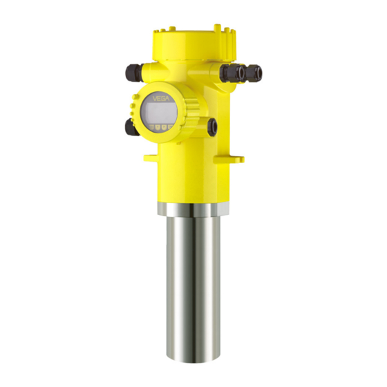
Page 54: Dimensions
119 mm ½ NPT (4.69") 169 mm (6.65") 116,5 mm 175 mm (4.59") (6.89") 90 mm 100 mm (3.54") (3.94") 143,5 mm (5.65") Fig. 19: Aluminium housing or stainless steel housing - Precision casting POINTRAC 31 • 8/16 mA/HART - four-wire... - Page 55 11 Supplement POINTRAC 31 ø 76,2 mm (3") Fig. 20: POINTRAC 31 Measuring range = Order length 152 mm or 304 mm (6 in/12 in) POINTRAC 31 • 8/16 mA/HART - four-wire...
- Page 56 Les lignes de produits VEGA sont globalement protégées par des droits de propriété intellectuelle. Pour plus d'informations, on pourra se référer au site http://www.vega.com VEGA lineas de productos están protegidas por los derechos en el campo de la propiedad industrial. Para mayor información revise la pagina web http://www.vega.com Линии...
- Page 57 Radiation protection 11 Fault rectification 44 Radiation safety officer 11 Functional principle 8 Radioactive emitter 25 Relay 28 Repair 46 Grounding 17 Replacement parts - Electronics module 10 Reset 31 Handling permit 10 POINTRAC 31 • 8/16 mA/HART - four-wire...
- Page 58 Sensor status 29 Serial number 7 Service hotline 45 Shielding 17 Simulation 30 Source holder 10 Status messages 40 Storage 9 Time 31 Type label 7 Unit 26 Voltage supply 16, 52 Water cooling 15 POINTRAC 31 • 8/16 mA/HART - four-wire...
- Page 59 Index POINTRAC 31 • 8/16 mA/HART - four-wire...
- Page 60 All statements concerning scope of delivery, application, practical use and operating conditions of the sensors and processing systems correspond to the information avail- able at the time of printing. © VEGA Grieshaber KG, Schiltach/Germany 2011 39411-EN-110525 Subject to change without prior notice...
Need help?
Do you have a question about the POINTRAC 31 and is the answer not in the manual?
Questions and answers