
Related Manuals for NACD 11.5

Summary of Contents for NACD 11.5
- Page 1 NACD Power Take-Off Service Manual 1016070AM 11.5" TP Power Take Off Includes Installation, Operation, Maintenance and Overhaul Instructions...
- Page 3 Phone: (800) 383-9204 (815) 282-7960 North American Clutch & Driveline (815) 282-9160 Rockford, Illinois www.naclutch.com...
- Page 4 NACD. WARRANTY: NACD’s limited Warranty is described in detail in this publication. It is the responsibility of the original pur- chaser or manufacturer, successive buyers, users, third parties or employees to make themselves aware of this warranty and all conditions it contains.
-
Page 5: Table Of Contents
TABLE OF CONTENTS INTRODUCTION General Information Replacement Parts Parts Shipment Preventative Maintenance/Troubleshooting Safety Sources of Service Information Warranty DESCRIPTION & SPECIFICATIONS General INSTALLATION Preliminary Checks Drive Ring Installation Pilot Bearing Installation Power Take-Off Installation to Engine Driving Member Installation Tips Torque Values for Fasteners Allowable Side Loads PREVENTATIVE MAINTENANCE... -
Page 6: Introduction
General Information This publication provides the information necessary for the operation and maintenance of the NACD Power Take Off specified on the cover of this manual. Specific engineering details and performance characteristics can be obtained from the Engineering Department of NACD, Rockford, Illinois, USA. -
Page 7: Parts Shipment
NACD. All returned parts, new or old, emanating from any of the above-stated changes will not be accepted for credit. -
Page 8: Safety
11.5" triple plate (TP) NACD power take-off is 2800 RPM. Sources of Service Information Each series of manuals issued by NACD is current at the time of printing. When required, changes are made to reflect advancing technology and improvements in state-of-the-art. -
Page 9: Warranty
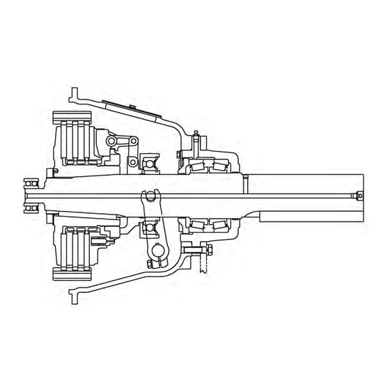
DESCRIPTIONS & SPECIFICATIONS General The NACD 11.5" TP Power Take-Off are engine mounted power take-offs that use cast iron two-piece housings and contain an integral triple plate clutch 11 1/2 inches in di- ameter. The engine drives the clutch through a drive ring that is bolted to the engine flywheel and connected to the clutch through internal teeth that mesh with external teeth on the clutch friction plate(s). -
Page 10: Installation
INSTALLATION Preliminary Checks Note: All measurements must be taken with the engine or motor mounted on its sup- ports after the flywheel and housing have been thoroughly cleaned. Measure and record the engine crankshaft or motor shaft end play using a dial indica- tor. - Page 11 Figure 3: Checking Drive Ring Surface of Flywheel Rotate the shaft through one entire revolution and note the face run out of the flywheel. The total indicator reading must not exceed .0005" .01 mm) per inch (25.4 mm) of flywheel diameter. Apply thrust onto crankshaft in one direction to prevent crankshaft end play from affecting run out measurement.
-
Page 12: Drive Ring Installation
Drive Ring Installation Clean the drive ring and flywheel of any dirt or debris as necessary. Position the drive ring against the flywheel and secure with eight hex head cap- screws. Torque the capscrews to the proper specifications given in Torque Values for Fasteners. -
Page 13: Power Take-Off Installation To Engine Driving Member
Power Take-Off Installation to Engine or Driving Member Clean the power take-off housing flange, flywheel housing flange, and pilot bearing bore or any debris. Install two alignment studs into the flywheel housing to assist with the power take-off installation. Install 2 or 3 guide studs in the flywheel housing. Position the power take-off against the flywheel housing, carefully aligning the main shaft pilot with the pilot bearing bore and the driving plates with the drive ring. -
Page 14: Installation Tips
Verify the clutch is adjusted according to the procedure outlined in Clutch Adjustment in Maintenance. Failure to do so will result in premature clutch wear and failure. NACD will not be responsible for any damage or injury resulting from improper ad- justment and/or lubrication. This includes any accessory drives and loads. - Page 15 Figure 6: Determining Deflection While Applying Side Loads The dial indicator should not be applied while the unit is operating. This could re- sult in damage to the dial indicator. Phone: (800) 383-9204 (815) 282-7960 North American Clutch & Driveline (815) 282-9160 Rockford, Illinois www.naclutch.com...
-
Page 16: Torque Values For Fasteners
Torque Values for Fasteners Note: All threads and bearing face to be lubricated with light oil film prior to assembly. Table 1. U.S. Standard Fine and Coarse Thread Capscrews, Bolts, and Nuts SAE Grade 5 SAE Grade 8 Thread Diameter lb - ft lb - ft 6 - 8... - Page 17 Table 3. Tapered Pipe Plugs (with thread lubricant) NPTF Size (in) Nm ( + or -5%) lb-ft (+ or -5%) Nm ( + or -5%) lb-ft (+ or -5%) 1/16-27 11.5 1/8-27 10.5 1/4-18 21.5 3/8-18 36.5 1/2-14 40.5 3/4-14...
-
Page 18: Allowable Side Loads
Allowable Side Loads Table 1. Allowable Side Load Pulls Force lbs. Shaft Distance X Speed 0” 1” 2” 3” 4” 5” 6” 7” 2000 7220 5680 4340 3540 3010 2630 2350 2100 2200 7030 5510 4210 3440 2930 2560 2290 2040 2400 6860... -
Page 19: Preventative Maintenance
Do not over grease. Excess grease can cause the main bearings to overheat. Pilot Bearings The pilot bearing supplied with most NACD power take-off units are pre-lubricated and sealed for life. No maintenance is required. Inspection is recommended every two years or when the power take-off is removed from the driving component for servicing. -
Page 20: Clutch Adjustment
Clutch Adjustment Note: New power take-offs must have clutch adjustment checked before being placed into service and after the first 4 to 8 hours of operation. This includes any power take- offs with new driving plates. New plates have a wear in period and the clutch may re- quire several adjustments before the new plates are worn in. -
Page 21: Assembly
Clutch Disassembly Support the power take-off with the clutch end facing up on a bench. Use wooden blocks under the power take-off. Remove the pilot bearing from the clutch shaft using a standard bearing puller. Use a 15/16" wrench to remove the jam nut and lock washer from the hose fitting located in the power take-off housing. - Page 22 See Ball Bearing Collar Disassembly for details regarding the ball bearing collar disassembly. Depress the adjusting ring lock pin with a screwdriver and unscrew the adjusting ring, removing it from the hub and the back plate. Remove the adjusting ring lock pin and spring from the floating plate.
- Page 23 Remove the grease fitting from the bearing carrier only if replacement is necessary. Set the clutch housing on the bench with the input end facing upward. Remove the two hex-head capscrews and lock washers from the throwout yoke. Tap one end of the shaft gently to expose one of the Woodruff keys.
- Page 24 Clutch Shaft and Housing Assembly Clean the bearing cones and clutch shaft with isopropyl solvent to remove any oil or grease residue. Note: Do not use any oil or paraffin based solvents. Use an arbor press to install the two bearing cones on the clutch shaft. Install the cones one from each end with the black faces butting against the shoulder on the clutch shaft.
- Page 25 Mark the 4th notch on the bearing retainer clockwise from the lock slot on the bear- ing carrier. Use the slot in line with or clockwise from the lock slot on the bearing carrier as the first slot. Remove the bearing retainer, front bearing cup and shaft assembly from the bearing carrier.
- Page 26 Note: Install the yoke with the retainer bolt threads facing the output side of the power take-off housing. Install one Woodruff key in the operating shaft. Push the operating shaft the other way to expose the other key slot in the center of the operating shaft.
- Page 27 Install the adjusting lock pin spring in the bore provided in the floating plate. Install the adjusting lock pin and press the pin and spring with a flat blade screwdriver while installing the adjusting ring halfway down the hub thread. Install the collar assembly to the floating plate using 4 headed pins, 8 spring washers, and 4 cotter pins.
- Page 28 Confirm that the hose assembly is not twisted or applying preload to the collar assembly. Install the pilot bearing according to Pilot Bearing Installation in Installation. Adjust the clutch according to Clutch Adjustment in Maintenance. Install the power take-off according to Installation. Phone: (800) 383-9204 (815) 282-7960 North American Clutch &...
- Page 29 1. Complete parts or products upon request must be returned transportation prepaid and also the claims submitted to NACD within sixty (60) days after completion of the in-warranty repair. 2. The warranty is void if, in the opinion of NACD, the failure of the part or product resulted from abuse, neglect, improper mainte nance or accident.
- Page 30 NOTICE NACD makes no warranty or guarantee of any kind, expressed, implied or other- wise, with regard to the information contained within this manual. NACD assumes no responsibility for any errors that may appear in this manual and shall not be li- able under any circumstances for incidental, consequential or punitive damages in connection with, or arising out of, the use of this manual.
- Page 32 North American Clutch & Driveline P.O. Box 15130 Rockford, IL. 61132 Phone: (800) 383-9204 Fax: (815) 282-9160 www.naclutch.com...
Need help?
Do you have a question about the 11.5 and is the answer not in the manual?
Questions and answers