Advertisement
Quick Links
Advertisement

Subscribe to Our Youtube Channel
Related Manuals for JBL 7130


Summary of Contents for JBL 7130
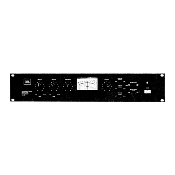
- Page 1 JBL 7130 INSTALLATION AND SERVICE MANUAL...
- Page 2 Architectural Specifications Line 170 mV RMS minimum ( - 1 3 . 5 dBm) The 7130 compressor/Iimiter shall have an output capacity of Microphone +18 dBm from 20 Hz-20 kHz, ± 1 dB and total harmonic distor- Input Pad 0 5.4 mV RMS minimum...
- Page 3 Installation Balanced Input Line with 5195 - 9 9 dBm The 7130 is suitable either for rack mounting in two E I A rack Transformer spaces without additional bracing or ventilation, or for counter- Microphone with 5901 133.5 dBm Transformer top placement.
- Page 4 JUMPER JUMPER (PINS 8 & 9) (PINS 8 & 9) JUMPER JUMPER (PINS 4 & 5) (PINS 4 & 5) 5195 F I G U R E 3 SWITCH S E L E C T S INPUT OPTION JUMPER (PINS 8 & 9) O P T I O N A L INPUT T R A N S F O R M E R (5195 or 5901)
- Page 5 Selects any one of three optional N O T E : When either the J B L Limit modes of 7130 5901 or 5195 transformer is used, the I N P U T 2 control cannot be used to prevent...
- Page 6 Input 1 & Balanced input impedance of 15kft Input 2 up to a level of +21 dB without optional 5195 matching/bridging transformer. Balanced input impedance of 600 ft using a 620 ft resistor connected to terminals HI and L O , up to a level of +21 dBm with optional 5195 transformer.
- Page 7 L I M I T E R MODE A . Control set to B. Input signal, 0 dBm. C . Control set to D. Control level set for -1-10 dBm at C O M P R E S S O R MODE A.
- Page 8 Table 2 and insert them per Figure 9, Table 3: Voltage Conversion The 7130 can be operated from either 120 V A C or 240 V A C , 50/60 Hz source. The line voltage selector, a Molex commoning connector, Figure 7, changes the primary connections of the (Power SW-S1 power transformer.
- Page 9 WARNING T H I S S E C T I O N O F T H E M A N U A L C O N T A I N S S E R V I C E I N S T R U C T I O N S T A B L E 2 (120 V A C commoning wire code) F O R U S E B Y Q U A L I F I E D S E R V I C E P E R S O N N E L O N L Y .
-
Page 10: Gain R E D U C T I O N
WARNING T H I S S E C T I O N O F T H E M A N U A L C O N T A I N S S E R V I C E I N S T R U C T I O N S F O R U S E BY Q U A L I F I E D S E R V I C E P E R S O N N E L O N L Y . - Page 11 8. Adjust the oscillator output level until the output level of Gain Reduction, 0 V U Meter Calibration the 7130 is +20 dBm. Input level to the 7130 must measure 1. Remove the top cover. - 7 d B m , + 3 dBm.
- Page 12 F O R U S E B Y Q U A L I F I E D S E R V I C E P E R S O N N E L O N L Y . 7130 Exploded View and Parts List F I G U R E 13.
- Page 13 WARNING T H I S S E C T I O N O F T H E M A N U A L C O N T A I N S S E R V I C E I N S T R U C T I O N S FOR U S E BY Q U A L I F I E D S E R V I C E P E R S O N N E L O N L Y .
- Page 14 WARNING T H I S S E C T I O N O F T H E M A N U A L C O N T A I N S S E R V I C E I N S T R U C T I O N S F O R USE BY Q U A L I F I E D S E R V I C E P E R S O N N E L O N L Y .
- Page 15 WARNING T H I S S E C T I O N O F T H E M A N U A L C O N T A I N S S E R V I C E I N S T R U C T I O N S F O R U S E BY Q U A L I F I E D S E R V I C E P E R S O N N E L O N L Y .
Need help?
Do you have a question about the 7130 and is the answer not in the manual?
Questions and answers