Advertisement
Available languages
Available languages
Quick Links
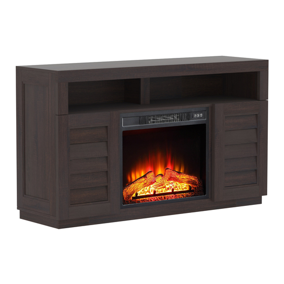
Ellis Shutter Media Fireplace Console
If you have any questions regarding assembly or if parts are missing, DO NOT return this item to the
store where it was purchased. Please call our customer service number and have your instructions
and parts list ready to provide the model name, part name or factory number:
Pacific Standard Time: 8:30 a.m. - 4:30 p.m., Monday - Friday
Or visit our web site 24 hours a day, 7 days a week for product assistance at
THIS INSTRUCTION BOOKLET CONTAINS IMPORTANT SAFETY INFORMATION.
Stock # BH18-084-097-23
ADULT ASSEMBLY REQUIRED
www.whalenstyle.com
Or e-mail your request to parts@whalenfurniture.com
PLEASE READ AND KEEP FOR FUTURE REFERENCE.
Date 2018-07-13 Rev. 0001-A Factory: HESLTD
866-942-5362
LOT NUMBER:
DATE PURCHASED:
/
/
Advertisement

Subscribe to Our Youtube Channel
Related Manuals for Better Homes and Gardens Ellis Shutter BH18-084-097-23


Summary of Contents for Better Homes and Gardens Ellis Shutter BH18-084-097-23
- Page 1 LOT NUMBER: DATE PURCHASED: Ellis Shutter Media Fireplace Console Stock # BH18-084-097-23 ADULT ASSEMBLY REQUIRED If you have any questions regarding assembly or if parts are missing, DO NOT return this item to the store where it was purchased. Please call our customer service number and have your instructions and parts list ready to provide the model name, part name or factory number: 866-942-5362 Pacific Standard Time: 8:30 a.m.
- Page 2 M A X I M U M R E C O M M E N D E D W E I G H T L O A D S MANUFACTURER: Whalen Furniture Manufacturing CATALOG: Ellis Shutter Media Fireplace Console MODEL # BH18-084-097-23 MADE IN CHINA HOLDS MOST 42"- 70 "...
- Page 3 IMPORTANT Before you begin: Open, identify and count all parts prior to assembly. Lay out parts on a flat and non- abrasive surface. You will need the parts identified on page 4 and 5 of this instruction manual. NOTE: IT IS VERY IMPORTANT TO USE GLUE WITH DOWELS. EXCESS GLUE CAN BE WIPED OFF WITH DAMP CLOTH.
-
Page 4: Parts And Hardware List
Parts and Hardware List Please read completely through the instructions and verify that all listed parts and hardware are present before beginning assembly. A- Top Panel (Qty. 1) B- Fixed Shelf (Qty. 1) C- Bottom Panel (Qty. 1) D- Upper Partition Panel (Qty. 1) E- Upper Partition Molding (Qty. - Page 5 Parts and Hardware List Please read completely through the instructions and verify that all listed parts and hardware are present before beginning assembly. V- Upper Back Panel (Qty. 1) W- Lower Back Panel (Qty. 2) X- Stopper Rail (Qty. 1) Fireplace Insert (Qty.
- Page 6 Assembly Instructions Cam Bolt (31 used in this step) ② 1. Unpack the unit and confirm that you have all the hardware and required parts. Assemble the unit on a carpeted floor or the empty carton to avoid any scratch. 2.
- Page 7 Assembly Instructions Cam Bolt (20 used in this step) ② 3. Securely screw the Cam Bolts (2) into the designated small holes on the Side Panels (I and J), the Stretchers (F, P and Q) and the Middle Stiles (M and N).
- Page 8 Assembly Instructions Cam Lock M8 x 30 mm Wood Dowel (3 used in this step) (2 used in this step) ① ③ 4. Insert two 30 mm Wood Dowels (3) into the inner holes of the Left Lower Partition Panel (K). Tap in with a rubber mallet, if necessary.
- Page 9 Assembly Instructions Cam Lock M8 x 30 mm Wood Dowel (3 used in this step) (2 used in this step) ① ③ 6. Repeat the same procedure to combine the Right Lower Partition Panel (L) with the Right Middle Stile (N).
- Page 10 Assembly Instructions Cam Lock M8 x 30 mm Wood Dowel (3 used in this step) (2 used in this step) ① ③ 7. Attach the Middle Crossbar (O) to the Fixed Shelf (B) with two 30 mm Wood Dowels (3) and three Cam Locks (1).
- Page 11 Assembly Instructions M8 x 30 mm Wood Dowel Cam Lock (4 used in this step) (4 used in this step) ③ ① 8. Attach the Lower Partition Panels (K and L) to the Fixed Shelf (B) with four Cam Locks (1) and four Wood Dowels (3).
- Page 12 Assembly Instructions Cam Lock M8 x 30 mm Wood Dowel (4 used in this step) (4 used in this step) ① ③ 9. Attach Side Panels (I and J) to the Fixed Shelf (B) with four Wood Dowels (3) and four Cam Locks (1).
- Page 13 Assembly Instructions Cam Lock M8 x 30 mm Wood Dowel (4 used in this step) (4 used in this step) ① ③ 10. Attach the Left Side Molding (G) to Left Side Panel (I) with two Wood Dowels (3) and two Cam Locks (1).
- Page 14 Assembly Instructions Cam Bolt (2 used in this step) ② 12. Securely screw the Cam Bolts (2) into the designated small holes on the top of Fixed Shelf (B).
- Page 15 Assembly Instructions Cam Lock Wood Dowel (2 used in this step) (2 used in this step) ① ③ 13. Attach Upper Partition Molding (E) to Upper Partition Panel (D) with two Wood Dowels (3) and two Cam Locks (1).
- Page 16 Assembly Instructions Cam Lock M8 x 30 mm Wood Dowel (2 used in this step) (1 used in this step) ① ③ 14. Attach the Upper Partition Panel (D) to the Fixed Shelf (B) with two Cam Locks (1) and one Wood Dowel (3).
- Page 17 Assembly Instructions 27mm 21mm 1/4" x 12 mm Bolt Corner Connector (2 used in this step) (2 used in this step) ⑤ ④ 15. Fasten two Corner Connectors (5) to the Top Panel (A) with two 12 mm Bolts (4).
- Page 18 Assembly Instructions 1/4" x 12 mm Bolt Cam Lock M8 x 30 mm Wood Dowel (2 used in this step) (4 used in this step) (1 used in this step) ④ ① ③ 16. Attach the Top Front Stretcher (F) to the Top Panel (A) with one 30 mm Wood Dowel (3) and four Cam Locks (1).
- Page 19 Assembly Instructions Cam Lock M8 x 30 mm Wood Dowel (8 used in this step) (5 used in this step) ① ③ 18. Glue five Wood Dowels (3) into the inner holes on the vertical panels (D, I and J). 19.
- Page 20 Assembly Instructions Cam Lock (4 used in this step) ① 20. Combine the Bottom Front Stretcher (P), Back Stretcher (Q) and Side Stretchers (R) together with four Cam Locks (1).
- Page 21 Assembly Instructions Cam Lock M8 x 30 mm Wood Dowel (12 used in this step) (10 used in this step) ① ③ 21. Attach the assembled base to the Bottom Panel (C) with the 30 mm Wood Dowels (3) and the Cam Locks (1).
- Page 22 Assembly Instructions M3.5 x 15 mm Pan Head Screw Angle Metal Bracket (8 used in this step) (2 used in this step) ⑦ ⑧ 22. With the pilot holes as a guide, align and attach two Angle Metal Brackets (8) to the front corners of the assembled base, using four 15 mm Screws (7) per bracket.
- Page 23 Assembly Instructions Floor Leveler (2 used in this step) ⑨ 23. Screw two Floor Levelers (9) into the threaded sockets on the Angle Metal Brackets (8) and set to the correct height.
- Page 24 Assembly Instructions Cam Bolt (4 used in this step) ② 24. Securely screw the Cam Bolts (2) into the designated small holes on the top of Bottom Panel (C).
- Page 25 Assembly Instructions Cam Lock M8 x 30 mm Wood Dowel M4 x 50 mm Screw ⑥ (4 used in this step) (8 used in this step) (4 used in this step) ① ③ 25. Glue eight Wood Dowels (3) into the inner holes on the vertical panels (I, J, K and L). 26.
- Page 26 Assembly Instructions M3.5 x 12 mm Flat Head Screw Straight Metal Bracket (4 used in this step) (2 used in this step) ⑩ 27. Now, go back and securely tighten all the Cam Locks and the Screws. Make sure that all the parts are tight and there are no gaps between the parts.
- Page 27 Assembly Instructions M3.5 x 15 mm Washer Head Screw (38 used in this step) 30. Pick up the Upper Back Panel (V) and align the pre-drilled holes against the upper long edge with the pilot holes on the back of the Top Panel (A). Attach the Upper Back Panel (V) in place using the provided Washer Head Screws (11).
- Page 28 Assembly Instructions 32. Stand the unit upright. 33. Pick up the Right Door (T) and attach the extended Hinge Arms to the Hinge Bases installed on Right Side Panel (J). Loosen the bolt on the back of Hinge Base for a comfortable fit. Align and insert the “U” slot on Hinge Arm under the bolt head on the back of Hinge Base.
- Page 29 Assembly Instructions Shelf Support Cam Lock Cover Rubber Bumper (8 used in this step) (20 used in this step) (4 used in this step) ⑫ ⑬ ⑭ 36. With the doors open, insert the Shelf Supports (12) into the desired holes in the sides of the side compartments.
- Page 30 Assembly Instructions Insert Screw (6 used in this step) 39. Unpack the fireplace insert from the inner box and follow the instructions to install the Top Trim and Side Trims to the fireplace insert. 40. Lift the fireplace insert carefully into the back of the assembled mantel and center it in the opening. DO NOT drag the insert across the Bottom Panel (C) as it may scratch the unit.
- Page 31 Assembly Instructions NOTE: To prevent your TV from tipping, you must install the Strip Stopper if you place your flat panel television directly on the console. Otherwise, skip to step 4 3 . 42. Remove the paper backing from the Stopper Rail (X), then properly align the Stop Rail with the top edge of the stopper template on Top Panel (A).
- Page 32 Assembly Instructions Tools required (not provided): Phillips screwdriver, stud finder, power drill and 3 mm/0.1 in drill bit. 44. Ask for assistance to position the assemble fireplace at the desired location against a wall. If necessary, adjust the installed Floor Levelers (9) at the bottom of the Base to level the unit. Now, follow the instructions printed on the plastic bag containing the Tipping Restraint Hardware to attach the tip-over restraints to the unit and the wall.
-
Page 33: Care And Maintenance
Care and Maintenance Use a soft, clean cloth that will not scratch the surface when dusting. Use of furniture polish is not necessary. Should you choose to use polish, test first in an inconspicuous area. Using solvents of any kind on your furniture may damage your furniture’s finish. ... - Page 35 NÚMERO de LOTE: FECHA de COMPRA: / Consola con Chimenea Ellis Shutter Serie # BH18-084-097-23 ENSAMBLE REQUERIDO POR ADULTO Si tiene alguna pregunta acerca del ensamble o si alguna parte está faltante, no retorne esté producto a la tienda donde lo compró. Por favor llame a nuestro departamento de ayuda al cliente teniendo su instructivo y lista de partes para proveer el modelo, nombre de parte o el número de fábrica: 866-942-5362 Hora Estándar del Pacífico: 8:30 am - 4:30 pm de Lunes a Viernes...
- Page 36 M Á X I M O P E S O R E C O M E N D A D O FABRICANTE: Whalen Furniture Manufacturing CATALOGO: Consola con Chimenea Ellis Shutter MODELO # BH18-084-097-23 PARA TVs DE PANTALLA PLANA HECHO EN CHINA DE HASTA 42"-70"...
- Page 37 IMPORTANTE Antes de comenzar: Abra, identifique y cuente todas las partes antes del ensamble. Coloque las piezas sobre una superficie plana y no abrasiva. Tendrá que las partes identificadas en la página 4 y 5 de este manual de instrucciones. NOTA: ES MUY IMPORTANTE PARA EL USO DE GOMA CON LOS PERNOS DE MADERA.
- Page 38 Lista de partes y material de ferretería Por favor lea completamente las instrucciones y verifique que estén todas las partes antes de iniciar el ensamblado. A- Panel superior (Cant. 1) B- Repisa fija (Cant. 1) C- Panel inferior (Cant. 1) D- Panel divisor superior (Cant.
- Page 39 Lista de partes y material de ferretería Por favor lea completamente las instrucciones y verifique que estén todas las partes antes de iniciar el ensamblado. V- Panel (Cant. 1) W- Panel inferior posterior (Cant. 2) X- Riel tope (Cant. 1) Superior posterior Inserto de chimenea (Cant.
- Page 40 Instructivo de ensamble Perno de fijación (31 usados en este paso) ② 1. Desempacar la unidad y confirmar que se tiene todo el material de ferretería y partes requeridas. Ensamblar la unidad en un piso alfombrado o en el cartón vacío para evitar rasguños. 2.
- Page 41 Instructivo de ensamble Perno de fijación (20 usados en este paso) ② 3. Atornillar los pernos de fijación (2) en los agujeros chicos designados en los paneles laterales (I y J), en los soportes (F, P y Q) y en los soportes medios (M y N).
- Page 42 Instructivo de ensamble Tuerca de fijación Clavija de madera de (3 usados en este paso) M8 x 30 mm (2 usados en este paso) ① ③ 4. Insertar 2 clavijas de madera de 30 mm (3) en los agujeros interiores del panel divisor izquierdo (K). Golpear ligeramente con el mazo de goma, si es necesario.
- Page 43 Instructivo de ensamble Tuerca de fijación Clavija de madera de (3 usados en este paso) M8 x 30 mm (2 usados en este paso) ① ③ 6. Repetir el mismo procedimiento para combinar el panel divisor derecho inferior (L) con el soporte derecho medio (N).
- Page 44 Instructivo de ensamble Tuerca de fijación Clavija de madera de (3 usados en este paso) M8 x 30 mm (2 usados en este paso) ① ③ 7. Adjuntar el soporte medio (O) a la repisa fija (B) con 2 clavijas de madera de 30 mm (3) y 3 tuercas de fijación (1).
- Page 45 Instructivo de ensamble Clavija de madera de Tuerca de fijación M8 x 30 mm (4 usados en este paso) (4 usados en este paso) ① ③ 8. Adjuntar el panel divisor inferior (K y L) a la repisa fija (B) con 4 tuercas de fijación (1) y 4 clavijas de madera (3).
- Page 46 Instructivo de ensamble Tuerca de fijación Clavija de madera de (4 usados en este paso) M8 x 30 mm (4 usados en este paso) ① ③ 9. Adjuntar los paneles laterales (I y J) a la repisa fija (B) con 4 clavijas de madera (3) y 4 tuercas de fijación (1).
- Page 47 Instructivo de ensamble Tuerca de fijación Clavija de madera de (4 usados en este paso) M8 x 30 mm (4 usados en este paso) ① ③ 10. Adjuntar la moldura izquierda (G) al panel izquierdo (I) con 2 clavijas de madera (3) y 2 tercas de fijación (1).
- Page 48 Instructivo de ensamble Perno de fijación (2 usados en este paso) ② 12. Atornillar los pernos de fijación (2) en los agujeros chicos designados arriba de la repisa fija (B).
- Page 49 Instructivo de ensamble Tuerca de fijación Clavija de madera (2 usados en este paso) (2 usados en este paso) ① ③ 13. Adjuntar la moldura divisora superior (E) al panel divisor superior (D) con 2 clavijas de madera (3) y 2 tuercas de fijación (1).
- Page 50 Instructivo de ensamble Tuerca de fijación Clavija de madera de (2 usados en este paso) M8 x 30 mm (1 usado en este paso) ① ③ 14. Adjuntar el panel divisor superior (D) a la repisa fija (B) con 2 tuercas de fijación (1) y una clavija de madera (3).
- Page 51 Instructivo de ensamble 27mm 21mm Perno de 1/4" x 12 mm Conector de esquina (2 usados en este paso) (2 usados en este paso) ⑤ ④ 15. Sujetar 2 conectores de esquina (5) al panel superior (A) con 2 pernos de 12 mm (4).
- Page 52 Instructivo de ensamble Tuerca de fijación Clavija de madera de Perno de 1/4" x 12 mm (4 usados en este paso) M8 x 30 mm (2 usados en este paso) (1 usado en este paso) ① ④ ③ 16. Adjuntar el soporte superior frontal (F) al panel superior (A) con una clavija de madera de 30 mm (3) y 4 tuercas de fijación (1).
- Page 53 Instructivo de ensamble Tuerca de fijación Clavija de madera de (8 usados en este paso) M8 x 30 mm (5 usados en este paso) ① ③ 18. Pegar 5 clavijas de madera (3) en los agujeros internos en los paneles verticales (D, I y J). 19.
- Page 54 Instructivo de ensamble Tuerca de fijación (4 usados en este paso) ① 20. Combinar el soporte inferior frontal (P), el soporte posterior (Q) y los soportes laterales (R) con 4 tuercas de fijación (1).
- Page 55 Instructivo de ensamble Tuerca de fijación Clavija de madera de (12 usados en este paso) M8 x 30 mm (10 usados en este paso) ① ③ 21. Adjuntar la base ensamblada al panel inferior (C) con las clavijas de madera de 30 mm (3) y las tuercas de fijación (1).
- Page 56 Instructivo de ensamble Perno de cabeza redonda de Soporte de metal triangular M3.5 x 15 mm (2 usados en este paso) (8 usados en este paso) ⑧ ⑦ 22. Con los agujeros pilotos como guía, alinear y adjuntar 2 soportes de metal triangular (8) a las esquinas frontales de la base ensamblada, usando 4 pernos de 15 mm (7) por soporte.
- Page 57 Instructivo de ensamble Nivelador de piso (2 usados en este paso) ⑨ 23. Atornillar 2 niveladores de piso (9) en los espacios roscados en los soportes de metal triangular (8) y ajustar a la altura correcta.
- Page 58 Instructivo de ensamble Perno de fijación (4 usados en este paso) ② 24. Atornillar los pernos de fijación (2) en los agujeros chicos designados arriba del panel inferior (C).
- Page 59 Instructivo de ensamble Tuerca de fijación Clavija de madera de Perno de M4 x 50 mm ⑥ (4 usados en este paso) M8 x 30 mm (4 usados en este paso) (8 usados en este paso) ① ③ 25. Pegar 8 clavijas de madera (3) en los agujeros internos en los paneles verticales (I, J, K y L). 26.
- Page 60 Instructivo de ensamble Perno de cabeza plana de Soporte de metal recto M3.5 x 12 mm (2 usados en este paso) (4 usados en este paso) ⑩ 27. Ahora, volver y apretar todas las tuercas de fijación y los pernos. Asegurar que todas las partes estén apretadas y de que no hay huecos entre las partes.
- Page 61 Instructivo de ensamble Perno de cabeza de arandela de M3.5 x 15 mm (38 usados en este paso) 30. Levantar el panel superior posterior (V) y alinear los agujeros pre-perforados contra el borde superior largo con los agujeros pilotos en la parte posterior del panel superior (A). Adjuntar el panel superior posterior (V) en su lugar usando los pernos de cabeza de arandela provistos (11).
- Page 62 Instructivo de ensamble 32. Poner la unidad en posición vertical. 33. Tomar la puerta derecha (T) y adjuntar los brazos de bisagras extendidos a las bases de bisagras instaladas en el panel derecho (J). Aflojar el perno detrás de la base para un ajuste fácil. Alinear e insertar el espacio “U”...
- Page 63 Instructivo de ensamble Soporte de repisa Tapa de la tuerca de Tope de plástico (8 usados en este paso) fijación (4 usados en este paso) (20 usados en este paso) ⑫ ⑭ ⑬ 36. Con las puertas abiertas, insertar los soportes de repisa (12) en los agujeros deseados en los lados del compartimiento lateral.
- Page 64 Instructivo de ensamble Perno del inserto (6 usados en este paso) 39. Desempacar el inserto de chimenea de la caja interior y seguir las instrucciones para instalar el borde superior y los bordes laterales al inserto de chimenea. 40. Meter el inserto de chimenea en la parte posterior del mantel ensamblado y centrar en la abertura. arrastrar el inserto a través del panel inferior (C) porque puede rayar la unidad.
- Page 65 Instructivo de ensamble NOTA: Para prevenir que su TV se incline, debe instalar la tira tope si instala su TV plana sobre la consola. De lo contrario, vaya al paso 4 3 . 42. Retirar el respaldo de papel del riel tope (N), luego alinear el riel tope con el borde superior del templete de ltope en el panel superior (A).
-
Page 66: Instrucciones De Ensamblaje
Instrucciones de ensamblaje Herramientas necesarias (no incluidas): Desarmador estrella, detector de vigas, taladro eléctrico y taladro de 3mm (0.1"). 44. ida assistencia para posicionar la chimenea ensamblada en el lugar deseado contra la pared. Si fuera necessario, ajuste los niveladores de piso (9) pre-adjuntados en la parte inferior de la base para nivelar la unidad. - Page 67 Mantenimiento y Cuidados Use una toalla suave y limpia para evitar daños y rayaduras. Uso de cera para pulir muebles no es necesario. Si desea usar cera, pruebela en un área que no sea visible para revisar su funcionamiento. ...
Need help?
Do you have a question about the Ellis Shutter BH18-084-097-23 and is the answer not in the manual?
Questions and answers