
Subscribe to Our Youtube Channel
Related Manuals for ADEEPT B08LGR7RBF

Summary of Contents for ADEEPT B08LGR7RBF
- Page 1 Assembly instructions Adeept Flash Christmas Tree DIY Kit Colorful 3D Xmas Christmas Tree Led DIY Kits ASIN: B08LGR7RBF Product: https://www.amazon.com/dp/B08LGR7RBF...
- Page 2 1.Work Schematic:...
- Page 3 NOTE: Users can complete the installation by PCB silk screen and component listing!
-
Page 4: Component Description
2. Component Description 1>. 3pcs 1K Metal Film Resistor 2>. 1pcs 2.2K Metal Film Resistor... - Page 5 3>. 3pcs 10K Metal Film Resistor 4>. 3pcs 47uF 16V Electrolytic Capacitor 5>. 19pcs 3mm White LED 6>. 3pcs S9014 Transistor TO-92 7>. 1pcs PCB CTR-30A 8>. 3pcs 1K Metal Film Resistor 9>. 3pcs 10K Metal Film Resistor 10>. 3pcs 47uF 16V Electrolytic Capacitor 11>.
-
Page 6: Installation Steps
3.Installation Steps: (1) -- Install Board CTR-30A... - Page 7 Step 1: Install 3pcs 1K Metal Film Resistor on R2,R4,R6...
- Page 8 Step 2: Install 3pcs 10K Metal Film Resistor on R1,R3,R5 Step 3: Install 1pcs 2.2K Metal Film Resistor on R7...
- Page 9 Step 4: Install 18pcs LED. Tips: A. Note the direction of the LED B. Control distance between PCB edge and LED head(Two ways).
- Page 10 1). User can bend the LED pin at first after determining the distance and then insert LED to PCB through hole; 2). Insert LED to PCB through hole at first.Then determine the distance.Bend the LED pin at last.
- Page 11 Step 5: Install 3pcs 47uF 16V Electrolytic Capacitor...
- Page 12 Step 6: Install 3pcs TO-92 S9014 Transistor Tips: It is better to bend S9014's pin so that 2pcs PCB CTR-30A and CTR-30B can better splicing.
- Page 13 Great!! CTR-30A has been installed completed.
- Page 14 (2) -- Install Board CTR-30B...
- Page 15 Step 7: Install 3pcs 1K Metal Film Resistor on R2,R4,R6...
- Page 16 Step 8: Install 3pcs 10K Metal Film Resistor on R1,R3,R5...
- Page 17 Step 9: Install 18pcs LED...
- Page 19 Step 10: Install 3pcs 47uF 16V Electrolytic Capacitor Step 11: Install 3pcs TO-92 S9014 Transistor...
- Page 20 Step 12: Connect 5V to CTR-30A and CTR-30B.Preliminary welding success if LEDs are blinking automatically...
- Page 21 (3) -- Stitching Board CTR-30A and CTR-30B Step 13: Align the two positioning heads on CTR-30A and CTR-30B and then fixed with tin.
- Page 22 (4) -- Install Board CTR-30C...
- Page 23 Step 14: Install Power Socket.Use a superfluous pin to fixed the power supply socket.This pin can come from resistor.
- Page 25 Step 15: Install 1pcs Self-Locking Switch. Note the direction of switch. The concave side is close to the PCB edge. Step 16: Install battery box and fixed by screw/nut Tips: First peel the insulation of the wire, and then welding fixed, and then cut off the excess wire...
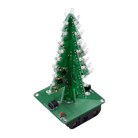
- Page 27 Step 17: Fixed CTR-30A and CTR-30B on CTR-30C.Align the two positioning heads and then fixed with tin. Step 18:Install the top LED.Note the positive and negative of LED.At this point, Congratulations!!! installation is complete.
- Page 28 Congratulations!!!
Need help?
Do you have a question about the B08LGR7RBF and is the answer not in the manual?
Questions and answers