Table of Contents
Advertisement
Quick Links
Advertisement
Table of Contents

Subscribe to Our Youtube Channel
Summary of Contents for JBL MS-A5001
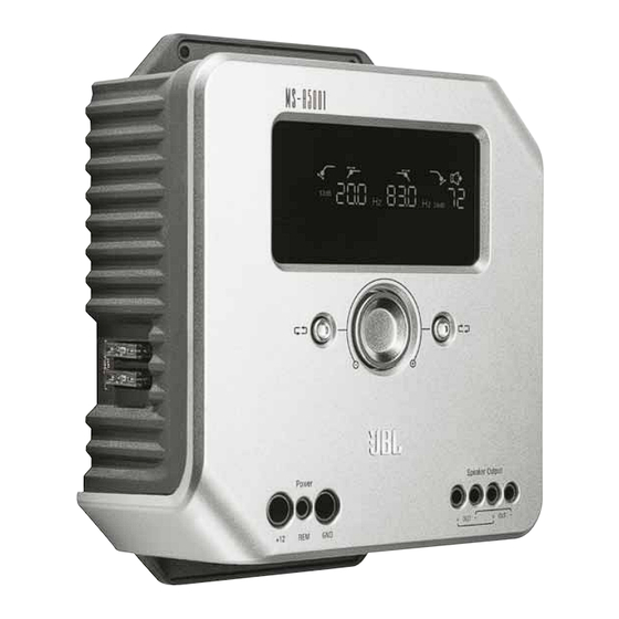
- Page 1 Ms-A5001 Digital signal processing amplifier User GUide...
- Page 2 40 A 40 A 2 x 40A 1 x 80A Input Level Input Output...
-
Page 3: Fcc Regulations
Only the input-level controls are analog. Will I lose my settings if I disconnect the amplifier or the car’s battery? No. The MS-A5001 stores all of the DSP settings in nonvolatile memory, so you will not lose any settings if power is removed. - Page 4 How does the digital input mixer work? The MS-A5001 converts the signals from each RCA-type input connector into digital signals and sends them to its digital signal processor. The DSP routes the signals to the speaker output according to the selections in the input mixer.
- Page 5 My factory-installed head unit doesn’t include a remote-turn-on wire. What should I do? MS-series amplifiers include signal-sensing turn-on. They never require a remote turn-on connection. The amplifier will sense the presence of an audio signal on its inputs, and it will turn on automatically. A few minutes after the signal stops or after the vehicle’s radio is turned off, the amplifier will turn itself off automatically.
- Page 6 1) JBL MS-series amplifiers include many features not found on conventional car-audio amplifiers. As a result, the setup procedure for JBL MS-series amplifiers is different from that of conventional car-audio amplifiers. Care- fully read and understand these instructions before attempting installation.
- Page 7 This amplifier sends input channels 1 and 2 to the corresponding RCA outputs. Using these outputs, you can easily add additional amplifiers. For example: When using the MS-A5001 for a subwoofer, you could use these outputs for a second subwoofer amplifier or a high-frequency amplifier to complete a system.
- Page 8 *Muted when in “Setup Mode” Adjustment- selection indicator When lit, the parameter above is selected for adjustment. Protection Amplifier Protection Circuit Engaged Channel id Indicates the amplifier in the display. (As the MS-A5001 is a possible input channels exist.)
-
Page 9: Initial Setup
Ms-A5001 User CONTrOLs Rotary Encoder Rotates clockwise (CW) and counterclockwise (CCW). Each detent represents a value increase (CW) or decrease (CCW). Counterclockwise (CCW) Button Move selectable op- tion counterclockwise (CCW) one value. Pressing both the left and right buttons simul- taneously for specified time periods accesses various modes of the amplifier. - Page 10 To Set the Input Level: 1. Move the input-level control to the Hi position (or Hi2 if you are connecting to a factory-installed sys- tem with open-circuit protection). 2. Set the bass, treble, balance and fader controls on your head unit to the center (or flat) positions. Set “loudness”...
-
Page 11: Output Levels
Adjustments made to the control when the amplifier(s) are off aren’t recognized. How to Pair the MS-WBC Wireless Bass Control with the MS-A5001 The optional MS-WBC wireless bass controller must be paired to the amplifier in order to be used. -
Page 12: System Diagrams
Inputs can be Channel 1 only or both Channel 1 and 2, depending upon how the pass-through output is to be used. In this confIguration, subwoofers are connected in parallel at the dual mono output of MS-A5001. Four-ohm or 8-ohm subwoofers should be used. - Page 13 sYsTeM diAGrAMs (dvC sUBs) SERIES WIRED VOICE COILS 24dB 24dB Example of filter and input settings for this configuration PARALLEL WIRED VOICE COILS 24dB 24dB Example of filter and input settings for this configuration Inputs can be Channel 1 only or both Channel 1 and 2, depending upon how the pass-through output is to be used.
-
Page 14: Series Connection
Use these formulas to calculate total series or parallel resistance of multiple speakers or voice coils on the MS-A5001 amplifier. “R” with a number denotes each nominal voice-coil impedance (such as R 1 and R 2 ). R t is the total combined nominal impedance presented to the amplifier.


Need help?
Do you have a question about the MS-A5001 and is the answer not in the manual?
Questions and answers