Digital Equipment DECswitch 900EF Installation And Configuration Manual
Hide thumbs
Also See for DECswitch 900EF:
- Installation and configuration manual (130 pages) ,
- Installation and configuration manual (110 pages)

Related Manuals for Digital Equipment DECswitch 900EF


Summary of Contents for Digital Equipment DECswitch 900EF
- Page 1 DECswitch 900EF Installation and Configuration Part Number: EK-DEFBA-IN. D01 May 1996 This manual describes how to install and configure the DECswitch 900EF module. Revision/Update Information: This is a revised manual.
- Page 2 Digital Equipment Corporation makes no representations that the use of its products in the manner described in this publication will not infringe on existing or future patent rights, nor do the descriptions contained in this publication imply the granting of licenses to make, use, or sell equipment or software in accordance with the description.
-
Page 3: Table Of Contents
What is the DECswitch 900EF?........ - Page 4 Front Panel Features ............1-9 Back Panel Features .
- Page 5 [5] Set Out-of-Band Interface IP Address ........4-12 [6] Enable/Disable BootP .
- Page 6 If the Process Does not Complete ..........5-22 When the DLU Process is Complete .
- Page 7 In this appendix............C-1 Operating Specifications .
- Page 8 Tables Front Panel LEDs and Connectors ..........1-9 Front Panel LEDs and Connectors .
-
Page 9: Preface
Overview About this Manual This manual describes how to install the DECswitch 900EF in a DEChub 900 MultiSwitch. (How to install the DECswitch 900EF in the DEChub ONE docking station is described in the DEChub ONE Installation manual.) This manual also... -
Page 10: Organization
Organization This manual is organized as follows: Section Description Provides an overview of the DECswitch 900EF, describes its features, and lists front and back panel features. Provides instructions for installing the module in a DEChub 900 MultiSwitch. Provides instructions for installing the setup port cable. -
Page 11: Associated Documents
Associated Documents The following documents provide information relating to the module. To order any of the following documents, refer to the section titled How to Order Additional Documentation. Title and Order Description Number Ethernet Switch Provides information for installing and configuring full Enterprise RMON RMON firmware upgrade that supports all nine RMON Upgrade... - Page 12 Title and Order Description Number DEChub Network Describes the functions and features of Digital’s HUB- Modules 900-Series based 900-Series switching products. Switch Reference EK-SWTCH-HR Bridge and Describes how bridges are used to create extended local Extended area networks (LANs). This includes the use of bridges LAN Reference in extended LAN configurations, information on LAN EK-DEBAM-HR...
-
Page 13: Conventions
Conventions Overview This book uses the following conventions. Convention Description Bold Type Indicates user input Indicates system output Monospaced Type 16.20.54.156 The format of an IP address is the standard 4- octet dotted decimal notation, where each octet of the address is represented as a decimal value, separated by a decimal point (.). -
Page 14: Correspondence
To read the Bulletin Board System, set your modem to 8 bits, no parity, 1 stop bit and dial 508-486-5766 (U.S.) The Digital Equipment Corporation Network Products Business Home Page on the World Wide Web is at the following addresses: North America: http://www.networks.digital.com... -
Page 15: How To Order Additional Documentation
P.O. Box CS2008 Puerto Rico) Nashua, New Hampshire 03061 (Place prepaid orders from Puerto Rico with the local Digital subsidiary: 809-754-7575) By Mail DIGITAL EQUIPMENT of CANADA LTD. (Canada) 940 Belfast Road Ottawa, Ontario, Canada K1G 4C2 Attn.: A&SG Business Manager Internationally DIGITAL EQUIPMENT CORPORATION Attn.: A&SG Business Manager... -
Page 17: Safety
Safety Overview Any warning or caution that appears in this manual is defined as follows:. WARNING Contains information to prevent personal injury. CAUTION Contains information to prevent damage to equipment. VORSICHT Enthält Informationen, die beachtet werden müssen um den Benutzer vor Schaden zu bewahren. ACHTUNG Enthält Informationen, die beachtet werden müssen um die Gerate vor Schaden zu bewahren... - Page 18 The cautions that must be observed for the hardware described in this manual are listed below in English, German, French, and Spanish. CAUTION This action deletes all configured settings and replaces them with factory default values. All configuration settings will be lost. ACHTUNG Bei diesem Vorgang werden alle Konfigurationseinstellungen gelöscht und die...
- Page 19 WARNING Some fiber optic equipment can emit laser or infrared light that can injure your eyes. Never look into an optical fiber or connector port. Always assume the cable is connected to a light source. VORSICHT Bestimmte Lichtleitergeräte können für die Augen gefährliches Laser- oder Infrarotlicht abstrahlen.
- Page 20 CAUTION If power is interrupted during Stage 3 of the DLU process, the firmware image can become corrupted. Do not turn off power to the unit or perform any action that can cause the unit to lose power during Stage 3 of the DLU process. ACHTUNG Solite während der Phase 3 des DLU-Prozesses eine Unterbrechung der Stromversorgung eintreten, kann das...
-
Page 21: Product Introduction
Chapter 1 Product Introduction Overview Introduction This chapter describes the features and components of the DECswitch 900EF module. In this chapter Topic Page What is the DECswitch 900EF? Features Front Panel Features Back Panel Features 1-12 Product Introduction 1-1... -
Page 22: What Is The Decswitch 900Ef
What is the DECswitch 900EF? What is the DECswitch 900EF? The DECswitch 900EF (also referred to in this manual as the module) provides the interconnection between six 10 Mb/s Ethernet LANs and a high-speed 100 Mb/s Fiber Distributed Data Interface (FDDI) network backbone. (The DECbridge 900MX has the same functions and features as the DECswitch 900EF.) -
Page 23: Features
Features Features Your DECswitch 900EF module includes the following features. Hot Swap The module’s hot swap capability allows you to install or remove the module from a DEChub 900 without turning off the power of the hub. Configuration and Management The following configuration and management options are available: •... -
Page 24: Bridging
Features Bridging The following bridging features and options are available: • High-speed local traffic filtering and forwarding. • Flexible filtering capabilities (source address, destination address, and protocol) for greater network control, increased security and bandwidth utilization, and reduced propagation of network problems. •... -
Page 25: Fddi/Ethernet
Features FDDI/Ethernet The following FDDI/Ethernet features and options are available: • One FDDI dual attachment station (DAS) port and six 802.3/Ethernet LAN ports. — Each of the ports (including FDDI PHY ports 1A/M and 1B/S) is individually switchable to a DEChub 900 backplane LAN through MultiChassis management. -
Page 26: Snmp
Features SNMP The following SNMP features and options are available: • Built-in SNMP agent support for the following MIBs: — SNMP management (RFC 1157) — Management Information Base - MIB II (RFC 1213) — Bridge MIB (RFC 1493) — FDDI MIB (RFC 1512) —... -
Page 27: Remote Monitoring (Rmon)
Features Remote MONitoring (RMON) The DECswitch 900EF supports sophisticated Ethernet monitoring with the Remote Network Monitoring Information Base (RMON-MIB). The following RMON features and options are available: • RMON functions are performed concurrently with the switching function. • Multiple RMON monitors within the switch (one for each Ethernet), are accessible by multiple managers. -
Page 28: Virtual Lans
Features Virtual LANs The VLAN capability of the switch has the following features: • Ability to segment the network into logically separate virtual LANs over the extended LAN, interconnected by switches. Moves, adds, and changes can be accomplished using the clearVISN VLAN Manager. •... -
Page 29: Front Panel Features
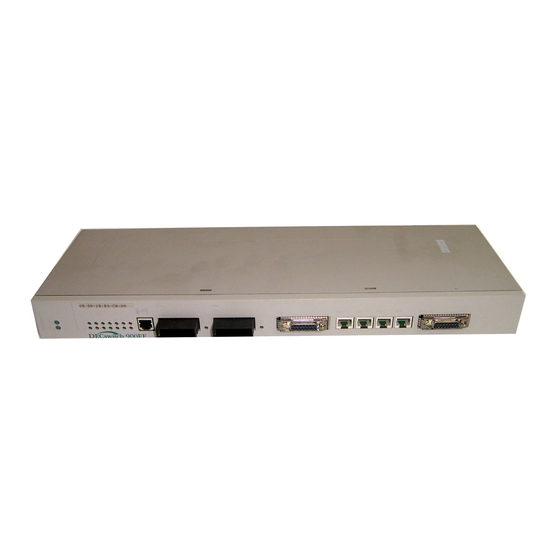
Front Panel Features Front Panel Features The following table describes the DECswitch 900EF front panel features shown in Figure 1-1. Table 1-1: Front Panel LEDs and Connectors Item Icon Name Description Power LED On = the module has power. Module OK On = the module passed self- test. -
Page 30: Front Panel Leds And Connectors
Front Panel Features Figure 1-1: Front Panel LEDs and Connectors NPG-9548-95F 1-10 Product Introduction... -
Page 31: Front Panel Leds And Connectors
Front Panel Features Table 1-2: Front Panel LEDs and Connectors Item Name Description Optical Bypass Allows you to connect an OBR Relay (OBR) device (not supplied) to (6-pin MJ) maintain connectivity of the connector FDDI ring in the absence of power or during fault conditions in a station. -
Page 32: Back Panel Features
Back Panel Features Back Panel Features The features on the back panel (Figure 1-2) of the DECswitch 900EF are listed in Table 1-3. Table 1-3: Back Panel Feature Descriptions Item Name Description Locking tab Locks the module into a DEChub 900 backplane or into a Dechub ONE docking station. - Page 33 Back Panel Features Figure 1-2: Back Panel Layout Product Introduction 1-13...
-
Page 35: Installing The Module
Installing the Module Overview Introduction This chapter describes how to install the DECswitch 900EF in a DEChub 900 MultiSwitch. To install a module in a DEChub ONE or DEChub ONE-MX docking station refer to the DEChub ONE Installation manual, the DEChub ONE-MX Installation manual or the DECswitch 900ET Quick Start card. - Page 36 Installing the Module in a DEChub 900 Installing the Module in a DEChub 900 The DECswitch 900EF hot-swap feature allows you to install the module into the DEChub 900 without turning off power. Seating the module initiates the module’s powerup sequence if enough power is available.
-
Page 37: Task 1: Compare The Power Ratings
Task 1: Compare the Power Ratings Task 1: Compare the Power Ratings Compare the module’s power ratings (1) with the values shown in the Hub Manager Status display (2) (see Figure 2-1). If any of the module's power requirements exceed the values shown in the status display, add another power supply (see the DEChub 900 MultiSwitch Owner’s Manual). -
Page 38: Task 2: Seat The Module Into The Dechub 900
Task 2: Seat the Module into the DEChub 900 Task 2: Seat the Module into the DEChub 900 To seat the module, perform the following steps (see Figure 2-2). Step Action Place the module’s mounting tab into a mounting slot (1) on the DEChub 900. -
Page 39: Task 3: Verify Initial Led Operation
After the module completes self-test, the Module OK LED lights and remains lit. Then the Hub Manager status display shows: DECswitch 900EF NOTE Refer to Appendix A, Problem Solving, if the LEDs do not operate as described. Figure 2-3: LED Location... -
Page 40: Task 4: Connect The Port Cables
Task 4: Connect the Port Cables Task 4: Connect the Port Cables Depending on your network configuration requirements, connect the appropriate FDDI cables, AUI Ethernet cables, and UTP/STP cables. See your network manager if you are not sure which cables to connect. NOTE All cables should be installed, tested, and tagged at the site, prior to this installation. -
Page 41: Task 4 (Cont.): Connect The Fddi Cables
Task 4 (Cont.): Connect the FDDI Cables Task 4 (Cont.): Connect the FDDI Cables To connect the FDDI cables, complete the following steps (see Figure 2-4). Step Action Remove the protective caps from the module’s FDDI connector and from the FDDI cable plug. Align the keyway (1) on the FDDI cable plug with the key on the module’s FDDI connector. -
Page 42: Task 4 (Cont.): Connect The Aui Ethernet Cables
Task 4 (Cont.): Connect the AUI Ethernet Cables Task 4 (Cont.): Connect the AUI Ethernet Cables To connect the AUI Ethernet cable, complete the following steps (see Figure 2-5). Step Action Push the module’s AUI connector slide latch up (1) to the unlocked position. -
Page 43: Task 4 (Cont.): Connecting The Utp/Stp Cable
Task 4 (Cont.): Connecting the UTP/STP Cable Task 4 (Cont.): Connecting the UTP/STP Cable The DECswitch 900EF Router module uses straight-through 10BaseT (8-pin MJ) port connectors. Select the appropriate UTP/STP cable type (crossover or straight-through) to ensure that the module’s transmit/receive signals connect correctly to the transmitter/receiver of the connected device. - Page 44 Task 4 (Cont.): Connecting the UTP/STP Cable To connect the UTP/STP cables, complete the following steps (see Figure 2-6). Step Action Align the release tab on the cable plug (1) with the keyway on the module’s 10BaseT port connector. Insert the plug into the connector (2), ensuring that the release tab snaps into the locked position.
-
Page 45: Installing The Setup Port Cable
Chapter 3 Installing the Setup Port Cable Overview Introduction This chapter describes how to connect the DECswitch 900EF module to the setup port on a DEChub 900 or the DEChub ONE docking station. In this chapter Topic Page Signaling Standards... -
Page 46: Signaling Standards
Signaling Standards Signaling Standards Signals from the DEChub 900 Hub Manager setup port and from the DEChub ONE docking station setup port conform to the EIA-232D signaling standard at 9600 baud. To the user, the port appears as a data terminal equipment (DTE) device. The DEChub 900 Hub Manager setup port is compatible with devices that use the EIA-423 signaling standard. -
Page 47: Setup Port Device Cabling
Setup Port Device Cabling Setup Port Device Cabling The setup port (see Figure 3-1) on the DEChub 900 MultiSwitch or the DEChub ONE docking station can be connected to a setup port device (a terminal or personal computer), using the following cables and adapters: If the setup port device is ... -
Page 48: Connecting The Setup Port
Connecting the Setup Port Connecting the Setup Port To connect the setup port on the DECswitch 900EF module, complete the following steps: Step Action Ensure that the transmit and receive baud rates on the setup port device are set to 9600 baud. - Page 49 Connecting the Setup Port Figure 3-1: Device, Cable and Connector Identification After all cables are connected, go to one of the following chapters. Go to Configure the module in a DEChub ONE Chapter 4 Configure the module in a DEChub 900 Chapter 5 Installing the Setup Port Cable 3-5...
-
Page 51: Setting Up And Configuring The Module In A Dechub One
DEChub ONE Overview Introduction This chapter describes how to setup and configure your DECswitch 900EF when it is installed in a standalone unit DEChub ONE docking station. For DEChub ONE installation procedures refer to the DEChub ONE Installation manual. For DEChub... -
Page 52: Accessing The Setup Port
Accessing the Setup Port Accessing the Setup Port The setup port provides menus that allow you to access the DECswitch 900EF. This setup menu allows you to minimally setup the module for basic connectivity. Examples of the setup screen displays are provided in this chapter to aid in the description of the setup port and to display the options that are available. -
Page 53: Using Menus To Setup The Module
Using Menus to Setup the Module Using Menus to Setup the Module This section describes the options that are available from the DECswitch 900EF INSTALLATION MENU when the module is installed in the DEChub ONE or DEChub ONE-MX docking station. -
Page 54: Reset With Factory Defaults
Memory (NVRAM) parameters to be initialized to factory default values followed by a module reset. (If you need to reboot the module and retain the current settings, choose option [2] from the DECswitch 900EF INSTALLATION MENU.) Allow approximately 1 minute for the module to reboot and complete self-test. -
Page 55: Reset With Current Settings
Allow approximately 1 minute for the module to restart. The following example shows the dialog associated with this option. Enter selection: DECswitch 900EF ======================================================================= RESET WITH CURRENT SETTINGS This selection will reset your system with the current configuration settings. -
Page 56: Show Current Settings
The Port 4 using front panel UTP port will change to reflect the current configuration of ports 1 and 4. The following example shows the display associated with this option: Enter selection : 3 DECswitch 900EF ======================================================================= DECswitch 900EF, 6-Ethernet/FDDI Switch, HW=v1/2,RO=v0.4,SW=v1.60 SysUpTime : 6days 00:03:18 18 resets SNMP Read/Write Community : whitney96 SNMP Trap Addresses : 16.7.88.156... -
Page 57: Configure Ip
[4] Configure IP [4] Configure IP This option provides you with IP configuration selections. The following examples show this option’s menus. Enter selection : 4 DECswitch 900EF ======================================================================= IP CONFIGURATION Set SNMP Read/Write Community Add SNMP Trap Addresses Delete SNMP Trap Addresses... -
Page 58: Set Snmp Read/Write Community
The following example shows this option’s dialog associated with this option. Enter selection : 1 DECswitch 900EF ======================================================================= SET SNMP READ/WRITE COMMUNITY Format: The format for a community name is a string,... -
Page 59: Add Snmp Trap Addresses
[4] Configure IP [2] Add SNMP Trap Addresses This option prompts you to enter IP addresses to which the DECswitch 900EF module sends SNMP traps. You can enter up to eight trap addresses. If one or more SNMP trap addresses were previously configured, the screen displays those addresses. -
Page 60: Delete Snmp Trap Addresses
IP address, where each octet of the address is represented as a decimal value, separated by a decimal point (.), for example 16.20.54.156. The following example shows the dialog associated with this option. Enter selection : 3 DECswitch 900EF ======================================================================= DELETE SNMP TRAP ADDRESSES Format:... -
Page 61: Set In-Band Interface Ip Address
(.), for example 16.20.54.156. The factory default setting is no in-band address. The following example shows the dialog associated with this option. Enter selection : 4 DECswitch 900EF ======================================================================= IN-BAND INTERFACE IP ADDRESS CONFIGURATION Format:... -
Page 62: Set Out-Of-Band Interface Ip Address
OBM port as an alternative to normal in-band management. To enable out- of-band management, you need to assign an OBM IP address and select an OBM port speed from the DECswitch 900EF Installation MENU. The following example shows the dialog associated with this option. -
Page 63: Enable/Disable Bootp
The factory default setting is DISABLED. If BootP is enabled, the word DISABLED shown in the following dialog is replaced with the word ENABLED. The following example shows the dialog associated with this option. Enter selection : 6 DECswitch 900EF ======================================================================= ENABLE/DISABLE BOOTP BOOTP is the IP bootstrap protocol. -
Page 64: Dump Error Log
Up to four error log dumps can be stored, and the most recent dump is displayed first. Firmware upgrades are also recorded in the error log. The following example shows the display associated with this option: Enter selection : 5 DECswitch 900EF ======================================================================= DUMP ERROR LOG CURRENT RESET COUNT: 45... -
Page 65: Downline Upgrade
If you need to assign an IP address to the module, complete the following steps: Step Action Select Configure IP (option4) from the DECswitch 900EF INSTALLATION MENU. Select Set In-Band Interface IP Address (option 4) from the IP Configuration menu. -
Page 66: Using The Dlu Process
Do not turn off power to the unit or perform any action that can cause the unit to lose power during Stage 3 of the DLU process. When you select this option from the DECswitch 900EF INSTALLATION MENU, the initial setup screen display appears. This screen identifies the option and alerts the user not to interrupt power during the downline load. -
Page 67: Initiaizing The Process
[6] Downline Upgrade Initializing the Process To initiate the DLU process, complete the following steps: Step Action Example Press Return <Return> a. If the file is in the default TFTP DEFBA160.BIN directory, enter the firmware image file <Return> name and press Return. (The TFTP load host conventions specify the format of the firmware image file name). -
Page 68: The Dlu Process Stages
[6] Downline Upgrade The DLU Process Stages The DLU process consists of four stages: Stage Description Transferring the image to the module’s temporary storage buffer Verifying the image Writing the new image into nonvolatile flash memory Module reset and self-test Table 4-1 explains what happens during each stage of the DLU process: Table 4-1: DLU Process Description Stage... - Page 69 [6] Downline Upgrade Stage Description The module verifies that the firmware image is correct. This stage normally takes 10 seconds to complete. The following states indicate that this stage is in progress: • Module status – functional. • Module can respond to management requests. •...
-
Page 70: If The Process Does Not Complete
[6] Downline Upgrade Stage Description The module resets, runs self-test, and then begins executing the new firmware image. This stage normally takes 1 minute to complete. The following states indicate that this stage is in progress: • Module status – not functional or manageable. •... -
Page 71: When The Dlu Process Is Complete
The Module OK LED turns on. • The module becomes fully operational. • The screen displays the DECswitch 900EF Installation Menu. Verifying the Upgrade After the DLU process has completed, you can verify the firmware upgrade by completing the following steps:... -
Page 72: Out-Of-Band Port Configuration
9600. The OBM port speed that you select must match the speed of your OBM device. The following example shows the dialog associated with this option. Enter selection : 1 DECswitch 900EF ==================================================================== SET OUT-OF-BAND (OBM) PORT SPEED [1] 2400 baud... -
Page 73: Module-Specific Options
When selected, the option allows you to set FDDI port configuration, set Ethernet configuration, and configure the IPX switch. The following example shows the dialog associated with this option. Enter selection : 8 DECswitch 900EF ========================================================= MODULE-SPECIFIC OPTIONS [1] Set FDDI Configuration... -
Page 74: Set Fddi Configuration
DEChub ONE-MX. This screen indicates the current station configuration. Enter selection : 1 DECswitch 900EF ====================================================================== DECswitch 900EF FDDI PORT CONFIGURATION MENU [1] Front Panel: A, B Docking Station: none [2] Front Panel: None Docking Station: A, B... -
Page 75: Set Fddi Configuration (Cont.)
DEChub ONE. Enter selection : 1 DECswitch 900EF ====================================================================== DECswitch 900EF FDDI PORT CONFIGURATION MENU [1] Front Panel: A, B [2] Front Panel: M, S [3] Return to Previous Menu Current configuration: Front Panel : A, B ====================================================================== Enter selection : [2] <Return>... -
Page 76: Set Ethernet Configuration
[8] Module-Specific Options [2] Set Ethernet Configuration This option allows you to set Ethernet configuration in standalone mode. This selection allows you to toggle the connection of port 4 between the module’s front panel and the docking station’s AUI port. When port 4 is connected to the AUI of a DEChub ONE docking station, note that the Network Activity LED corresponding to that port changes to yellow. -
Page 77: Configure Ipx Switch
(IPX) interconnects LANs to allow communication between client and server. When the IPX switch is enabled, the DECswitch 900EF translates raw 802.3 frames to SNAP encapsulated FDDI frames with a protocol type 81-37. When disabled, IPX frames are translated without SNAP encapsulation. The current state of the IPX switch can be viewed by selecting option [3] Show Current Settings in the DECswitch 900EF INSTALLATION MENU. -
Page 79: Configuring The Module In A Dechub 900
Chapter 5 Configuring the Module in a DEChub 900 Overview Introduction This chapter describes how to configure your DECswitch 900EF when it resides in a DEChub 900 MultiSwitch. In this chapter Topic Page DEChub 900 MultiSwitch Installation Menu Using Menus to Setup the Module Reset with Factory Defaults Reset with Current Settings‘... -
Page 80: Dechub 900 Multiswitch Installation Menu
DEChub 900 MultiSwitch Installation Menu DEChub 900 MultiSwitch Installation Menu The following screen is an example of the DEChub 900 MultiSwitch INSTALLATION MENU. To access the module’s setup screen, you must choose option [9] Start Redirect Mode. DEChub 900 MultiSwitch ============================================================= DEChub 900 MultiSwitch INSTALLATION MENU [1] Reset with Factory Defaults... -
Page 81: Start Redirect Mode
After you choose the Start Redirect Mode option from the DECswitch 900EF INSTALLATION MENU, the screen display prompts you for a slot number (8) as shown in the following example. -
Page 82: Using Menus To Setup The Module
Using Menus to Setup the Module Using Menus to Setup the Module This section describes the options that are available from the DECswitch 900EF INSTALLATION MENU when the module is installed in the DEChub 900 MultiSwitch. When your module is installed in the DEChub 900, the slot number where the module is installed appears at the top of the menu. -
Page 83: Reset With Factory Defaults
Memory (NVRAM) parameters to be initialized to factory default values followed by a module reset. If you need to reboot the module and retain the current settings, choose option [2] from the DECswitch 900EF Installation MENU. Allow approximately 1 minute for the module to reboot and complete self-test. -
Page 84: Reset With Current Settings
Allow approximately 1 minute for the module to restart. The following example shows the dialog associated with this option. Enter selection: DECswitch 900EF - slot 3 ======================================================================= RESET WITH CURRENT SETTINGS This selection will reset your system with the current configuration settings. -
Page 85: Show Current Settings
This option shows the module’s current settings. If the module is being configured for the first time, some fields will be blank. The following example shows the display associated with this option: Enter selection : 3 DECswitch 900EF - slot 3 ======================================================================= DECswitch 900EF, 6-Ethernet/FDDI Switch, HW=v1/2,RO=v0.4,SW=v1.6.0 SysUpTime... -
Page 86: Configure Ip
[4] Configure IP This option provides you with IP configuration selections. The following examples show this option’s menus. Enter selection : 4 DECswitch 900EF - slot 3 ========================================================= IP CONFIGURATION [1] Set SNMP Read/Write Community [2] Add SNMP Trap Addresses... -
Page 87: Set Snmp Read/Write Community
The following example shows this option’s dialog (user response is shown in boldface type): Enter selection : 1 DECswitch 900EF - slot 3 ==================================================================== SET SNMP READ/WRITE COMMUNITY Format:The format for a community name is a string, consisting of four to thirty-one printable ASCII characters, that describes the relationship between an SNMP agent and one or more SNMP managers. -
Page 88: Add Snmp Trap Addresses
[4] Configure IP [2] Add SNMP Trap Addresses This option prompts you to enter IP addresses to which the DECswitch 900EF module sends SNMP traps. You can enter up to eight trap addresses. If one or more SNMP trap addresses were previously configured, the screen displays those addresses. -
Page 89: Delete Snmp Trap Addresses
The following example shows the dialog associated with this option: Enter selection : 3 DECswitch 900EF - slot 3 ======================================================================= DELETE SNMP TRAP ADDRESSES Format: The standard 4 octet dotted decimal notation in which each octet of the address is represented as a decimal value, separated by a ’.’... -
Page 90: Set In-Band Interface Ip Address
The factory default setting is no in-band address. The following example shows the dialog associated with this option. Enter selection : 4 DECswitch 900EF - slot 3 ======================================================================= IN-BAND INTERFACE IP ADDRESS CONFIGURATION Format: The standard 4 octet dotted decimal notation in which each octet of the address is represented as a decimal value, separated by a ’.’... -
Page 91: Set Out-Of-Band Interface Ip Address
OBM port as an alternative to normal in-band management. To enable out- of-band management, you need to assign an OBM IP address and select an OBM port speed from the DECswitch 900EF Installation MENU. The following example shows the dialog associated with this option. -
Page 92: Enable/Disable Bootp
ENABLED. The following example shows the dialog associated with this option: Enter selection : 6 DECswitch 900EF - slot 3 ======================================================================= ENABLE / DISABLE BOOTP BOOTP is the IP bootstrap protocol. -
Page 93: Dump Error Log
Firmware upgrades are also recorded in the error log. The following example shows the display associated with this option: Enter selection : 5 DECswitch 900EF - slot 3 ======================================================================= DUMP ERROR LOG CURRENT RESET COUNT: 45... -
Page 94: Downline Upgrade
If you need to assign an IP address to the module, complete the following steps: Step Action Select Configure IP (option4) from the DECswitch 900EF INSTALLATION MENU. Select Set In-Band Interface IP Address (option 4) from the IP Configuration menu. -
Page 95: Using The Dlu Process
Do not turn off power to the unit or perform any action that can cause the unit to lose power during Stage 3 of the DLU process. When you select this option from the DECswitch 900EF INSTALLATION MENU, the initial setup screen display appears. This screen identifies the option and alerts the user not to interrupt power during the downline load. -
Page 96: Initiaizing The Process
[6] Downline Upgrade Initializing the Process To initiate the DLU process, complete the following steps: Step Action Example Press Return <Return> a. If the file is in the default TFTP directory, DEFBA160.BIN enter the firmware image file name and press <Return>... -
Page 97: The Dlu Process Stages
[6] Downline Upgrade The DLU Process Stages The DLU process consists of four stages: Stage Description Transferring the image to the module’s temporary storage buffer Verifying the image Writing the new image into nonvolatile flash memory Module reset and self-test Table 5-1 explains what happens during each stage of the DLU process: Configuring the Module in a DEChub 900 5-19... -
Page 98: Dlu Process Description
• Module status – functional and manageable. • Module can respond to management requests. • LED display – normal operation. • Hub Manager display – DECswitch 900EF • Setup screen – DLU process started! ....When the series of dots ends, the screen displays the following message: Transfer complete. - Page 99 • Module can respond to management requests. • LED display – normal operation. • Hub Manager display – DECswitch 900EF The DLU process transfers the new image from the module’s temporary storage buffer to the nonvolatile flash memory, overwriting the old image.
-
Page 100: If The Process Does Not Complete
— The Module OK LED is off. — The Port State LEDs flash indicating various subroutines are running (standard self-test pattern). • Hub Manager display – DECswitch 900EF unknown This message is normal. If the Process Does not Complete If the process does not complete, take one of the following actions:... -
Page 101: When The Dlu Process Is Complete
DECswitch 900EF INSTALLATION MENU. Press <Return>. Verify that the correct version was loaded. The screen displays the following text. DECswitch 900EF ======================================================================= DECswitch 900EF, 6-Ethernet/FDDI Switch, HW=v1/2,RO=v0.4,SW=v1.60 SysUpTime : 6days 00:03:18 18 resets SNMP Read/Write Community : whitney96 SNMP Trap Addresses : 16.7.88.156... -
Page 102: Module-Specific Options
Run Extended Diagnostics • Return to Main Menu The following example shows the dialog associated with this option: Enter selection : 7 DECswitch 900EF - slot 3 ========================================================= MODULE-SPECIFIC OPTIONS [1] Configure IPX Switch [2] Run Extended Diagnostics [3] Return to Main Menu... -
Page 103: Configure Ipx Switch
Protocol eXchange (IPX) interconnects LANs to allow communication between client and server. When the IPX switch is enabled, the DECswitch 900EF translates raw 802.3 frames to SNAP encapsulated FDDI frames with a protocol type 81-37. When disabled, IPX frames are translated without SNAP encapsulation. The current state of the IPX switch can be viewed by selecting option [3] Show Current Settings in the DECswitch 900EF INSTALLATION MENU. -
Page 104: Run Extended Diagnostics
[7] Module-Specific Options [2] Run Extended Diagnostics This option allows you to run certain diagnostics tests if you suspect that the module is faulty. The extended diagnostics test is the Ethernet backplane loopback test. All other tests run as part of the normal powerup self-test. CAUTION This action deletes all configured settings and replaces them with factory default values. - Page 105 The following example shows the dialog associated with this option: Enter selection : 2 DECswitch 900EF - slot 3 ========================================================= * * * * * * * * * * * * * * * * * * * * * * * * * * * * * * * * * * * *...
- Page 106 MENU. Display the DECswitch 900EF INSTALLATION MENU as described in the section titled ([9] Start Redirect Mode). Error log entries Select option [5] Dump Error Log in the DECswitch 900EF INSTALLATION MENU. This action dumps the most recent entry in the error log, if there are any entries. If...
-
Page 107: Removing The Module
Overview Introduction This chapter describes how to remove the DECswitch 900EF from a DEChub 900 MultiSwitch. If you need instructions on how to remove the DECswitch 900EF from a standalone module, refer to either the DEChub ONE Installation manual or the DEChub ONE-MX Installation manual. -
Page 108: Removing The Cables
Removing the Cables Removing the Cables WARNING Some fiber optic equipment can emit laser or infrared light that can injure your eyes. Never look into an optical fiber or connector port. Always assume the cable is connected to a light source. To remove cables from the module, complete the step in the following table that is appropriate for your type of cable (see Figure 6-1). -
Page 109: Unseating The Module
Unseating the Module Unseating the Module To unseat the module from the DEChub 900, complete the following steps (see Figure 6-2). Step Action Lift the release lever (1) located at the top of the DEChub 900 slot. While holding up the release lever (2), pivot the module back on its bottom mounting tab (3). -
Page 111: A Problem Solving
Appendix A Problem Solving Overview Introduction This appendix describes how to diagnose and solve problems with the module using the LED displays. In this appendix Topic Page LED Descriptions Problem Solving Using LEDs Problem Solving A-1... -
Page 112: Led Descriptions
LED Descriptions LED Descriptions The module’s LEDs provide dynamic indications of the status of the module. The LEDs can be in various states (on, off, or blinking), and can change color (green or yellow) depending on the operational status of the module or the level of activity on the network. -
Page 113: Led States
LED Descriptions Table A-1 shows the states that are possible for each of the module’s LEDs. Table A-1: LED States Blinking Name (Green) (Yellow) Power No power to Module module. receiving power. Module Self-test Passed self- N/A. Non-fatal failed (if test failure. -
Page 114: Fddi Phy Leds
LED Descriptions The FDDI Phy LEDs (see Table A-2) indicate the status of the connection between the module and the FDDI network. Table A-2: FDDI PHY LEDs Blinking Green Yellow Green Yellow Green / Name Color Yellow Ready Good Link Dis- Illegal or Stand-... -
Page 115: Problem Solving Using Leds
Problem Solving Using LEDs Problem Solving Using LEDs When diagnosing a problem with the module, note that the problem is often indicated by the combined states of the module LEDs. Table A-3 lists the typical combined states of the LEDs for various error conditions that can occur during initial installation of the device, along with probable causes and corrective actions to take. - Page 116 Problem Solving Using LEDs Table A-3: Typical Combined States of LEDs. Symptom Probable Corrective Action Cause Power LED is The module is Check the power status on the Hub off. not receiving Manager status display. +5Vdc. If the Hub Manager status display indicates that power is available for this module, press the release lever and reseat or remove the module.
- Page 117 Problem Solving Using LEDs Symptom Probable Corrective Action Cause Port State LED Port failure. Either replace the module or contact is on yellow. your service representative to correct the problem. Port State LED None — normal operation. is blinking corresponding green.
-
Page 119: B Connector And Pin Assignments
Appendix B Connector and Pin Assignments Overview Introduction This appendix shows the pin assignments of the connectors, cables, and adapters that are part of, or can be used with, the module. In this appendix Topic Page Connector Assignments Internal and External Crossover Configurations Connector and Pin Assignments B-1... -
Page 120: Connector Assignments
Connector Assignments Connector Assignments Optical Bypass Relay (6-pin MJ) Connector The Optical Bypass Relay (OBR) feature on the module maintains FDDI dual-ring integrity if the module fails or if the power to the module is turned off. Figure B-1 shows the OBR 6-pin Modular Jack (Shielded RJ12) connector and its pin assignments. -
Page 121: 10Baset (8-Pin Mj) Port Connector
Connector Assignments 10BaseT (8-pin MJ) Port Connector Figure B-2 shows the 8-pin MJ (straight-through) connector and its pin assignments. Table B-2: 10BaseT (8-pin MJ) Connector Pin Assignments Pin No. Assignment Unused Unused Unused Unused Figure B-2: 10BaseT (8-pin MJ) Connector NOTE All 10BaseT port connectors on the module are straight-through connections. -
Page 122: Aui (15-Pin D-Sub) Port Connector
Connector Assignments AUI (15-pin D-Sub) Port Connector Figure B-3 shows the shielded MJ8 Twisted Pair 15-pin AUI connector and its pin assignments. Table B-3: AUI 15-Pin Port Connector Pin Assignments Pin No. Assignment Ground Ground Power rtn Ground Ground Power 12V Ground Figure B-3: AUI 15-Pin Port Connector B-4 Connector and Pin Assignments... -
Page 123: H8571-J Adapter
Connector Assignments H8571-J Adapter This section shows the H8571-J adapter (6-pin MMJ to 9-pin D-Sub connector) and its pin assignments as shown in Figure B-4. Figure B-4: H8571-J Adapter H8575-A Adapter This section shows the H8575-A adapter (6-pin MMJ connector to 25-pin D-Sub connector) and its pin assignments as shown in Figure B-5. -
Page 124: Internal And External Crossover Configurations
Internal and External Crossover Configurations Internal and External Crossover Configurations A crossover function must be implemented in every twisted-pair link. The crossover function (internal or external) allows the transmitter of one device to connect to the receiver of the device at the other end of the twisted-pair link. Figure B-6 shows straight-through (1) and crossover cables (2) for connecting crossover (3) and straight-through (4) types of devices. -
Page 125: C Product Specifications
Appendix C Product Specifications Overview Introduction This appendix lists the operating specifications and the acoustical specifications for the DECswitch 900EF Router. In this appendix Topic Page Operating Specifications Acoustical Specifications Product Specifications C-1... - Page 126 Product Specifications Product Specifications Table C-1 lists the product specifications for the module. Table C-1: Product Specifications Parameter Specification Environment 5° C to 50° C (41 ° F to 122 ° F) Operating Temperature Relative Humidity 10% to 95% noncondensing Altitude •...
- Page 127 Table C-2: Connector Specifications Module Connectors DECswitch 900EF has: one Dual Attachment Station (DAS) FDDI port multimode optics (ANSI MIC), one shielded 6-pin MJ (OBR), two 15-pin D-Sub (AUI ports), and four shielded 8-pin MJ (10BaseT ports) with straight through connectors.
-
Page 128: Acoustical Specifications
Level LpAm, dBA (bystander positions) Idle/Operate: Idle/Operate: DECswitch 900EF DEFBA-MA DECswitch 900EF & DEChub ONE DEFBA-MA + DEHUA DECSwitch 900EF & DEChub ONE-MX DEFBA-MA + DEF1H Current values for specific configurations are available from Digital Equipment representatives. 1 B = 10 dBA. -
Page 129: Aktuelle Werte Für Spezielle Produkt
L LpAm, dBA (Zuschauerpositione Leerlauf/Betrieb: Leerlauf/Betrieb: DECswitch 900EF DEFBA-MA DECswitch 900EF & DEChub ONE DEFBA-MA + DEHUA DECSwitch 900EF & DEChub ONE-MX DEFBA-MA + DEF1H Aktuelle Werte für spezielle Ausrüstungsstufen sind über die Digital Equipment Vertretungen äerhltlich. 1 B = 10 dBA. -
Page 131: D Accessing And Configuring Rmon Groups
Appendix D Accessing and Configuring RMON Groups Overview Introduction This appendix describes how to access the four RMON groups and how to configure the Alarms and Events groups. In this appendix Topic Page Why is RMON? Groups Supported How to Access RMON Groups Accessing and Configuring RMON Groups D-1... -
Page 132: What Is Rmon
What is RMON? What is RMON? RMON is a Remote Network Monitoring Management Information Base (RMON MIB). RMON gathers a wide variety of statistical information about network operation. A typical network consists of multiple network segments with one RMON agent connected to each segment. RMON gathers this information by examining each packet passed on a network segment. -
Page 133: Groups Supported
Groups Supported Groups Supported The four RMON groups supported by this module are Statistics, History, Alarms, and Events. The following table defines these four groups: This group... Allows you to... Statistics Obtain an array of operational statistics including: • Packets •... -
Page 134: How To Access Rmon Groups
MultiChassis Manager as follows: Step Action Run the clearVISN MultiChassis Manager. Double-click on the DECswitch 900EF module. (The summary screen displays the module’s summary.) Click on the RMON button to display the Statistics screen. Click on the HISTORY button on the Statistics screen. -
Page 135: Alarm And Event Table Entries
How to Access RMON Groups The RMON Alarms and Events MIB objects and eventCommunity support up to 32 characters. MIB object eventDescription, alarmOwner, and eventOwner support up to 127 characters. The maximum number of entries that can be placed in the alarmTable is 20. -
Page 136: Alarm Table Entry Fields
How to Access RMON Groups Table D-1: Alarm Table Entry Fields Alarm Table Entry Fields Definition alarmIndex An index that uniquely identifies an entry (see note below). alarmInterval The interval, in seconds, over which the data is sampled and compared with the rising and falling threshold. -
Page 137: Event Table Entries
How to Access RMON Groups Table D-2: Event Table Entries Event Table Definition Entry Fields eventIndex An index that uniquely identifies an entry (see note below). eventDescription A comment describing this event. eventType The type of notification that will occur when the threshold is being reached. -
Page 138: How Traps Work
How to Access RMON Groups How Traps Work SNMP-managed devices are able to send trap messages to network management stations. You configure the IP addresses of NMS “trap sinks” that are to receive the RMON trap messages. For additional information on traps, refer to RFC 1215: M. Rose, "A Convention for Defining Traps for use with the SNMP", 03/27/1991.
Need help?
Do you have a question about the DECswitch 900EF and is the answer not in the manual?
Questions and answers