Digital Equipment DECswitch 900EF Installation And Configuration Manual
Hide thumbs
Also See for DECswitch 900EF:
- Installation and configuration manual (130 pages) ,
- Installation and configuration manual (138 pages)
Table of Contents

Subscribe to Our Youtube Channel
Related Manuals for Digital Equipment DECswitch 900EF


Summary of Contents for Digital Equipment DECswitch 900EF
- Page 1 DECswitch 900EF Router Installation and Configuration Order Number: EK-DEFBA-DN. A01 July 1995 This manual describes how to install and configure the DECswitch 900EF Router. Revision/Update Information: This is a new manual.
- Page 2 July 1995 The information in this document is subject to change without notice and should not be construed as a commitment by Digital Equipment Corporation. Digital Equipment Corporation assumes no responsibility for any errors that may appear in this document.
-
Page 3: Table Of Contents
Contents Preface Safety 1 Product Introduction Overview ..........................1–1 What is the DECswitch 900EF Router? ................1–2 Features ..........................1–3 Front Panel Features......................1–8 Back Panel Features ......................1–10 2 Installing the Module Overview ..........................2–1 Installing the Module in a DEChub 900................2–2 Task 1: Compare the Power Ratings ..................2–3 Task 2: Seat the Module into the DEChub 900 ..............2–4... - Page 4 3 Installing the Setup Port Cable Overview ..........................3–1 Signaling Standards......................3–2 Setup Port Device Cabling ....................3–3 Connecting the Setup Port....................3–4 4 Setting Up and Configuring the Module in a DEChub ONE Overview ..........................4–1 Accessing the Setup Port....................... 4–2 Using Menus to Setup the Module..................
- Page 5 B Connector and Pin Assignments Overview ..........................B–1 Connector Assignments ......................B–2 Internal and External Crossover Configurations..............B–7 C Product Specifications Overview ..........................C–1 Operating Specifications ....................... C–2 Acoustical Specifications....................... C–4...
- Page 6 Figures Figure 1-1 Front Panel LEDs and Connectors ..............1–9 Figure 1-2 Back Panel Layout ....................1–11 Figure 3-1 Device, Cable and Connector Identification............3–5 Figure 6-1 Cable Removal ....................6–3 Figure 6-2 Unseat the Module ..................... 6–4 Figure B-1 Optical Bypass Relay Connector................ B–2 Figure B-2 10BaseT Port Connector ..................
- Page 7 Tables Table 1-1 Front Panel Feature Descriptions ................1–8 Table 1-2 Back Panel Feature Descriptions ...............1–10 Table A-1. Module LED States .................... A–3 Table A-2 FDDI PHY LED States ..................A–4 Table A-3 Problem Solving Using the LEDs................ A–5 Table B-1. Optical Bypass Relay Connector Pin Assignments..........B–2 Table B-2 10BaseT Port Connector Pin Assignments ............
- Page 8 viii...
-
Page 9: Overview
Preface Overview About this Manual This manual describes how to install the DECswitch 900EF Router in a DEChub 900 MultiSwitch. This manual also describes how to configure the DECswitch 900EF Router software to operate in either a DEChub 900 MultiSwitch or as a standalone module in a DEChub ONE docking station. - Page 10 Organization This manual is organized as follows: Section Description Provides an overview of the DECswitch 900EF Router, describes its features, and lists front and back panel features. Provides instructions for installing the module in a DEChub 900 MultiSwitch. Provides instructions for installing the setup port cable.
- Page 11 Associated Documents The following documents provide information relating to the module. To order any of the following documents, refer to the directions on page xiii. Title and Order Number Description Bridging Configuration Describes bridging methods, operational Guide features of bridging, configuration methods AA-QL29A-TE and basic configurations, and monitoring of bridging software.
- Page 12 Associated Documents (Cont.) Title and Order Number Description HUBwatch Use Describes how to use the HUBwatch network AA-PW4BE-TE management software. Provides information for installing and configuring HUBwatch for Open VMS and or DEC OSF/1 (Digital UNIX) operating system environment. HUBwatch for Windows Describes how to use the HUBwatch network management software in an MS-Windows AA-Q3S3C-TE...
- Page 13 A&SG Business Manager c/o Digital’s local subsidiary or approved distributor Internal orders should be placed through U.S. Software Supply Business (SSB), Digital Equipment Corporation, 10 Cotton Rd. Nashua, NH. 03063-1260 *Any prepaid order from Puerto Rico must be placed with the Local Digital Subsidiary: 809–754–7575...
- Page 15 Safety Overview Any warning or caution that appears in this manual is defined as follows: WARNING Contains information to prevent personal injury. CAUTION Contains information to prevent damage to equipment. VORSICHT Enthält Informationen, die beachtet werden müssen, um den Benutzer vor Schaden zu bewahren.
- Page 16 The cautions that must be observed for the hardware described in this manual are listed below in English, German, French, and Spanish. WARNING To prevent personal injury or equipment damage, do not insert telecommunications cabling into the Optical Bypass Relay connector.
- Page 17 WARNING Some fiber optic equipment can emit laser or infrared light that can injure your eyes. Never look into an optical fiber or connector port. Always assume the cable is connected to a light source. VORSICHT Bestimmte Lichtleitergeräte können für die Augen gefährliches Laser- oder Infrarotlicht abstrahlen.
- Page 18 CAUTION This action deletes all configured settings and replaces them with factory default values. All configuration settings will be lost. ACHTUNG Bei diesem Vorgang werden alle Konfigurationseinstellungen gelöscht und die Werkseinstellungen wieder eingesetzt. Alle Konfigurationsdaten gehen verloren. ATTENTION Cette action supprime tous les paramètres de configuration et les remplace par des valeurs prédéfinies.
- Page 19 Chapter Product Introduction Overview Introduction This chapter describes the DECswitch 900EF Router product and its features. In this chapter Topic Page What is the DECswitch 900EF Router? Features Front Panel Features Back Panel Features 1-10 Product Introduction 1–1...
-
Page 20: What Is The Decswitch 900Ef Router
What is the DECswitch 900EF Router? What is the DECswitch 900EF Router? The DECswitch 900EF Router (also referred to in this manual as the module) provides multiprotocol routing and switching. This module interconnects networks that have both routable and nonroutable protocols. -
Page 21: Features
Features Features Your DECswitch 900EF Router module includes the following features. Hot Swap The module’s hot swap capability allows you to install or remove the module from a DEChub 900 without turning off the power. Configuration and Management The following configuration and management options are available: •... - Page 22 Features Routing Protocols The following routing protocols are supported: • IP. The IP routing protocols are as follows: –– OSPF (Open Shortest Path First) –– RIP (Routing Information Protocol) –– EGP (Exterior Gateway Protocol) –– IS-IS (Integrated Intermediate System to Intermediate System) ––...
- Page 23 Features Bridging The following bridging options are supported: • Spanning tree loop detection protocol IEEE 802.1d. • Ability to enable or disable spanning tree algorithm on individual switch ports on a per-port basis. • High-speed local traffic filtering and forwarding. •...
- Page 24 Features FDDI/Ethernet FDDI and Ethernet support is as follows: • One FDDI dual attachment station (DAS) port and six 802.3/Ethernet LAN ports. • Translation between FDDI and IEEE 802.3/Ethernet frame formats for direct, transparent connections; translation of AppleTalk®1 and AppleTalk 2 AARP packets; handling of raw IEEE 802.3 Novell® IPX packets.
- Page 25 Features SNMP Built-in SNMP agent support for the following RFCs is provided: • SNMP management (RFC-1157) • Management Information Base - MIB II (RFC-1213) • Bridge MIB (RFC-1493) • FDDI MIB (RFC-1512) • Ethernet MIB (RFC-1398) Manageability using any generic SNMP management application that supports the MIBs listed above.
-
Page 26: Front Panel Features
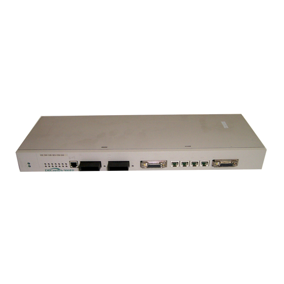
Front Panel Features Front Panel Features The LED indicators and connectors on the front panel (Figure 1-1) of the DECswitch 900EF Router are described in Table 1-1. Table 1-1 Front Panel Feature Descriptions Item Name Description Power LED Indicates the module has power. -
Page 27: Figure 1-1 Front Panel Leds And Connectors
Front Panel Features Figure 1-1 Front Panel LEDs and Connectors Product Introduction 1–9... -
Page 28: Back Panel Features
Back Panel Features Back Panel Features The features on the back panel (Figure 1-2) of the DECswitch 900EF Router are listed in Table 1-2. Table 1-2 Back Panel Feature Descriptions Item Name Description Locking tab Locks the module into the DEChub 900 and engages the power switch. -
Page 29: Figure 1-2 Back Panel Layout
Back Panel Features Figure 1-2 Back Panel Layout Product Introduction 1–11... -
Page 31: Installing The Module
Installing the Module Overview Introduction This chapter describes how to install the DECswitch 900EF Router in a DEChub 900 MultiSwitch. To install a module in a DEChub ONE docking station refer to the DEChub ONE Installation manual. In this chapter... -
Page 32: Installing The Module In A Dechub 900
Installing the Module in a DEChub 900 Installing the Module in a DEChub 900 The DECswitch 900EF Router hot-swap feature allows you to install the module into the DEChub 900 without turning off power. Seating the module initiates the module's powerup sequence if enough power is available. -
Page 33: Task 1: Compare The Power Ratings
Task 1: Compare the Power Ratings Task 1: Compare the Power Ratings Compare the module’s power ratings (1) with the values shown in the Hub Manager Status display (2) (see Figure 2-1). If the power values on the module’s manufacturing label do not exceed the values shown in the Hub Manager status display, go to Task 2. -
Page 34: Task 2: Seat The Module Into The Dechub 900
Task 2: Seat the Module into the DEChub 900 Task 2: Seat the Module into the DEChub 900 To seat the module, perform the following steps (refer to Figure 2-2). Step Action Place the module’s mounting tab into a mounting slot (1) on the DEChub 900. - Page 35 Task 2: Seat the Module into the DEChub 900 Figure 2-2 Seating the Module Installing the Module 2–5...
-
Page 36: Task 3: Verify Initial Led Operation
Task 3: Verify Initial LED Operation Task 3: Verify Initial LED Operation Verify that the module's Power LED and the Module OK LED light within 1 minute (See Figure 2-3). The LEDs light in the following two occurrences: Occurrance Description The Power LED lights when power is applied to the DEChub 900, then the module performs a self-test. -
Page 37: Task 4: Connect The Cables
Task 4: Connect the Cables Task 4: Connect the Cables Depending on your network configuration requirements, connect the appropriate FDDI cables, AUI cables and UTP/STP cables. See your network manager if you are not sure which cables to connect. _____________________________ Note ____________________________ All cables should be installed, tested, and tagged at the site, prior to this installation. - Page 38 Task 4 (Cont.): Connect the FDDI Cable Task 4 (Cont.): Connect the FDDI Cable To connect the FDDI cable, complete the following steps (see Figure 2-4). Step Action Remove the protective caps from the module's FDDI connector and from the FDDI cable plug. Align the keyway on the FDDI cable plug with the key on the module's FDDI connector.
- Page 39 Task 4 (Cont.): Connect the AUI Cable Task 4 (Cont.): Connect the AUI Cable To connect the AUI cable, complete the following steps (see Figure 2-5). Step Action Push the module's AUI connector slide latch up (1) to the unlocked position. Insert the AUI cable plug into the AUI connector.
- Page 40 Task 4 (Cont.): Connecting the UTP/STP Cable Task 4 (Cont.): Connecting the UTP/STP Cable The DECswitch 900EF Router module uses straight-through 10BaseT 8-pin MJ) port connectors. Select the appropriate UTP/STP cable type (crossover or straight-through) to ensure that the module's transmit/receive signals connect correctly to the transmitter/receiver of the connected device.
- Page 41 Task 4 (Cont.): Connecting the UTP/STP Cable To connect the UTP/STP cables, complete the following steps (see Figure 2-6). Step Action Align the release tab on the cable plug (1) with the keyway on the module's 10BaseT port connector. Insert the plug into the connector (2), ensuring that the release tab snaps into the locked position.
-
Page 43: Installing The Setup Port Cable
Chapter Installing the Setup Port Cable Overview Introduction This chapter describes how to connect the DECswitch 900EF Router module to the setup port on a DEChub 900 MultiSwitch or a DEChub ONE docking station. In this chapter Topic Page Signaling Standards... -
Page 44: Signaling Standards
Signaling Standards Signaling Standards Signals from the DEChub 900 Hub setup port and from the DEChub ONE docking station setup port conform to the EIA-232D signaling standard at 9600 baud. To the user, the port appears as a data terminal equipment (DTE) device. -
Page 45: Setup Port Device Cabling
Setup Port Device Cabling Setup Port Device Cabling The setup port (see Figure 3-1) on the DEChub 900 MultiSwitch or the DEChub ONE docking station can be connected to a setup port device (a terminal or personal computer), using the following cables and adapters: If the setup port device is Use this With this adapter... -
Page 46: Connecting The Setup Port
Connecting the Setup Port Connecting the Setup Port To connect the setup port on the DECswitch 900EF module, complete the following steps: Step Action Ensure that the transmit and receive baud rates on the setup port device are set to 9600 baud. -
Page 47: Figure 3-1 Device, Cable And Connector Identification
Connecting the Setup Port Figure 3-1 Device, Cable and Connector Identification After all cables are connected, go to one of the following sections. Go to Configure the Router in a DEChub ONE Chapter 4 Configure the Router in a DEChub 900 Chapter 5 Installing the Setup Port Cable 3–5... -
Page 49: Setting Up And Configuring The Module In A Dechub One
Chapter Setting Up and Configuring the Module in a DEChub ONE Overview Introduction This chapter describes how to setup and configure your DECswitch 900EF Router when it is installed in a standalone unit DEChub ONE docking station. For DEChub ONE installation procedures refer to the DEChub ONE Installation manual. -
Page 50: Accessing The Setup Port
Boldface type in the screen display examples indicates user input. To access the setup menus, press the Return key on the setup port device until the DECswitch 900EF/MP INSTALLATION MENU appears. To configure the module using Go to the section titled... -
Page 51: Using Menus To Setup The Module
DEChub ONE docking station The following example shows the dialog associated with this option when the module is setup with factory defaults. DECswitch900EF/MP ============================================================= DECswitch 900EF/MP INSTALLATION MENU Restart with Factory Defaults Restart with Current Settings Show Current Settings IP Configuration... - Page 52 DECswitch900EF/MP ============================================================= DECswitch 900EF/MP INSTALLATION MENU * * * * * * * * * * * * * * * * * * * * * * * * * * * * * * * * * To fully manage this router telnet to one of its IP addresses or select item [3] below.
-
Page 53: Restart With Factory Defaults
If you selected Y, then the following additional information appears: About to Initialize CONFIG memory Configuration memory initialized System Restart ... Then the DECswitch 900EF/MP INSTALLATION MENU menu appears. Setting Up and Configuring the Module in a DEChub ONE 4–5... -
Page 54: Restart With Current Settings
Using Menus to Setup the Module [2] Restart with Current Settings This option restarts the module but leaves the module's configured nonvolatile configuration storage parameters at their current values. ______________________NOTE____________________________ Allow approximately 1 minute for the module to restart. _______________________________________________________ The following example shows the dialog associated with this option. -
Page 55: Show Current Settings
Using Menus to Setup the Module [3] Show Current Settings This option shows the module's current settings. If the module is being configured for the first time, some of the fields will be blank. The following example shows the dialog associated with this option. Enter selection : 3 DECswitch900EF/MP ====================================================================... -
Page 56: Ip Configuration
Using Menus to Setup the Module [4] IP Configuration The IP Configuration option provides you with 5 selections. The following example shows the dialog associated with this option. Enter selection: 4 DECswitch900EF/MP =================================================================== IP CONFIGURATION * * * * * * * * * * * * * * * * * * * * * * * * * * * * * * * * * Configuration will not take effect until module is restarted. - Page 57 Using Menus to Setup the Module [4] IP Configuration (Cont.) [1] Set SNMP Read/Write Community This option prompts you to enter the module's SNMP read/write community name. The following example shows the dialog associated with this option. Enter selection: DECswitch900EF/MP ==================================================================== SET SNMP READ/WRITE COMMUNITY Format: The format for a community name is a string,...
- Page 58 Using Menus to Setup the Module [4] IP Configuration (Cont.) [2] Set In-Band Interface IP Address This option prompts you to change or enter the IP address and subnet mask for the in-band interface. You can only configure one in-band interface at a time.
- Page 59 To enable out-of-band management, you need to assign an OBM IP address and select an OBM port speed from the DECswitch 900EF/MP INSTALLATION MENU. The module does not need to be configured with a subnet mask for SNMP and Telnet communications with management stations located on the same subnet as the module.
- Page 60 Using Menus to Setup the Module [4] IP Configuration (Cont.) [4] Set Default Gateway This option sets the default gateway, if necessary, for the in-band interface. This is the address of a router that the module will use when communicating to a remote host. The default gateway address must be an address in the same subnet as your in-band address.
-
Page 61: Out-Of-Band Port Configuration
Using Menus to Setup the Module [5] Out-of-Band Port Configuration This option lets you set the out-of-band port speed and enable or disable Request To Send (RTS). ______________________NOTE____________________________ The port speeds at both ends of the communications link must be identical. - Page 62 Using Menus to Setup the Module [5] Out-of-Band Port Configuration (Cont.) [1] Set Port Speed This option lets you select the out-of-band port speed. The factory default for this option is 9600 baud. The OBM port speed that you select must match the speed of your OBM device.
- Page 63 Using Menus to Setup the Module [5] Out-of-Band Port Configuration (Cont.) [2] Enable/Disable RTS This option allows you to enable or disable Request To Send (RTS). The factory default for this option is Disabled. If the RTS is disabled, the following dialog appears on the screen. Enter selection: 2 DECswitch900EF/MP ===================================================================...
-
Page 64: Go To Local Console
Go to Local Console Go to Local Console You must configure the module before it is operational. There are two options that you can use to do this. The first option runs a quick configuration interactive question and answer dialog. This (qconfig) method allows fast configuration of interfaces, basic bridging, and IP and IPX configuration. - Page 65 Go to Local Console Then the DECswitch 900EF/MP INSTALLATION MENU displays. DECswitch900EF/MP ============================================================= DECswitch 900EF/MP INSTALLATION MENU * * * * * * * * * * * * * * * * * * * * * * * * * * * * * * * * * To fully manage this router telnet to one of its IP addresses or select item [3] below.
- Page 66 DECswitch900EF/MP ============================================================= DECswitch 900EF/MP INSTALLATION MENU * * * * * * * * * * * * * * * * * * * * * * * * * * * * * * * * * To fully manage this router telnet to one of its IP addresses or select item [3] below.
- Page 67 This section describes commands that are unique to the DECswitch 900EF Router. Other CONFIG commands needed to configure the DECswitch 900EF Router can be found in the Bridge Router Software System Software Guide. You can use two methods to configure the module: Telnet (using commands) and OBM (via a menu).
- Page 68 Go to Local Console Configuring Ethernet Port 3 Connection This section describes how to configure the Ethernet Port 3 configuration for front (connector on the front of the Module) or back (connector on the DEChub ONE). Step Action At the Config> prompt enter: net 3 At the ETH config>...
- Page 69 Go to Local Console Configuring OBM This section describes how to set the OBM IP address, speed, and enable RTS. After entering talk 6, at the Config> prompt you can set the following three OBM parameters as follows: Parameter Description Default set obm ip 16.40.156.20 Sets the out-of-band current IP-...
-
Page 71: Configuring The Module In A Dechub 900
Chapter Configuring the Module in a DEChub 900 Overview Introduction This chapter describes how to configure your DECswitch 900EF Router when it resides in a DEChub 900 MultiSwitch. In this chapter Topic Page Accessing the Setup Port DEChub 900 MultiSwitch Installation Menu Using Menus to Setup the Module Configuring the Module in a DEChub 900 5–1... -
Page 72: Accessing The Setup Port
Accessing the Setup Port Accessing the Setup Port Examples of the setup screen displays are provided in this section to aid in the description of the setup port and to display the options that are available. Because they are examples only, the displays can vary slightly from the actual screen displays on your setup port device. -
Page 73: Dechub 900 Multiswitch Installation Menu
DEChub 900 MultiSwitch Installation Menu DEChub 900 MultiSwitch Installation Menu The following screen is an example of the DEChub 900 MultiSwitch INSTALLATION MENU. To access the module’s set up screen, you must choose option [9] Start Redirect Mode. The following example shows the dialog associated with this option. DEChub 900 MultiSwitch ============================================================= DEChub 900 MultiSwitch INSTALLATION MENU... - Page 74 The Start Redirect Mode option redirects the DEChub 900 MultiSwitch Hub Manager set-up port to the set-up port of any network module (such as the DECswitch 900EF Router) that is installed into the DEChub 900 MultiSwitch. Choosing this option allows you to set-up or obtain the status of an installed network module by accessing the specified network module's installation menu.
-
Page 75: Using Menus To Setup The Module
900EF/MP INSTALLATION MENU when the module is installed in the DEChub 900 MultiSwitch. The following example shows the dialog associated with this option. DECswitch900EF/MP - slot 8 ============================================================= DECswitch 900EF/MP INSTALLATION MENU Restart with Factory Defaults Restart with Current Settings Show Current Settings IP Configuration... - Page 76 DECswitch900EF/MP - slot 8 ============================================================= DECswitch 900EF/MP INSTALLATION MENU * * * * * * * * * * * * * * * * * * * * * * * * * * * * * * * * * To fully manage this router telnet to one of its IP addresses.
- Page 77 Using Menus to Setup the Module [1] Restart with Factory Defaults This option restarts the module, causing the module's configured nonvolatile configuration storage parameters to be initialized to factory default values. (To retain current values, use option [2] Restart with Current Settings.) Allow approximately one minute for the module to restart and complete self-test.
- Page 78 Using Menus to Setup the Module [2] Restart with Current Settings This option restarts the module but leaves the module's configured nonvolatile configuration storage parameters at their current values. ______________________NOTE____________________________ Allow approximately 1 minute for the module to Restart. _______________________________________________________ The following example shows the dialog associated with this option.
- Page 79 Using Menus to Setup the Module [3] Show Current Settings This option shows the module's current settings. If the module is being configured for the first time, some of the fields will be blank. The following example shows the screen display associated with this option.
- Page 80 Using Menus to Setup the Module [4] IP Configuration The IP Configuration option provides you with 5 selections. The following example shows the dialog associated with this option. Enter selection: 4 DECswitch900EF/MP - slot 8 =================================================================== IP CONFIGURATION * * * * * * * * * * * * * * * * * * * * * * * * * * * * * * * * * Configuration will not take effect until module is restarted.
- Page 81 Using Menus to Setup the Module [4] IP Configuration (Cont.) [1] Set SNMP Read/Write Community This option prompts you to enter the module's read/write community name. The following example shows the dialog associated with this option. Enter selection: DECswitch900EF/MP - slot 8 ==================================================================== SET SNMP READ/WRITE COMMUNITY Format: The format for a community name is a string,...
- Page 82 Using Menus to Setup the Module [4] IP Configuration (Cont.) [2] Set In-Band Interface IP Address This option prompts you to change or enter the IP address and subnet mask for the in-band interface. The module does not need to be configured with a subnet mask for SNMP communications with management stations located on the same subnet as the module.
- Page 83 Using Menus to Setup the Module [4] IP Configuration (Cont.) [3] Set Out-of-Band Interface IP Address This option prompts you to change or enter the IP address and subnet mask for the out-of-band interface. The module does not need to be configured with a subnet mask for SNMP communications with management stations located on the same subnet as the module.
- Page 84 Using Menus to Setup the Module [4] IP Configuration (Cont.) [4] Set Default Gateway This option sets the default gateway, if necessary. This is the address of a router that the module will use when communicating to a remote host. The default gateway address must be in the same subnet as your in-band address.
-
Page 85: Removing The Module
Chapter Removing the Module Overview Introduction This chapter describes how to remove the DECswitch 900EF Router from a DEChub 900 MultiSwitch. To remove the DECswitch 900EF Router from a standalone module, refer to the DEChub ONE Installation manual. In this chapter... -
Page 86: Removing The Cables
Removing the Cables Removing the Cables To remove cables from the module, complete the steps in the following table that is appropriate for your type of cable (see Figure 6-1). ________________________ WARNING ____________________________ Some fiber optic equipment can emit laser or infrared light that can injure your eyes. -
Page 87: Figure 6-1 Cable Removal
Removing the Cables Figure 6-1 Cable Removal Removing the Module 6–3... -
Page 88: Unseating The Module
Unseating the Module Unseating the Module To unseat the module from the DEChub 900, complete the following steps (see Figure 6-2). Step Description Lift the release lever (1) located at the top of the DEChub 900 slot. While holding up the release lever (2), pivot the module back on its bottom mounting tab (3). -
Page 89: A Problem Solving Overview
Appendix Problem Solving Overview Introduction This appendix describes how to diagnose and solve problems with the module using the LED displays. In this chapter Topic Page LED Descriptions Problem Solving Using LEDs Problem Solving A–1... -
Page 90: Led Descriptions
LED Descriptions LED Descriptions The module's LEDs provide dynamic indications of the status of the module. The LEDs can be in various states (on, off, or flashing), and can change color (green or yellow) depending on the operational status of the module or the level of activity on the network. -
Page 91: Table A-1. Module Led States
LED Descriptions Table A-1 shows the states that are possible for each of the module's LEDs. Table A-1. Module LED States LED Name On (Green) On (Yellow) Flashing Power No power to Module receiving N/A. N/A. module. power. Self-test failed (if Passed self-test N/A. -
Page 92: Table A-2 Fddi Phy Led States
LED Descriptions The FDDI Phy LEDs (see Table A-2) indicate the status of the connection between the module and the FDDI network. Table A-2 FDDI PHY LED States Flashing No Color Green Yellow Green Yellow Green / Name Yellow Ready to Good Link Error Disabled... -
Page 93: Problem Solving Using Leds
Problem Solving Using LEDs Problem Solving Using LEDs When diagnosing a problem with the module, note that the problem is often indicated by the combined states of the module LEDs. Table A-3 lists the typical combined states of the LEDs for various error conditions that can occur during initial installation of the device, along with probable causes and corrective actions to take. - Page 94 Problem Solving Using LEDs Symptom Probable Cause Corrective Action Module OK LED is off. Self-test in Wait for self-test to progress. complete. Self-test failed. If the LED does not light within 60 seconds, lift the release lever momentarily to repeat the self-test. If self-test fails again, replace the module.
- Page 95 Problem Solving Using LEDs Symptom Probable Cause Corrective Action Port State LED is off. 1. Connection is bad Correct the cable (loose, or incorrect connection. cable). 2. Port not None -- normal connected. operation. Port State LED is on Port failure. Either replace the yellow.
-
Page 97: B Connector And Pin Assignments
Appendix Connector and Pin Assignments Overview Introduction This appendix shows the pin assignments of the connectors, cables, and adapters that are part of, or can be used with, the module. In this chapter Topic Page Connector Assignments Internal and External Crossover Configurations Connector and Pin Assignments B–1... -
Page 98: Connector Assignments
Connector Assignments Connector Assignments Optical Bypass Relay (6-pin MJ) Connector The Optical Bypass Relay (OBR) feature on the module maintains FDDI dual-ring integrity if the module fails or if the power to the module is turned off. The following illustration shows the OBR 6-pin Modular Jack (Shielded RJ12) connector and its pin assignments. -
Page 99: Figure B-2 10Baset Port Connector
Connector Assignments 10BaseT (8-pin MJ) Port Connector This section shows the 8-pin MJ (straight-through) connector and its pin assignments. Table B-2 10BaseT Port Connector Pin Assignments Assignment Unused Unused Unused Unused Figure B-2 10BaseT Port Connector ______________________NOTE____________________________ All 10BaseT port connectors on the module are straight-through connections. -
Page 100: Table B-3 Aui Port Connector Pin Assignments
Connector Assignments AUI (15-pin D-Sub) Port Connector This section shows the 15-pin AUI connector and its pin assignments. Table B-3 AUI Port Connector Pin Assignments Ports Ground Ground Power rtn Ground Ground Power 12V Ground B–4 Connector and Pin Assignments... -
Page 101: Figure B-3 Aui Port Connector
Connector Assignments Figure B-3 AUI Port Connector Connector and Pin Assignments B–5... -
Page 102: Figure B-4 H8571-J Adapter
Connector Assignments H8571-J Adapter This section shows the H8571-J adapter (6-pin MMJ to 9-pin D-Sub connector) and its pin assignments. Figure B-4 H8571-J Adapter H8575-A Adapter This section shows the H8575-A adapter (6-pin MMJ connector to 25-pin D-Sub connector) and its pin assignments. Figure B-5 H8575-A Adapter ______________________NOTE____________________________ EOS/ESD protection devices are not shown in the illustration. -
Page 103: Internal And External Crossover Configurations
The following illustration shows straight-through (1) and crossover cables (2) for connecting crossover (3) and straight-through (4) types of devices. The DECswitch 900EF Router uses straight-through connectors. Figure B-6 Crossover Configurations If screened cabling is required, use BN26M. -
Page 105: C Product Specifications
Appendix Product Specifications Overview Introduction This appendix lists the operating specifications and the acoustical specifications for the DECswitch 900EF Router. In this chapter Topic Page Operating Specifications Acoustical Specifications Product Specifications C–1... -
Page 106: Operating Specifications
0.1 A, 12Vdc 1.5 A, 15Vdc Connectors: DECswitch 900EF has: one Dual Attachment Station (DAS) FDDI port multimode optics (ANSI MIC), one shielded 6-pin MJ (OBR), two 15-pin D-Sub (AUI ports), and four shielded 8-pin MJ (10BaseT ports) with straight through connectors. -
Page 107: Table C-2 Physical Specifications And Certification
Operating Specifications Table C-2 Physical Specifications and Certification Parameter Specifications Physical: Height 4.45 cm (1.75 in) Width 15.25 cm (6 in); 25.40 cm (10.0 in) with a DEChub ONE docking station. Depth 15.25 cm (6 in); 25.40 cm. Weight 1.8 kg (4 lb) Certification: CE, CSA, FCC,T-V, UL, VCCI... -
Page 108: Acoustical Specifications
Sound Power Level Sound Pressure Level LpAm, dBA (bystander positions) Idle/Operate: Idle/Operate: DECswitch 900EF Router DEFBA-MA DECswitch 900EF & DEChub ONE DEFBA-MA + DEHUA Current values for specific configurations are available from Digital Equipment representatives. 1 B = 10 dBA. -
Page 109: Table C-4 Aktuelle Werte Für Spezielle Produkt
Table C-4 Aktuelle Werte für spezielle Produkt Produkt Schalleistungspege Schalldruckpegel LpAm (Zuschauerpositionen) Leerlauf/Betrieb: Leerlauf/Betrieb: DECswitch 900EF Router DEFBA-MA DECswitch 900EF & DEChub ONE DEFBA-MA + DEHUA Aktuelle Werte für spezielle Ausrüstungsstufen sind über die Digital Equipment Vertretungenäerh-ltlich. 1 B = 10 dBA. - Page 110 Acoustical Specifications C–6 Product Specifications...
Need help?
Do you have a question about the DECswitch 900EF and is the answer not in the manual?
Questions and answers