
Related Manuals for VibroSystM ZOOM ZPU-5000

Summary of Contents for VibroSystM ZOOM ZPU-5000
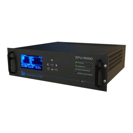
- Page 1 ™ -5000 Acquisition and Processing Unit with ZOOM Version 7.4 User’s Manual P/N: 9483-06M1A-240...
- Page 2 VibroSystM Inc. and the third parties. This manual is provided solely for guidance. VibrosystM Inc. takes no responsibility or liability for any damage caused by accidents, improper installation or misuse. Liability is limited to the repair and/or replacement of defective products.
- Page 3 Safety Precautions Warning - Danger Caution Although most instruments and accessories are normally used at • non-hazardous voltage levels, hazardous conditions may still be present in some situations. This product is intended to be used by qualified operators and maintenance personnel who •...
-
Page 4: Table Of Contents
TABLE OF CONTENTS 1. OVERVIEW OF THE ZPU-5000 1.1 Supported software and types of measurements 1.2 Features and functions 1.3 ZPU-5000 components 1.3.1 ZPU-5000 unit - Front view 1.3.1.1 Front panel display 1.3.1.2 Keypad 1.3.1.3 Front panel LED indicators 1.3.1.4 USB port 1.3.2 ZPU-5000 unit - Rear view 1.3.2.1 Analog I/O modules 1.3.2.2 Control module... - Page 5 3.3.2 View air gap parameters 3.4 Overview of the options in the Menu mode 3.4.1 Import a configuration 3.4.2 Export a configuration 3.4.3 View information about VibroSystM 3.4.4 View the ZPU-5000 system information 3.4.5 View the modules information 3.4.6 Export alarms 3.4.7 View or acknowledge alarms...
- Page 6 ZPU-5000 Acquisition and Processing Unit with ZOOM Version 7.4 - User’s Manual...
-
Page 7: Overview Of The Zpu-5000
OVERVIEW OF THE ZPU-5000 The ZPU-5000 is a multi-channel acquisition and processing unit designed for monitoring large rotating units such as turbo-generators, hydroelectric generators, and large motors. Each ZPU-5000 unit can simultaneously monitor up to 16 high-speed parameters. The modular construction of the ZPU-5000 unit supports up to eight two-channel analog input/output modules. Each analog input/output module accomplishes several functions: Applies a selected process on each input signal;... -
Page 8: Features And Functions
The internal memory of a ZPU-5000 unit also supports the firmware and tables needed by four ZOOM data acquisition and communication services: ZOOM ZPU5000 ZOOM ThermaWatch® Stator Available plug-ins ZOOM Modbus® ZOOM OPC ZPU-5000 units collect data in one of four measurement types: Pole Sampling Possible Measurements... -
Page 9: Zpu-5000 Unit - Front View
1.3.1 ZPU-5000 unit - Front view The front panel user interface includes a front panel display, a seven-button keypad, four LED indicators, and one USB port. 1.3.1.1 Front panel display The front panel display shows messages on a 256 x 128 dot grid. In Menu mode, the display shows configuration information. -
Page 10: Usb Port
• Turns Yellow upon startup, then turns Green as long as the system is operating correctly. • Green indicates that the ZPU-5000 is properly connected to its ZOOM ZPU5000 service through the ZOOM server. • Turns Orange when a system component malfunction occurs, such as a ZOOM plug-in interruption, a network connection error, or other malfunction type. -
Page 11: Zpu-5000 Unit - Rear View
1.3.2 ZPU-5000 unit - Rear view Terminal block connectors with removable female screw terminal connectors allow permanent wiring of cable harnesses with the advantage of quick connect/disconnect. Format Location Recommended Wire Size 3-pos. ZPU-5000 Power Input 1,5 mm [16 AWG] (300 V rating) 1-pos. -
Page 12: Communication Module
• Synchronization inputs; • Synchronization output; • Alarm inhibit; • External trigger; • Acquisition trigger; • Rotation; • “System OK” relay driver; • “Channels OK” relay driver; • Two relay drivers for optional configurations (configurable in the ZOOM software). 1.3.2.3 Communication module This module enables communication to various instruments: •... -
Page 13: Installation
ZPU-5000 units are usually delivered pre-installed and pre-cabled inside a cabinet. ZPU 5000 units can also be ordered separately as an addition to an existing installation. When ZPU-5000 units are added to a standard cabinet from VibroSystM, pre-wired harnesses are available. 2.1 Installing the ZPU-5000 in a cabinet or enclosure The following guidelines will help you plan your equipment cabinet configuration: •... - Page 14 A 3-position panel header and a mating connector are provided for power input. * Note: Newer models of ZPU-5000 units are protected by a single fuse, and are offered in various AC and DC power input ranges. ZPU-5000 Acquisition and Processing Unit with ZOOM Version 7.4 - User’s Manual...
-
Page 15: Installing Modules In The Zpu-5000 Unit
2.1.2 Installing modules in the ZPU-5000 unit Modules of the correct type must be placed in the correct slots. Slot 9 is dedicated to the Control module, and slot 10 is dedicated to the Communication module. Slots 1 to 8 are reserved for Analog I/O modules and the location of each must match the ZPU-5000 Hardware Configuration form. -
Page 16: Dual-Channel Analog I/O Modules
2.2 Dual-channel analog I/O modules Dual-channel analog I/O modules convert input signals according to selected processes and generate corresponding analog signals. All analog I/O modules have the same pinout, but each module is factory-configured for a specific input source. Important Information The processed raw output does not correspond to the sensor’s signal: the frequency content of the •... -
Page 17: Analog I/O Module - Input
2.2.1 Analog I/O module - Input Each channel received an input signal on a 3-position panel header with a mating connector. Each module is factory-configured for a specific input source. 2.2.1.1 4 to 20 mA current input modules Module Input Range Maximum Processed Range (BW) AGM-4/20 4 to 20 mA... -
Page 18: Fiber Optic Accelerometer (Foa) Input Modules
2.2.1.2 Fiber optic accelerometer (FOA) input modules Maximum Processed Range (BW) Module Input Range Input Sensitivity Acceleration Velocity Displacement FIM-40-100 0 to 40 g Peak 100 mV/g 40 g Peak 100 mm/s Peak 2000 µm Peak to Peak (15 to 1000 Hz) (30 to 1000 Hz) (30 to 1000 Hz) FIM-40-100(LF) -
Page 19: Piezoelectric Accelerometer (Icp) Input Modules
2.2.1.3 Piezoelectric accelerometer (ICP) input modules Maximum Processed Range (BW) Module Input Range Input Sensitivity Acceleration Velocity Displacement ICPM-1.13-500 1.13 g Peak 500 mV/g 1.13 g Peak 28 mm/s Peak 2000 µm Peak-to-Peak (0.7 to 1000 Hz) (0.7 to 1000 Hz) (0.7 to 1000 Hz) ICPM-5.65-500 5.65 g Peak... -
Page 20: Voltage Input Modules
2.2.1.4 Voltage input modules Module Input Range Maximum Processed Range (BW) VIM 0/+5 0 to 5 V According to Measuring Chain (DC to 1000 Hz) VIM -5/+5 -5 to 5V According to Measuring Chain (DC to 1000 Hz) VIM 0/10 0 to 10 V According to Measuring Chain (DC to 1000 Hz) VIM -10/+10... -
Page 21: Analog I/O Module - Outputs
2.2.2 Analog I/O module - Outputs Each channel supports eight output signals on a 14-position panel header with a mating connector. Raw Out: Analog outputs that represent the processed raw signal from the sensor on the corresponding • input channel. Important Information Raw and Trend outputs (4/20 mA) do not require power from an external source. -
Page 22: Control Module
Relay Driver Outputs • Important Information Relay driver outputs require power from an external source. • - Output type: Bipolar FET, ± 30V / 25 mA max. isolated ground - Output state: Transistor OFF no alarm Transistor ON alarm detected 2.3 Control module The control module manages four types of signal: Synchro. -
Page 23: Synchro 1/Rev. Output
Synchro signal inputs (2 x); • Input type: pull up to 24Vdc; Control type: NPN open collector proximity switch. 24 Vdc output to power the synchronization probe(s). • 2.3.2 SYNCHRO 1/rev. output Use the signal from this output to view the synchro 1/rev. pulse on an instrument other than the ZPU-5000. Output type: NPN collector with resistor pull-up to 5 V •... - Page 24 2. External Trigger: An input used to start a sampling or pole measurement. The measurement type can be selected in the ZOOM Configuration software. Input type: 10 kΩ pull up resistor to 24 Vdc; • Control type: dry contact or electronic switch. •...
-
Page 25: Relay Driver Outputs
2.3.4 Relay driver outputs This set of outputs is used to drive relays and keep the user informed about system events such as System OK and Channels OK. The illustration below shows a configuration with multiple ZPU-5000 acquisition units. Note: Relay drivers 1 and 2 are available for optional configurations using the ZOOM software. -
Page 26: Communication Module
2.4 Communication module Wiring Connections 2.4.1 USB Port The USB port allows connection of a portable storage device to copy the configuration or to update the firmware. 2.4.2 Ethernet Port A 10/100 Mbps port for communication with the ZOOM software through a CAT6-E cable (recommended). 2.4.3 RS-485/422 Port The user can choose between half-duplex (RS-485) or full-duplex (RS-422) communication with TWS and RTU protocols directly in the ZOOM Configuration software. - Page 27 RS-485 in half duplex mode, typical connection. Note: Jumpers S3 and S4: ON Important Information 120 Ω termination resistor is only installed on the • LAST UNIT of a chain. RS-422 in full-duplex mode, typical connection. Note: Jumpers S3 and S4: OFF Important Information 120 Ω...
-
Page 28: Operation
OPERATION Once the unit has completed its boot-up sequence and starts running in Monitoring mode, press the MENU button to toggle between Monitoring and Menu modes. The Menu mode gives access to the configuration menu for reviewing or changing the unit’s configuration parameters. 3.1 Startup (boot-up sequence) When power is applied, the ZPU-5000 searches its internal memory for stored firmware and the last configuration information used. - Page 29 4. Square brackets around the ZPU-5000 network address indicate that the acquisition unit is not connected to the network yet. As the boot-up process continues, other screens are displayed to announce the update of the components in progress. 5. When the update of all plug-ins and firmware has completed, the ZPU-5000 starts.
-
Page 30: Using The Keypad
8. Finally, the ZPU-5000 starts normal operation, and the front panel display shows real-time information. Round brackets around the ZPU-5000 network address indicate that the acquisition unit is now connected to the network. The front panel LED indicators should now be: SYSTEM OK: Green CHANNELS OK: Green 3.2 Using the keypad... -
Page 31: Overview Of The Display In Monitoring Mode
3.3 Overview of the display in monitoring mode The illustration below illustrates a typical ZPU-5000 front panel display during normal operation. 1) The address allows quick validation of the connection to the network and the server. The address can be made up of 2 or 9 characters. -
Page 32: View Spectral Band Parameters
8) Indicates a channel name assigned by the user in the ZOOM Configuration software. The description may contain up to 32 characters, however only the first 28 characters are displayed. 9) Indicates the input parameter type associated with this sensor. 10) Indicates processing selected for the sensor, if any. -
Page 33: View Air Gap Parameters
3.3.2 View air gap parameters Pressing ENTER on an AGM-4/20 channel will display the sensor’s minimum air gap value, and if programmed, the maximum rotor pole variation over one turn. The AGM-4/20 acquisition module can be programmed to trigger two types of alarms on air gap measurements. -
Page 34: Overview Of The Options In The Menu Mode
3.4 Overview of the options in the Menu mode The menus are organized in a tree structure, with main options leading to sub-menus. The following are directions on how to browse through the menus and execute various commands after pressing on the Menu key. Use the tree structure as a reference. Important Information If access rights have been assigned, only users who have an Admin access code can access all the •... -
Page 35: Import A Configuration
3.4.1 Import a configuration Select Configuration → Import • To import a configuration, you will be prompted to insert a USB key. This USB key, previously prepared either on a VSM server or workstation with the ZOOM Configuration command File > Export or prepared on another ZPU-5000 unit with the Configuration →... -
Page 36: View Information About Vibrosystm
3.4.3 View information about VibroSystM Select Information → About VibroSystM • This screen displays VibroSystM contact information. 3.4.4 View the ZPU-5000 system information Select Information → System • This screen shows information about the ZPU-5000 unit. 3.4.5 View the modules information Select Information →... -
Page 37: Adjust The Front Panel Brightness
3.4.10 Adjust the front panel brightness Select Settings → Display → Brightness • This screen provides a way to change the brightness level. 3.4.11 Change the power saving option Select Settings → Display → Power Options • This menu allows setting a delay after which the front panel display turns off automatically to save power. By default, the display is always powered on. -
Page 38: Select The Network Or Standalone Mode
Operation Admin Guest Configuration → Import Configuration → Export Information → About VibroSystM Information → System Information → Modules Information → Alarms Information → System OK Detail Settings → Display Settings→... -
Page 39: View Or Delete Existing Access Codes Assigned To Users
Settings → Mode Settings → Access rights Maintenance → Export Logs Maintenance → Restart Unit Maintenance → Firmware The first four-digit access code must be assigned with an Admin access right (access to all the commands), after which various Guest users with restricted rights can be added. The sequence of commands to create a new access code and a selected access right is as follows: Select Settings →... -
Page 40: Restart The Unit
3.4.19 Restart the unit Important Information Before restarting the unit, read all warnings that appear on the front panel display. • Select Maintenance → Restart unit • Open this screen to restart the unit by pressing ENTER. 3.4.20 Uninstall the firmware Select Maintenance →... - Page 41 Caution Do not disconnect the ZPU-5000 during the update process. • 6. Once the operation is completed on a module, a message is displayed to confirm that the update was successful. If another module is installed, the updating program then continues with the next one. 7.
-
Page 42: Configuring The Zpu-5000 With Zoom Software
CONFIGURING THE ZPU-5000 WITH ZOOM SOFTWARE The properties of the ZPU-5000 unit, modules, and attached sensors can be edited through the ZOOM Configuration program. Read the contextual help supplied with the ZOOM software for more information. The two following sections are provided to explain how processing at module level. 4.1 Module firmware and spectral analysis processing The CIM-4/20, ICPM-1.13, FIM-40-100, ICPM-5.65-500, and FIM-40-100(LF) acquisition modules can be programmed with spectral analysis firmware designed for monitoring specific frequencies and protecting fixed... -
Page 43: Troubleshooting
If the acquisition unit receives power, verify the fuse in the fuse-holder (at the rear of the acquisition unit). • If the acquisition unit still fails to respond, contact VibroSystM for further assistance. • If the LED indicators and front panel display do not turn on, a major power supply or main component failure •... -
Page 44: Analog Input/Output Modules
NotOK(F): the firmware version is incorrect. See section 3.5 Firmware update to version 7.4 with a • prepared USB key NotOK(A/D): the A/D card is not working. Contact VibroSystM. • NotOK(V): the configuration version does not match the software version; •... -
Page 45: Ctrl-100 Module
5.5 CTRL-100 module Verify the LED indicator at the rear of the control module upon startup: The LED indicator should turn Green for 2 seconds, blink three times, then flash a short pulse each time the • ZPU-5000 receives the synchronization signal when the unit is in rotation. This confirms that the synchronization probe is present and operational. - Page 46 ZPU-5000 Acquisition and Processing Unit with ZOOM Version 7.4 - User’s Manual...
Need help?
Do you have a question about the ZOOM ZPU-5000 and is the answer not in the manual?
Questions and answers