Table of Contents
Advertisement
Quick Links
Advertisement
Table of Contents

Subscribe to Our Youtube Channel
Related Manuals for Soterix Medical MEGA-TMS

Summary of Contents for Soterix Medical MEGA-TMS
- Page 1 MEGA-TMS Operator’s Manual Version 1.0.5 ТМ063.04.001.00 (20.03.2020) US-edition...
- Page 2 Soterix Medical © 2021 1480 US 9 North, 204, Woodbridge, NJ, 07095, USA Phone: +1-888-990-8327 E-mail: contact@soterixmedical.com Internet: www.soterixmedical.com...
-
Page 3: Table Of Contents
Contents Introduction........................4 Indications for Use ......................5 Contraindications ......................5 Possible Side Effects ....................5 Warning and Precautions ...................6 Description ......................9 1.1. Main Specifications ..................9 Delivery Set ......................12 1.2. Structure and Operation ................14 1.3. Controls, Connectors and Indicators .............16 1.3.1. Controls, Connectors and Indicators of Stimulator .......16 1.3.2. -
Page 4: Introduction
Introduction Introduction This technical manual (hereinafter referred to as “manual”) is the combined document describing operation and servicing of MEGA-TMS magnetic stimulator (hereinafter re- ferred to as “stimulator”). This manual is the document which certifies the stimulator specifications guaranteed by the manufacturer. -
Page 5: Indications For Use
Indications for Use Indications for Use Stimulation of peripheral nerves for diagnostic purposes. Contraindications Although the magnetic stimulation in single pulse mode is a safe procedure, before the stimulation, each patient must be screened for contraindications. The absolute contraindications include implanted devices that are activated or controlled in any way by physiological signals (examples: cardiac demand pacemakers, implanted electronic devices, cochlear implants, pregnant women). -
Page 6: Warning And Precautions
MEGA-MS/Neuro-MS Magnetic Stimulator (Technical Manual) complain to shortness of breath, anxiety, sweating, dizziness, nausea, pallor, weak pulse, bradycardia, narrowing and blacking out of the visual field. It should be noted that patients who develop syncope under TMS often have experienced similar episodes in the past. 5. - Page 7 Warning and Precautions Before the stimulation, make sure, that there are no patient cables or electrodes connected to a patient and also metal parts contacting with a patient in impact area (within 5 cm and less from the coil) as far as the electromagnetic field can create the electrical current leaking through a patient.
- Page 8 MEGA-MS/Neuro-MS Magnetic Stimulator (Technical Manual) The use of accessories, spare parts and cables other than in delivery set may result in decreased EMC immunity and increased emissions of the equipment. The user must not install third-party software The general principles of safety regulations are stated in: •...
-
Page 9: Description
Description 1.1. Main Specifications Table 1. Main specifications of magnetic stimulator Parameters Values Stimulation Parameters Peak magnetic field at 100% output (depends on coil): 0 –1.5 T • monophasic (FEC-03-0100) 0 –1.8 T • monophasic (AFEC-03-0100) Duration of raise part of pulse: •... - Page 10 MEGA-MS/Neuro-MS Magnetic Stimulator (Technical Manual) Unit weight not more than 30 kg Operating Conditions Temperature + (10–35)°С Relative humidity from 30 to 85% (non-condensing) Atmospheric pressure from 70 to 106 kPa Transportation Conditions Temperature -25 to +60°C Humidity from 20 to 95% non-condensing Atmospheric pressure from 70 kPa...
- Page 11 As for safety, magnetic stimulator complies with AAMI/ANSI 60601- 1:2005/(R)2012 requirements, it is referred to class I and has BF type work parts complying with AAMI/ANSI ES 60601-1:2005/(R)2012 requirements.
-
Page 12: Delivery Set
The delivery set of the stimulator corresponds to Table 4 and Table 5. The figures in “Quantity, pcs.” column of Table 4 and Table 5 indicate: 1 — MEGA-TMS magnetic stimulator (configuration for single pulse stimulation (here- inafter referred to as “configuration 1”). - Page 13 NS059998.009 Holders: – K-8 coil holder (trolley/wall mounted) NS059998.004 Operating Documentation: MEGA-TMS technical manual TM063.01.001.001 Coils for magnetic stimulators “MEGA-TMS” and TM058.02.003.000 “MEGA-TMS” technical manual Package: – Cardboard package (set) MEGA-TMS unit package NS063901.001 Table 5. Additional Equipment, Accessories and Software Included in Delivery Set by Customer’s Request...
-
Page 14: Structure And Operation
MEGA-MS/Neuro-MS Magnetic Stimulator (Technical Manual) 1.2. Structure and Operation Depending on the selected configuration, MEGA-TMS magnetic stimulator can include one stimulator unit (hereinafter referred to as “stimulator”). Stimulator unit allows to generate single electromagnetic pulses of specified intensity. The block diagram of system with 1 stimulator unit intended for single stimulation is shown in Fig. - Page 15 Fig. 3. Monophasic waveform. The current flowing through the coil results in heating. The higher is the pulse intensity and stimulation frequency, the quicker is the heating of the operating surface of the coil. The contact with this heated surface can evoke hyperaemia or burn. To control the temperature, the coils are equipped with the temperature sensors.
-
Page 16: Controls, Connectors And Indicators
MEGA-MS/Neuro-MS Magnetic Stimulator (Technical Manual) 1.3. Controls, Connectors and Indicators 1.3.1. Controls, Connectors and Indicators of Stimulator Fig. 4. The front panel of stimulator. The front panel of stimulator contains: “Coil change” button combined with “High voltage” indicator. The “High voltage” indicator highlights yellow when the stimulator is switched on and up to 2800 V high voltage is supplied inside the stimulator. - Page 17 “Trigger” button. When stimulator is in “Armed” state, the single pressing of “Trigger” button activates the single stimulation. To perform continuous stimulation, press and hold “Trigger” button. The pulse is generated “Armed” state. continuously when stimulator reaches To stop the stimulation, release “Trigger” button. This button is duplicated with “Trigger”...
- Page 18 MEGA-MS/Neuro-MS Magnetic Stimulator (Technical Manual) To deliver the mains supply to the magnetic stimulator, turn “Mains power” switch to On (I) position. To disconnect from the mains supply, set the “Mains power” switch to Off (0) position. 10. USB connector. The connector is intended to attach the stimulator to the computer using USB cable.
-
Page 19: Controls, Connectors And Indicators Of Coil
1.3.2. Controls, Connectors and Indicators of Coil Fig. 6. Coil. The coil contains: HV connector into plug into stimulator unit. “Trigger” button combined with “Armed/Overheating” indicator. The indicator illuminates with: ‒ “red” – the coil is overheated; the stimulation is impossible; ‒... -
Page 20: Stimulator Menu
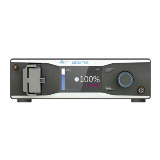
MEGA-MS/Neuro-MS Magnetic Stimulator (Technical Manual) 1.4. Stimulator Menu 1.4.1. Single Pulse Mode Fig. 7. The single pulse mode. The stimulator display in single pulse mode shows the following (Fig. 7): “Coil temperature” indicator. The “Coil temperature” indicator is a scale showing coil heating: •... - Page 21 “State” indicator shows the current state of stimulator: • “Disarmed” – the stimulator is powered and switched on, high voltage is not delivered, the stimulator cannot deliver pulses; • “Charging” – the stimulator is powered and switched on, high voltage is delivered, the capacitor is being charged, the stimulator cannot deliver pulses;...
-
Page 22: Setup Mode
MEGA-MS/Neuro-MS Magnetic Stimulator (Technical Manual) 1.4.2. Setup Mode To adjust the settings (Fig. 8), press On/Off button to exit the standby mode and hold simultaneously the “Stimulation parameters” knob. Fig. 8. “Settings” menu. The “Settings” menu is intended to customize the stimulator settings according to op- erational requirements. -
Page 23: Labeling
• Device info (Fig. 9) – when this item is selected, the device switches to “DEVICE INFORMATION” menu. It shows information on stimulator and coil if it is connected. Fig. 9. “Device information” menu. 1.5. Labeling Fig. 10. Labeling - attention: consult operational documentation. - work parts of BF type according to AAMI/ANSI ES 60601-1:2005/(R)2012. - Page 24 MEGA-MS/Neuro-MS Magnetic Stimulator (Technical Manual) Fig. 11. The GS1-128 barcode. 1 — identification key: GTIN; 2 — start digit; 3 — company number; 4 — article reference; 5 — check digit; 6 — serial number identifier; 7 — serial number. GTIN –...
-
Page 25: Assembly And Installation
Assembly and Installation 2.1. Requirements to Personnel Conducting Stimulator Assembly and Installation The stimulator should be installed by a person who is authorized by the manufacturer or the technical personnel of the medical institution which is going to use it. It is nec- essary to know that safety and quality of operation depend on the proper assembly of the magnetic stimulator. -
Page 26: Room Selection And Placement
MEGA-MS/Neuro-MS Magnetic Stimulator (Technical Manual) 2.2. Room Selection and Placement Before assembly and installation of stimulator, it is required to select a place for it, tak- ing into consideration power wiring and protective ground in a room, and also to read the following requirements and recommendations. - Page 27 Fig. 15. The block diagram of stimulator placement when connecting to digital EMG systems produced by other manufacturers. The following abbreviations are used in the figures: • EMG – electronic unit of digital EMG system; • MS – magnetic stimulator; •...
-
Page 28: Unpacking And Delivery Set Check
MEGA-MS/Neuro-MS Magnetic Stimulator (Technical Manual) must not touch simultaneously these parts and patient body. The computer equip- ment used with the stimulator should comply with AAMI/ANSI ES 60601-1:2005/(R)2012 requirements or be connected via the isolation transformer (specialized power supply unit – for notebook PC) that meets the above- mentioned requirements. -
Page 29: Assembly And Connection Of Stimulator
PC! Read carefully the related sec- tions of the user manual for the EMG device. Contact Soterix Medical for additional information. Placement of the units, performing of inter-unit connection and connection to the mains is carried out only when the “Mains power” switch of all units is switched off (“0”... - Page 30 MEGA-MS/Neuro-MS Magnetic Stimulator (Technical Manual) Fig. 16. The fixation of holder on the trolley. Fig. 17. The fixation of coil on the holder. 2.4.2.4 Position the stimulator unit(s) on trolley shelves according to recommenda- tions and secure them with the required fastenings (see chapter 4 of tech- nical manual for the trolley).
- Page 31 The coil connector should be fixed with locking plate (Fig. 18). Fig. 18. The coil connection to the stimulator. 2.4.2.6 Fix K-3/K-7 flexible arm for coil positioning on a trolley according to technical manual for the arm. If the trolley is not included to delivery set, the arm is fixed to any surface, for example the table or the bed.
- Page 32 MEGA-MS/Neuro-MS Magnetic Stimulator (Technical Manual) 2.4.2.9 If the stimulator is used together with desktop-based systems place the PC near the stimulator according to recommendations stated in p. 2.2 “Room Selection and Placement”. The position of PC depends on its type: •...
- Page 33 If the dialog box shown in Fig. 20 appears after stimulator connection to computer, press button, without inserting the electronic media. Fig. 20. “Found New Hardware Wizard” dialog box. “New hardware wizard” will perform the stimulator installation. On installation comple- tion the dialog box shown in Fig.
-
Page 34: Assembling Configuration For Single Pulse Stimulation
The stimulator is connected to the mains via the mains supply cable. The end cap is placed at HV connector located at the rear panel and is fixed with the locking plate. Fig. 22. MEGA-TMS stimulator assembling (configuration 1). MEGA-TMS stimulator unit. Mains supply cable. -
Page 35: Proper Use
Proper Use 3.1. Operation Order Before powering on the stimulator, perform the assembly and the connection of the units according to chapter 2 “Assembly and Installation”. All the units should be con- nected to the mains. Make sure that the units of the stimulator do not have any visible mechanical defects. If any issue arises during stimulator operation, the error code should appear on the stimulator display. - Page 36 MEGA-MS/Neuro-MS Magnetic Stimulator (Technical Manual) 2. Plug in the required coil to the stimulator output. Make sure that the high- voltage connector of the coil is plugged in firmly and the spring-lock is locked. If the connector is plugged in incorrectly, the HV connector may burn. “On/off”...
-
Page 37: Usb Control Mode
“On/Off” button. 10. On operation completion, switch off the stimulator using After that disconnect the coil and disinfect it according to recommendations stated in the technical manual for coils. 11. Turn “Mains power” switch on rear panel to Off (0) position. 3.3. -
Page 38: Acquisition Of Evoked Potentials
MEGA-MS/Neuro-MS Magnetic Stimulator (Technical Manual) Run Neuro-MEP.NET software by pressing icon. Neuro-MEP.NET is the software provided with Focus EMG device. Refer to the Focus EMG manual for additional information. 3.4. Acquisition of Evoked Potentials The acquisition of evoked responses to magnetic stimulation is done using the same techniques as for electrical stimulation. -
Page 39: Troubleshooting
3.5. Troubleshooting The possible troubles are listed in Table 7. Table 7. Troubleshooting Problems Cause Way of Removal If the stimulator is controlled via USB, The faulty USB cable Replace USB cable. It is the program displays the error is used to connect to recommended to use message on data exchange with computer. -
Page 40: Cleaning And Disinfection
1. Before cleaning the electronic units switch them off. Unplug the electronic unit from the mains socket. Before you clean, visually inspect the unit and its compo- nents for damage or wear. Contact Soterix Medical if you notice damage to the exterior of the component. -
Page 41: Actions In Emergency
3.7. Actions in Emergency In the cases of electrical insulation disturbance of any component included in the delivery set of the magnetic stimulator which causes the emergency (fire, mechan- ical failure, flood, medical staff evacuation) and threat of patient or staff electrical shock, it is required to de-energize the magnetic stimulator completely. -
Page 42: Disposal
The device disposal should be performed according to your local regulations. Acceptance, Delivery Set and Package Data MEGA-TMS magnetic stimulator is collected, packed and ready for operation accord- ing to the requirements of TC 9442-063-13218158-2015. The electronic units identified with the serial number are listed in Table 9. -
Page 43: Warranty
• a user brakes the seal without permission of the manufacturer. 7.4. The manufacturer is obliged to repair the equipment in case of breakdown during the warranty period free of charge. The repair is carried out in the service center. Contact Soterix Medical for additional information. -
Page 44: Reclamation Data
MEGA-TMS Magnetic Stimulator (Technical Manual) Reclamation Data 8.1. In case of stimulator breakdown or any fault/ defect during the period of warranty, the buyer should contact Soterix Medical. The notification should contain the following information: • the buyer’s name and the address;... -
Page 45: Annex 1. Electromagnetic Emissions And Immunity
Annex 1. Electromagnetic Emissions and Immunity Annex 1. Electromagnetic Emissions and Immunity Guidance and manufacturer’s declaration – electromagnetic emissions The magnetic stimulator is intended for use in the electromagnetic environment specified below. The customer or the user of the magnetic stimulator should assure that it is used in such an environment. Electromagnetic environment —... - Page 46 MEGA-TMS Magnetic Stimulator (Technical Manual) Guidance and manufacturer’s declaration – electromagnetic immunity The magnetic stimulator is intended for use in the electromagnetic environment specified below. The customer or the user of the magnetic stimulator should assure that it is used in such an environment.
- Page 47 Annex 1. Electromagnetic Emissions and Immunity Guidance and manufacturer’s declaration – electromagnetic immunity The magnetic stimulator is intended for use in the electromagnetic environment specified below. The customer or the user of the magnetic stimulator should assure that it is used in such an environment. Immunity test IEC 60601 test Compliance level...
- Page 48 MEGA-TMS Magnetic Stimulator (Technical Manual) Recommended separation distances between portable and mobile RF communications equipment and magnetic stimulator The magnetic stimulator is intended for use in an electromagnetic environment in which radiated RF disturbances are controlled. The customer or the user of the magnetic stimulator can help prevent...
-
Page 49: References
References References Rossini, Paolo Maria, et al. "Non-invasive electrical and magnetic stimulation of the brain, spinal cord, roots and peripheral nerves: basic principles and proce- dures for routine clinical and research application. An updated report from an IFCN Committee." Clinical Neurophysiology 126.6 (2015): 1071-1107. Groppa, S., et al.
Need help?
Do you have a question about the MEGA-TMS and is the answer not in the manual?
Questions and answers