
Subscribe to Our Youtube Channel
Related Manuals for GrayWolf IAQ SURVEYOR PRO


Summary of Contents for GrayWolf IAQ SURVEYOR PRO
- Page 1 Issue: 11 2004 SURVEYOR INSTRUMENTS IAQ SURVEYOR PRO / IAQ SURVEYOR II AIR QUALITY MEASUREMENT...
- Page 2 MAN IAQ Surveyor Issue 11 2004...
- Page 3 Solutions, LTD can assume no responsibility for any errors or omissions in our documents or their consequences. GrayWolf would greatly appreciate being informed of any errors or omissions that may be found in the contents of any of our documents and to this end we include the following form for you to photocopy, complete and return to us so that we may take the appropriate action.
- Page 4 I suggest the following corrections/changes be made to Section ... Marked up copies attached (as appropriate): Yes / No Please inform me of the outcome of this change: Yes / No For Marketing Communications, GrayWolf: Actioned By: Date: Response: Date:...
- Page 5 GrayWolf within the warranty period will be repaired (or replaced at GrayWolf's discretion), providing that the product is returned, shipping prepaid, to GrayWolf or an authorized GrayWolf distributor. SURVEYOR instrument failure must not have occurred as a result of operation of the instrument other than in accordance with the instructions furnished with the instrument.
- Page 6 Representations and warranties which are inconsistent with the terns of this warranty are not valid unless approved in writing by an offi cer of GrayWolf . Contact GrayWolf directly if there are any questions about this...
-
Page 7: Twenty Short-Cuts
MAN IAQ Surveyor Issue 11 2004 TWENTY SHORT-CUTS The following may be of help as a quick reference: How do I? You should: (then press MENU/METER to Refer To return to the Measurement screen) Section: Change the units Press MENU/METER; 2.4.3.1 of measurement for select Channel Setup;... - Page 8 MAN IAQ Surveyor Issue 11 2004 TWENTY SHORT-CUTS How do I? You should: (then press MENU/METER to Refer To return to the Measurement screen) Section: Reset the Press MENU/METER; 2.5.3 min/max/average select Clear Min/Max/Avg; calculations. press ACCEPT. Change the name Press MENU/METER;...
- Page 9 MAN IAQ Surveyor Issue 11 2004 TWENTY SHORT-CUTS How do I? You should: (then press MENU/METER to Refer To return to the Measurement screen) Section: Find out how much Press MENU/METER; 2.2.3 log memory remains. select Instrument Info; press ACCEPT. View the log data Press MENU/METER;...
- Page 10 MAN IAQ Surveyor Issue 11 2004 TWENTY SHORT-CUTS How do I? You should: (then press MENU/METER to Refer To return to the Measurement screen) Section: Switch on/off the Press MENU/METER; 2.3.3.1 alarm or keypad select Instrument Setup; bleep. press ACCEPT; press right arrow;...
-
Page 11: Table Of Contents
MAN IAQ Surveyor Issue 11 2004 CONTENTS Section Page Twenty Short-cuts 1. INTRODUCTION Introduction Main Features 1.2.1 IAQ Surveyor Pro 1.2.2 IAQ Surveyor II Power Supplies Battery Life Probe Connections Connecting Auxiliary Equipment Keypad Functions Modes of Operation 1.8.1 General 1.8.2 Meter Mode... - Page 12 MAN IAQ Surveyor Issue 11 2004 CONTENTS Section Page Using the Channel Setup Facility 2.4.1 General 2.4.2 Getting to a Channel Setup Screen 2.4.3 Using the Channel Setup Options 2.4.4 Changing the Alarm Limits 2.4.5 Displayed Channel Information Using the Min/Max/Average Facility 2.5.1 General 2.5.2 Viewing the Mm/Max/Average Values 2.5.3 Resetting the Mm/Max/Average Values...
- Page 13 MAN IAQ Surveyor Issue 11 2004 CONTENTS Section Page Logging the Environmental Conditions 4.3.1 General 4.3.2 Storing Individual Probe Measurements 4.3.3 Logging Continuously 4.3.4 Using the Data Logging Autostart Facility 4.3.5 Setting the Default Logging Interval Accessing the Logged Data 4.4.1 General 4.4.2 Viewing Logged Data 4.4.3 Deleting Logged Data...
- Page 14 Battery Lifetime at 20 Environmental Electromagnetic Compatibility (EMC) Measurement Ranges 9. PROBES AND ACCESSORIES GrayWolf Probes Available for use with the Surveyor instruments GrayWolf Accessories Available for use with the Surveyor instruments 10. PITOT STATIC TUBES AND ACCESSORIES 10.1 GrayWolf Pitot Static Tubes 10.2 Specifi...
- Page 15 MAN IAQ Surveyor Issue 11 2004 CONTENTS FIGURES Figures Page Surveyor Instruments TABLES Table Page Instrument Display Ranges Basic Problems and Suggested Remedies Summary of the Warning Messages APPENDICES Glossary of Terms and Abbreviations Useful Conversions...
- Page 16 MAN IAQ Surveyor Issue 11 2004...
-
Page 17: Introduction
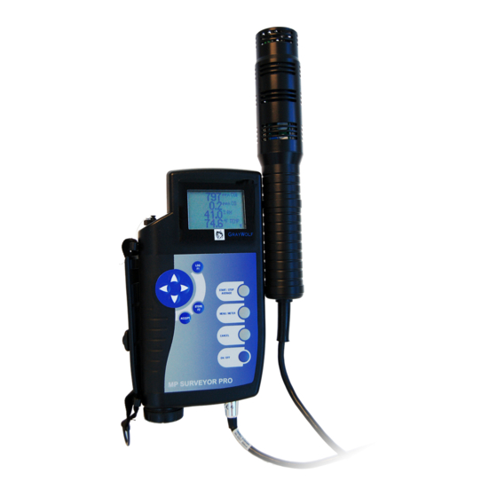
MAN IAQ Surveyor Issue 11 2004 1. INTRODUCTION INTRODUCTION The IAQ Surveyor Pro and IAQ Surveyor II (Figure 1) are two instruments capable of measuring a variety of air parameters. These parameters include airspeed, temperature, relative humidity, CO, CO , etc depending on the type of probe connected to the instrument. -
Page 18: Main Features
MAN IAQ Surveyor Issue 11 2004 1. INTRODUCTION MAIN FEATURES 1.2.1 IAQ Surveyor Pro a. Auto data logging with log download to PC. b. Two smart probe sockets. c. Supports all types of smart probe. d. Supplied with 1260GSS IAQ Multi-parameter probe as standard. -
Page 19: Power Supplies
Rechargeable batteries must be removed from the instrument and recharged externally using a proprietary battery charger. Alternatively the instrument may be operated from an external GrayWolf AC Adaptor operating from a 110/240 V ac supply. Note: When the adaptor is plugged into the instrument the internal batteries are automatically disconnected. -
Page 20: Battery Life
MAN IAQ Surveyor Issue 11 2004 1. INTRODUCTION used. BATTERY LIFE Approximately 30 hours: Using a1260GSS IAQ Multi- parameter probe Approximately 170 hours: Using a 2300AHTS Multi- parameter probe (assumes zero air speed) PROBE CONNECTIONS Both versions of the instrument may operate two smart probes simultaneously. -
Page 21: Connecting Auxiliary Equipment
The following equipment may be connected to the accessories socket: An ac adaptor. Equipment such as a PC or printer. The GrayWolf ACC-ADY125-CL Y adaptor may be used when connecting both the ac adaptor supply and the external equipment to the instrument. -
Page 22: Keypad Functions
The thermocouple channel will display 3 arrows until a thermocouple probe is connected (not Surveyor II). If the IAQ Surveyor Pro does not detect a probe connection, e.g. if the connector has not been fully inserted, the display will only show the built in thermocouple and micromanometer readings. - Page 23 MAN IAQ Surveyor Issue 11 2004 1. INTRODUCTION simultaneously. However, where information extends beyond that displayed, scrolling arrows are shown on the right hand side of the display as shown below: Use the cursor keys to scroll the display up or down to show ppm CO ppm CO 74.2...
-
Page 24: Modes Of Operation
Issue 11 2004 1. INTRODUCTION The instrument is in the duct averaging mode. (IAQ Surveyor Pro only) The instrument is carrying out a preprogrammed logging function (referred to as Continuous logging). A fully programmed logging sequence is set up and waiting (referred to as Autostart). -
Page 25: Meter Mode
MAN IAQ Surveyor Issue 11 2004 1. INTRODUCTION The instrument displays the probe instantaneous readings and the sequence of keypad operations is as shown below: 1.8.3 Menu Mode To switch on press the ON/OFF key A start-up screen is shown briefl y Switch off (from any screen) Continuous logging... -
Page 26: Menu Mode
MAN IAQ Surveyor Issue 11 2004 1. INTRODUCTION The Menu mode allows operations to be carried out such as probe sensor calibration, set up and confi guration of site and location references, alarm level settings, date and time, etc. Any of these confi guration procedures can be aborted by pressing the CANCEL button. -
Page 27: Using The Instruments
MAN IAQ Surveyor Issue 11 2004 2. USING THE INSTRUMENTS 2.1 GETTING STARTED The instrument automatically detects the type of probe connected to it and displays the appropriate measurement units. The instrument screen displays shown in this section assume that a 1260GSS IAQ Multi-parameter probe (four function probe) is connected to the instrument. -
Page 28: Using The Instrument Information Facility
MAN IAQ Surveyor Issue 11 2004 2. USING THE INSTRUMENTS To switch off, press and hold the ON/OFF button until the display 3, 2, 1 countdown is complete. USING THE INSTRUMENT INFORMATION FACILITY 2.2.1 General The default settings of the instrument may be displayed on the Instrument Info screen. -
Page 29: Details On The Instrument Info Screen
MAN IAQ Surveyor Issue 11 2004 2. USING THE INSTRUMENTS Press the MENU/METER button to return to the Measurement screen. 2.2.3 Details on the Instrument Info Screen Parameter details, as shown on the Instrument Info screen, are read only. Scroll to show details that are not immediately visible by pressing the up/down ( ) cursor keys. - Page 30 MAN IAQ Surveyor Issue 11 2004 2. USING THE INSTRUMENTS the log memory is full. This reading is calculated on the probes currently connected and the channels that are enabled. Log Used Approximate percentage of the log memory capacity that contains data. Key Beep ON/OFF refers to the beep that sounds each time one of the instrument buttons is pressed.
-
Page 31: Using The Instrument Setup Facility
MAN IAQ Surveyor Issue 11 2004 2. USING THE INSTRUMENTS Prb 2 Filter Whether the probe has adaptive fi ltering enabled. Prb 3 S/No Serial number of the internal probe. (not implemented in IAQ Surveyor II) Prb 3 Ver. Version number of the internal probe confi... -
Page 32: Getting To The Instrument Setup Screen
MAN IAQ Surveyor Issue 11 2004 2. USING THE INSTRUMENTS Once changed, the new default settings are retained when Press MENU/METER Press the down arrow to highlight Instrument Setup ppm CO ppm CO MAIN MENU 74.2 View Min/Max/Avg Channel Setup.. Press ACCEPT 23.8 Data Logging.. - Page 33 MAN IAQ Surveyor Issue 11 2004 2. USING THE INSTRUMENTS Provides an optional sounding of the bleeper with each key press, or when an alarm condition has been exceeded. With Bleeper Setup highlighted, press ACCEPT to display the Bleeper Setup screen. Use the cursor up/down arrows to highlight Keypress or Alarm as required.
- Page 34 MAN IAQ Surveyor Issue 11 2004 2. USING THE INSTRUMENTS 2.3.3.3 Printer Sets the instrument to suit the printer that is connected to the instrument. With Printer highlighted, press ACCEPT to display the Printer Setup screen. Use the cursor up/down arrows to highlight Cols or Line Feed as required.
- Page 35 To unlock, press the left and right cursor arrows at the same time. If one arrow is pressed slightly ahead of the other, the prompt: Keypad is Locked is displayed. 2.3.3.5 Autozero (IAQ Surveyor Pro only) Provides adjustment of the time period at which the micromanometer autozero function operates.
-
Page 36: Using The Channel Setup Facility
MAN IAQ Surveyor Issue 11 2004 2. USING THE INSTRUMENTS the value press the up cursor arrow, to decrease the value press the down arrow. Press ACCEPT to return to the Instrument Setup screen. USING THE CHANNEL SETUP FACILITY 2.4.1 General The units and alarm levels for each probe sensor can be displayed using the Channel Setup facility. -
Page 37: Using The Channel Setup Options
MAN IAQ Surveyor Issue 11 2004 2. USING THE INSTRUMENTS 2.4.2 Getting to a Channel Setup Screen. With the Measurement screen displayed, press the MENU/METER button to show the Main Menu screen. On the Main Menu screen, use the down arrow key to highlight the Channel Setup option. - Page 38 MAN IAQ Surveyor Issue 11 2004 2. USING THE INSTRUMENTS Highlight the required units and press ACCEPT (display returns to the Setup screen). 2.4.3.2 Calibrate Sensor Refer to Section 6 for details. Set TEMP Alarms Lower Limit +0065.0 Upper Limit +0082.0 Low Alarm 2.4.3.3 Set Alarms...
-
Page 39: Changing The Alarm Limits
MAN IAQ Surveyor Issue 11 2004 2. USING THE INSTRUMENTS disable the channel. The menu option will then change to Enable Channel. The channel is now disabled. With Enable Channel highlighted, press ACCEPT to enable the channel. The menu option will change to Disable Channel The channel is now enabled. -
Page 40: Displayed Channel Information
MAN IAQ Surveyor Issue 11 2004 2. USING THE INSTRUMENTS To change the lower and upper alarm limits: On the appropriate Set Alarms screen, highlight either Lower Limit or Upper Limit as required. Press the cursor right arrow, to highlight the least signifi... -
Page 41: Using The Min/Max/Average Facility
MAN IAQ Surveyor Issue 11 2004 2. USING THE INSTRUMENTS On the selected setup screen, highlight Channel Info... and press accept. The channel information displayed from a channel setup option comprises: 2.4.5.1 Last Cal. Refers to the date on which the channel was last calibrated. -
Page 42: Viewing The Mm/Max/Average Values
MAN IAQ Surveyor Issue 11 2004 2. USING THE INSTRUMENTS for datalogging. For the min/max/average values to be meaningful, they must be reset manually (see Section 2.5.3). The resultant calculated values can be viewed by selecting the View Min/Max/Avg option of the Main Menu. These values are updated approximately once every second while being displayed. -
Page 43: Resetting The Mm/Max/Average Values
MAN IAQ Surveyor Issue 11 2004 2. USING THE INSTRUMENTS arrows (eg Move between the four screens by using the cursor left/ right arrows. Press METER/MENU to return to the Measurement screen. 2.5.3 Resetting the Min/Max/Average Values Min/max/average calculations are cleared by using the Clear Min/Max/Avg option of the Main Menu, by changing a probe or by switching off the instrument. - Page 44 MAN IAQ Surveyor Issue 11 2004...
-
Page 45: Micromanometer And Thermocouple
Issue 11 2004 3. MICROMANOMETER AND THERMOCOUPLE GENERAL The IAQ Surveyor PRO, but not the IAQ Surveyor II, has a built-in Micromanometer and type k Thermocouple socket. The Micromanometer can be used to measure differential pressure or, in conjunction with a pitot static tube, to provide a direct indication of velocity and volume fl... -
Page 46: Pressure Measurements
MAN IAQ Surveyor Issue 11 2004 3. MICROMANOMETER AND THERMOCOUPLE Depending upon the application, the pressure differential can be used to indicate pressure, a velocity or calculate volume fl ow rate (VFR) if the duct area is programmed into the instrument. Used in conjunction with a pitot static tube, the micromanometer is particularly useful in determining the parameters of air fl... -
Page 47: Autozero Facility
MAN IAQ Surveyor Issue 11 2004 3. MICROMANOMETER AND THERMOCOUPLE 3.3.3 Auto Zero Facility The auto zero facility is particularly useful in applications where ambient temperature changes occur during the measurement procedure. At user selectable intervals, the instrument automatically resets the instrument zero by disconnecting the external pressure circuit and connecting together the two input pressure ports for approximately fi... -
Page 48: Volume Flow Rate
MAN IAQ Surveyor Issue 11 2004 3. MICROMANOMETER AND THERMOCOUPLE Notes: 1. Normally, the light colored, or clear, silicone tubing is used for the positive pressure connection (+VE) and the dark colored silicone tubing for the negative pressure connection (-VE). 2. - Page 49 MAN IAQ Surveyor Issue 11 2004 3. MICROMANOMETER AND THERMOCOUPLE Table 1 Instrument Display Ranges Units Range (±) Zero Displayed Indication Resolution Pressure Indications ±7000 Pa 0.1 Pa mm H 700.00 0.00 0.01 mm H in H ±30.000 0.000 0.001 in H mbar ±70.00 0.00...
-
Page 50: Duct Averaging - Storing Readings
Issue 11 2004 3. MICROMANOMETER AND THERMOCOUPLE 3.3.6 Duct Averaging - Storing Readings The IAQ Surveyor Pro provides a facility to record measurements as a duct is traversed and then to automatically calculate the average values. To enter the duct averaging mode: 100.0... - Page 51 MAN IAQ Surveyor Issue 11 2004 3. MICROMANOMETER AND THERMOCOUPLE Select View Results and press ACCEPT. Select site and location and press ACCEPT. Select Session and press ACCEPT. Select appropriate channel (such as velocity) and press ACCEPT. The instrument will display the minimum, average and maximum readings obtained during the traversing period.
- Page 52 MAN IAQ Surveyor Issue 11 2004...
-
Page 53: Datalogging Facilities
MAN IAQ Surveyor Issue 11 2004 4. DATALOGGING FACILITIES GENERAL Once the instrument has been set up with an appropriate probe, each channel that is required to record is switched on, checked and set to the required units, individual measurements may be Stored or a longer term Log may be initiated. -
Page 54: Adding A New Site Or Location Reference
MAN IAQ Surveyor Issue 11 2004 4. DATALOGGING FACILITIES Navigate to the required Site or Location as detailed in Section 4.2.6. Press F1 to display the alphanumeric selection screen. Change the name of the Site or Location as described in Section 4.2.7. Note: When the name of a Location is changed, any existing logged data remains available under the new name. -
Page 55: Changing The Default Site/Location Reference
MAN IAQ Surveyor Issue 11 2004 4. DATALOGGING FACILITIES 4.2.4 Changing the Default Site/Location Reference If LOG or STORE is pressed with the Measurement screen displayed, confi rmation is required that the default Site/ Location is the reference against which the data is to be stored. -
Page 56: Navigating To A Site And Location
MAN IAQ Surveyor Issue 11 2004 4. DATALOGGING FACILITIES Navigate to the required Site/Location as described in Section 4.2.6 and press ACCEPT to display the Delete What? screen. Select Data Only or Data & Site and press ACCEPT. Confi rm the deletion. Press ACCEPT to returned to the Delete Site/Loc screen. -
Page 57: Using The Alphanumeric Selection Screen
MAN IAQ Surveyor Issue 11 2004 4. DATALOGGING FACILITIES Use the cursor up/down arrows to select the required Location. If necessary, press the cursor left arrow to return to the list of Sites. 4.2.7 Using the Alphanumeric Selection Screen Use the alphanumeric selection screen to add, or rename, a Site or Location (see Sections 4.2.2 or 4.2.3). -
Page 58: Logging The Environmental Conditions
MAN IAQ Surveyor Issue 11 2004 4. DATALOGGING FACILITIES Note: If ACCEPT is pressed instead of F1, the name is accepted as it is and if this is incorrect the rename process will have to be repeated (see Section 4.2.2). As necessary, use the following options to complete the renaming of the Site or Location. -
Page 59: Storing Individual Probe Measurements
MAN IAQ Surveyor Issue 11 2004 4. DATALOGGING FACILITIES Removal of a probe. Pressing the STORE F2 button. Stopping and starting another continuous log session. Sessions are displayed based upon the start time. 4.3.2 Storing Individual Probe Measurements To store individual probe measurements (eg. for a spot check IAQ survey): Press the STORE button. -
Page 60: Using The Data Logging Autostart Facility
MAN IAQ Surveyor Issue 11 2004 4. DATALOGGING FACILITIES restricted number of options. the logging interval, the measurement units or the alarm levels cannot be changed. During a continuous logging session, a sensor cannot be calibrated or disabled, or a Site or Location ppm CO deleted. - Page 61 MAN IAQ Surveyor Issue 11 2004 4. DATALOGGING FACILITIES The instrument can be set to log overnight, for example, at start and fi nish times when it is known that a building will be unoccupied. Autostart allows the instrument to automatically start and stop a continuous logging session using start and stop times specifi...
- Page 62 MAN IAQ Surveyor Issue 11 2004 4. DATALOGGING FACILITIES screen. Highlight Data Logging and press ACCEPT to display the Data Logging screen. Highlight Log Timing and press ACCEPT to display the Log Timing screen, with Interval highlighted. The time shown is the default time interval. If necessary, change the default time interval by pressing the cursor right arrow once to highlight the units of minutes, or twice to highlight the units of...
- Page 63 MAN IAQ Surveyor Issue 11 2004 4. DATALOGGING FACILITIES Similarly, set the Finish time. About the Start and Finish times of Autostart: The displayed Start and Finish times both default to the current time and date. To use Autostart, the Finish time must be changed.
-
Page 64: Setting The Default Logging Interval
MAN IAQ Surveyor Issue 11 2004 4. DATALOGGING FACILITIES ACCEPT and the LOG symbol is displayed. Note: Logging starts at the Start time, it does not wait for the ACCEPT to be pressed. 4.3.5 Setting the Default Logging Interval Press MENU/METER to display the Main Menu screen. -
Page 65: General
MAN IAQ Surveyor Issue 11 2004 4. DATALOGGING FACILITIES 4.4.1 General Data that has been logged to the instrument can be viewed on the instrument display, selectively deleted or printed to a printer that is attached to the instrument. Alternatively, these procedures can be carried out more effectively by using the WolfSensePC Software. -
Page 66: Deleting Logged Data
MAN IAQ Surveyor Issue 11 2004 4. DATALOGGING FACILITIES An attempt to change the time/date past that for which there is data is ignored. Press ACCEPT to display the logged data, starting at the time specifi ed in step (5). After viewing the data, press MENU/METER to return to the Measurement screen. - Page 67 MAN IAQ Surveyor Issue 11 2004 4. DATALOGGING FACILITIES Logged data can be deleted either by initialising the complete log memory or by deleting data at individual Site/Location references. CAUTION Before deleting any log data, ensure that there is no further use for it by viewing the data (see Section 4.4.2) or printing it out (see Section 4.4.4).
-
Page 68: Printing Logged Data
MAN IAQ Surveyor Issue 11 2004 4. DATALOGGING FACILITIES also removed. Press ACCEPT to confi rm the deletion and the prompt Now deleting, please wait is displayed. The display returns to the Delete Site/Loc screen. Delete data at any other Sites or Locations as required. - Page 69 Note: Alternatively, the WolfSensePC Software may be used to print stored data to a printer that is attached to your Connect the GrayWolf printer cable (reference ACC- CA1-PR) to the instrument external accessories connector (7-pin DIN).
- Page 70 MAN IAQ Surveyor Issue 11 2004 4. DATALOGGING FACILITIES the Data Logging screen. Highlight Print Logged Data and press ACCEPT to display the Print Logged Data screen, which allows selection of the required Site/Location. Navigate to the required Site/Location as described in Section 4.2.6.
-
Page 71: Pc Software
MAN IAQ Surveyor Issue 11 2004 5. PC SOFTWARE GENERAL The IAQ Surveyor Pro and IAQ Surveyor II can be connected to a PC in order to download logged data to a Microsoft Excel spreadsheet. A software utility (WolfSensePC) is available to enable transfer of the data to a hard disk and provide basic graphical analysis. - Page 72 MAN IAQ Surveyor Issue 11 2004...
-
Page 73: Calibration Procedures
(see Section 4.2). If a probe or sensor fails to calibrate, it should be returned to GrayWolf or one of their approved agents for repair or replacement. USING THE QUICK CAL FACILITY This procedure is not applicable for all sensors (i.e. -
Page 74: Changing The Calibration Levels
MAN IAQ Surveyor Issue 11 2004 6. CALIBRATION PROCEDURES display the Calibration screen for the selected sensor. With Quick Cal (Zero Only) highlighted, press ACCEPT. The prompt Zeroing Sensor, Are you sure? will be displayed. Press ACCEPT to zero the sensor at the default low calibration level (refer to Section 6.3.2 to change this calibration level). -
Page 75: Setting New Calibration Levels
MAN IAQ Surveyor Issue 11 2004 6. CALIBRATION PROCEDURES 6.3.2 Setting new Calibration Levels Display the channel Setup screen for the appropriate sensor as described in Section 2.4.2. With Calibrate Sensor highlighted, press ACCEPT to display the Calibration screen for the selected sensor. With Do Standard Cal Setup highlighted, press ACCEPT to display the associated Cal Setup screen. -
Page 76: Reverting To The Factory Settings
MAN IAQ Surveyor Issue 11 2004 6. CALIBRATION PROCEDURES (10) Repeat Steps 5 to 7 to adjust the Calibration Time. Note: Cal Time digits are adjusted by positioning the cursor to the left of the required digit. (11) Press ACCEPT to return to the Calibration screen and MENU/METER to return to the Measurement screen. -
Page 77: Maintenance Procedures
MAN IAQ Surveyor Issue 11 2004 7. MAINTENANCE PROCEDURES INTRODUCTION Routine maintenance of the instruments consists of external care only. Except for the batteries, there are no user serviceable parts inside the instrument. Opening the instrument voids the warranty. This section provides details of the recommended preventive maintenance, advice on battery maintenance and lists some simple checks that can be carried out if operational problems are experienced. -
Page 78: Rechargeable Batteries
Basic problems that may encountered with the instruments are listed in Table 3 and a summary of possible displayed warnings in Table 4. SERVICE GrayWolf offers calibration and repair services at many locations throughout the world. Contact GrayWolf for details of your nearest Service Location. - Page 79 The time required for servicing the Surveyor instruments depends on whether the instrument is returned to a GrayWolf Service Location or if it can be repaired or replaced locally. For instrument returns in the UK or North America,...
- Page 80 MAN IAQ Surveyor Issue 11 2004 7. MAINTENANCE PROCEDURES Table 2 Basic Problems and Suggested Remedies Suggested Remedies Problem Checks Press the On/Off button. Display is blank. Is the instrument switched on? Check that the battery end cap Are the batteries inserted and is screwed in fully.
- Page 81 MAN IAQ Surveyor Issue 11 2004 7. MAINTENANCE PROCEDURES Table 2 Basic Problems and Suggested Remedies (Cont.) Problem Checks Suggested Remedies sensors of a Multi Is the sensor disabled? Check your original order. Function probe. Try another probe. Was the probe ordered with a full set of sensors? Calibrate using known good Is the probe damaged or...
- Page 82 MAN IAQ Surveyor Issue 11 2004 7. MAINTENANCE PROCEDURES Table 3 Summary of the Warning Messages Warning Warning Text Reason for Warning Refer To Ref. Section 1001 Sensor Failed to Zero Displayed when a sensor cannot be zeroed (Quick Cal), either because of a faulty sensor or the sensor output is not within the zeroing range.
- Page 83 MAN IAQ Surveyor Issue 11 2004 7. MAINTENANCE PROCEDURES Table 3 Summary of the Warning Messages (Cont.) Warning Warning Text Reason for Warning Refer To Ref. Section No data is logged at this Displayed if you try to print log 4.4.1 1011 location.
- Page 84 MAN IAQ Surveyor Issue 11 2004 7. MAINTENANCE PROCEDURES Table 3 Summary of the Warning Messages (Cont.) Warning Warning Text Reason for Warning Ref. Displayed when manually trying to log a 1019 Autostart enabled or running. reading whilst logging is running. Probe is not supported by the instrument.
-
Page 85: Specification
130 mm (5.12 inches). Length: 260 mm (10.24 inches). Weight (Including Battery): IAQ Surveyor II 815 g (28.8 oz) IAQ Surveyor Pro 893 g (31.5 oz) DISPLAY Liquid Crystal Display (LCD): 128 x 64 point dot matrix. Viewing Area: 65 mm (2.55 inches) x 40 mm (1.6 inches). -
Page 86: Environmental
MAN IAQ Surveyor Issue 11 2004 8. SPECIFICATION ENVIRONMENTAL Operation Range: -10°C (+15°F) to +55°C (+131°F). 0 to 100% rh (non condensing) Storage Range: -20°C (-5°F) to +60°C (+140°F) 0 to 100% rh (non condensing) ELECTROMAGNETIC COMPATIBILITY (EMC) Within the limits of EMC Directive 89/336/EEC, the design of the instrument has been tested to EN 50270:1999 and is compliant with respect to RFI, ESD and RF emissions. -
Page 87: Measurement Ranges
MAN IAQ Surveyor Issue 11 2004 8. SPECIFICATION MEASUREMENT RANGES Quantity to Avaialable Measurement be Measured Probe Range Relative 1260GSS Multi- 0 to 100% rh. Humidity Function Probe Relative 2300AHTS Multi- 0 to 100% rh. Humidity Function Probe Dewpoint 1260GSS Multi- -45°C to +71°C. - Page 88 Volumetric 2300AHTS Multi- 0 to 1198 M /min. Flow Rate function Probe 0 to 19.98 M /sec. 0 to 42,300 ft /min. 0 to 2,540,113 ft /hr. IAQ Surveyor Pro only. When used with a pitot static tube (not included).
-
Page 89: Probes And Accessories
Differential Pressure probe, with auto zeroing. (Discontinued) 561LPS Hotwire Anemometer (Discontinued) Vane Anemometer (Discontinued) 129MSS Pitot Static Tube 228MSS Optical Tachometer (Discontinued) 229MS Particle Counter (Discontinued) 327TMS 1401PCS HVAC Multi-function Probe 2300AHTS GRAYWOLF ACCESSORIES AVAILABLE FOR USE WITH THE SURVEYOR INSTRUMENTS... - Page 90 MAN IAQ Surveyor Issue 11 2004 9. PROBES AND ACCESSORIES Carrying Case (included) PCC-31-CL AC Adaptor ACC-AA2-CL PC Cable (included) ACC-CA1-CL Printer Cable ACC-CAP-CL Printer ACC-PR1 Power/Comms Y Adaptor Cable ACC-ADY125-CL Gas Calibration Kit (CO/CO CA-GCK4-CL Relative Humidity Calibration Kit CA-HC4-COL 1.5m dual tubing (included with ACC-bbTU6...
-
Page 91: Pitot Static Tubes And Accessories
Flexible tubes, which are pre-fi tted to the total (clear tube) and static (dark tube) outputs, and are suitable for connection to the IAQ Surveyor Pro pressure ports. Marker pen, which can be used as an alternative to the spring clip depth markers. -
Page 92: Specifications
MAN IAQ Surveyor Issue 11 2004 10. PITOT STATIC TUBES AND ACCESSORIES 10.2 SPECIFICATIONS Note: Unless stated otherwise, the following details apply to all the pitot static tubes. 10.2.1 Nose and Head Section Type: NPL MENC, all welded construction. Design Standard: BS 1042 Pt 2A 1973. - Page 93 MAN IAQ Surveyor Issue 11 2004 10. PITOT STATIC TUBES AND ACCESSORIES...
- Page 94 MAN IAQ Surveyor Issue 11 2004...
- Page 95 MAN IAQ Surveyor Issue 11 2004 APPENDIX A GLOSSARY OF TERMS AND ABBREVIATIONS The following terms and abbreviations are used in this Manual or are associated with surveys of Indoor Air Quality: Air handling unit. Alarm condition Condition that exists when an alarm level has been exceeded, but which is ignored unless the channel has been enabled.
- Page 96 MAN IAQ Surveyor Issue 11 2004 APPENDIX A GLOSSARY OF TERMS AND ABBREVIATIONS at the logging time interval. Started and fi nished, by pressing the LOG button. Countdown Delayed switch off to avoid accidental use of the ON/OFF button. Cursor key 4-way switch on the Surveyor instruments front panel.
- Page 97 MAN IAQ Surveyor Issue 11 2004 APPENDIX A GLOSSARY OF TERMS AND ABBREVIATIONS Line feed Printer function, to move to the next line. Most printers have line feed as an automatic function. Location Reference for logged measurements. Sub division of a Site. og data Stored information for each channel that was enabled during a logging session.
- Page 98 Underrange Measurement is less than the selected range. Volume fl ow rate. WolfSensePC Software GrayWolf software system that enables the Surveyor instruments to be confi gured from a PC, and also to display logged data in various formats. Y adaptor...
- Page 99 MAN IAQ Surveyor Issue 11 2004 APPENDIX B USEFUL CONVERSIONS PRESSURE CONVERSIONS Useful Approximations 1 Pascal 0.010 mbar 7.501 x 10 mm Hg 0.01 mbar 0.102 mm H O 1.451 x 10 0.1 mm H 0.004 inch H O 9.869 x 10 10 x 10 1 mbar 100.0 Pa...
- Page 100 Issue: 11 2004 GrayWolf Sensing Solutions, LLC 12 Cambridge Dr. Trumbull, CT 06611 Phone: 203-416-0005 Fax: 203-416-0002 GrayWolf Sensing Solutions, LTD Tuamgraney Industrial Estate Tuamgraney, Co Clare, Ireland Phone: (353)61921736 Fax: (353)61921528 Distributor: This publication is not intended to form the basis of a contract, and the company reserves the right to amend the design and specifi...
Need help?
Do you have a question about the IAQ SURVEYOR PRO and is the answer not in the manual?
Questions and answers