
Subscribe to Our Youtube Channel
Related Manuals for Innogy eClick


Summary of Contents for Innogy eClick
- Page 1 Technology eClick installation instructions for eBox smart, professional and touch (Generation 3.5)
- Page 2 instructions...
-
Page 3: Table Of Contents
Content Content Safety information Connection options Scenario A: eClick electrical connection without eSmartMeter, simple supply Scenario B: eClick electrical connection Qualifications for electrical work with eSmartMeter, simple supply Electric vehicle charger Scenario C: eClick electrical connection characteristics according to IEC 61851-1 Ed. 3... -
Page 4: Safety Information
IMPORTANT Considerable risk of injury/damage to property IMPORTANT! There is a risk of injury or damage to property! The eClick must be installed by qualified, specialised electricians. NOTE Information on optimising the application Observing this information can improve the product’s application. -
Page 5: Qualifications For Electrical Work
Safety information Important Note Important Danger Important Make sure that all eBox bases have eBox professional is Handling live components incorrectly may The contents of components are dry a maintenance-free sharp edges. Do not cause grievous injuries and death. So the delivery must during installation. - Page 6 7. The product can be installed on walls and to compatible Pole (ePole or ePole duo) products. 8. The product eClick in conjunction with the eBox is rated electrical protection class I. The open eClick is rated electrical protection class I.
-
Page 7: General And Electrical Specifications
3.7/4.6/7.4/11/13.8/22 kW (16 A, 20 A, 32 A; one* or three-phase) Grid eClick: rotating current 400 V AC, three-phase, 32 A (22 kW)/20 A (13.8 kW)/16 A (11 kW) or input power alternating current 230 V AC, one-phase, 32 A (7.4 kW)/20 A (4.6 kW)/16 A (3.7 kW) Output power eClick: rotating current 400 V AC, three-phase, 32 A (22 kW)/20 A (13.8 kW)/16 A (11 kW) or... -
Page 8: Product Overview
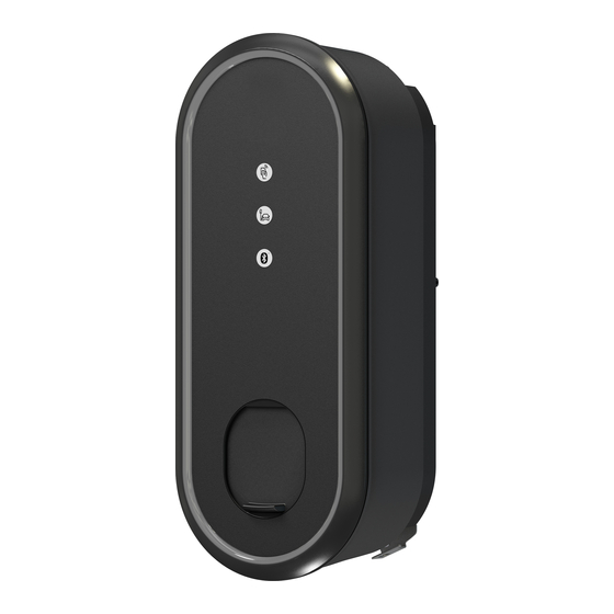
Product overview The eClick is the docking station for the eBox variants. Together, eClick and eBox form the charger for eMobility solutions. Thanks to its modular design, the eClick can also be installed without the eBox, which is then fitted at a later time. Please observe the safety instructions at the beginning of these installation instructions. -
Page 9: Eclick - The Product Details
Product overview eClick – the product details eClick Contact guard Cable routing plates Locking bracket Mains board eSmartMeter (optional) Sealing plug Interface board Specifications Measurements H x W x D Approx. 399 mm x 155 mm x 62 mm Installation type Wall;... -
Page 10: Choosing The Site
For wall installation, also ensure that the surface on which the eClick is to be installed is even. If the surface is uneven, When selecting the installation location, please ensure it may be difficult to install and moisture may penetrate. -
Page 11: Pre-Installation Requirements
Check and ensure that the electrical installation intended for connection can supply the required electrical power. Each eClick must be fused with its own RCD and its own circuit breaker in the pre-installation. No additional electrical devices may be integrated in any of these circuits. -
Page 12: Installation
If necessary, install the eSmartMeter installation. lock nut. in the eClick, and connect it to the mains board. 4. Pre-installation: Make sure that a 6b. FNN control box and shunt corresponding RCD (see table below) release (optional): 7b. - Page 13 Use the provided seal to secure the 12. Perform electrical test. connected to L2 or L3! Supply contact guard on the eClick in such a 13. Go through checklist, p.34. line L1 must always be connected manner that unauthorised removal...
-
Page 14: European Grids
TN-C mains. If the pre-installation presents a transfer point from a TN-C to a TN-C-S mains, the eClick may be connected to the latter ac- cording to TN-C-S description. In other words, the TN-C mains must be converted... - Page 15 Assuming there is an earth electrode of verified suitability: single-phase connection: L1, N, PE, three-phase connection: L1, L2, L3, N, PE. eClick An IT mains is not supported. The eClick must not be connected directly to an IT mains! Important Danger Note Special requirements must be...
-
Page 16: Tools Needed
Tools needed To install the eClick to a wall or to ePole (duo), you will screwdriver with torque display. You will also need a side need a spirit level, the drilling template provided in the cutter, a pair of round-nosed pliers, and, for cable assembly, packaging, a pencil or other marker, an 8 mm drill bit, a a cable knife and a wire stripper. -
Page 17: Notes On Installation
Remove the insulation plugs from the eClick, and screw provided with the ePole duo. After securing, replace the the eClick to the points provided for this purpose in the insulation plugs. Repeat these steps on the opposite side. ePole duo. Use the screws (3x M6x16) and washers (3x 6.4) -
Page 18: Eclick Wall Installation
After choosing a suitable site and making all of the Danger The eClick must be installed on a preparations, you can now install the eClick. flat surface so that the eClick does not deform. - Page 19 Installation Screw the eClick to the wall using the Insert the provided sealing plugs. Important It is imperative that you insert the screws provided. provided sealing plugs, otherwise water or other substances may penetrate and damage the product.
-
Page 20: Esmartmeter Integration (Optional)
Insert a cable with a maximum cross-section of 10 mm². Remove the contact guard from the eClick (cf. previous page). It will be placed back on the eClick at the end of the installation. When delivered, the contact guard is snapped to four points on the eClick. -
Page 21: Esmartmeter Cabling
Installation eSmartMeter cabling As the last step before installation, eSmartMeter cabling Important must be carried out. The eSmartMeter supply cables must be placed on the mains board. Mains board Interface board Consult the figure to wire the Use the provided data cable to eSmartMeter to the mains board, connect the eSmartMeter to the and tighten the screws with a torque... -
Page 22: Preparing The Electrical Connection
Preparing the electrical connection Make sure that the hole in the cable routing plate is facing the side where you want to insert the supply cable. If not, draw out and exchange the plates. Important When inserting the cable routing plates, it is essential to ensure that they are flush. - Page 23 Insert the M20 cable gland (for Ethernet, AUX supply etc.). M20 cable gland Replace the routing plate in the eClick, and press it on firmly to ensure tightness. Feed the network cable through the M20 cable gland over the cable ducts and secure the cable to 4 using the cable clip.
-
Page 24: Shunt Release Connection (Optional)
12 V/24 V variant Shunt release (optional) Interface board To eClick mains board/eSmartMeter Shunt release The signal for welded power contacts is connected to L1 L2 L3 N position 7 of the interface board (see fig. p. 17). A change-over contact (max. - Page 25 Installation Connection The FNN control box connector can connect the eClick to an external control box. The interface board features 2 Note connection options for connecting the FNN control box. Communication between the FNN control box and the eBox There are 2 potential-free contacts available. Please note...
-
Page 26: Electrical Connection
It is recommended to remove the routing plates, to insert the cable, and to pre-bend the cores according to your configuration. When doing so, consult the figures on the following pages. -
Page 27: Without Esmartmeter, Simple Supply
This will simplify rerouting and subsequent eSmartMeter installation. Important Introduce the supply cable into the eClick from the top (T) If single-phase connection is required, the or the bottom (B). Now place the wires on the contacts... -
Page 28: Scenario A: Eclick Electrical Connection
Scenario B: eClick electrical connection with eSmartMeter, simple supply 1. Detach the cable routing plate from the top (T) or the bottom (B). 2. Introduce the cable through the routing plate, and cut Important to length. If single-phase connection is required, the mains board or 3. - Page 29 M20 cable gland. terminals with a torque of 1.2-1.5 Nm. 2. Replace the routing plate in the eClick, and press it on firmly to ensure tightness. 3. Firmly screw on the cable gland to ensure tightness.
- Page 30 M20 cable gland. plate and cut them to length. Then replace the cable rout- 2. Replace the routing plate in the eClick, and press it on ing plate. The eSmartMeter supply cables must be placed firmly to ensure tightness.
-
Page 31: Reading The Meter
1. Switch off the voltage after completion of the test in accordance with national electrotechnical standards. 2. Put the contact guard back into place on the eClick. 3. Use the provided seal to secure the contact guard on the eClick in such a manner that unauthorised removal... -
Page 32: Clicking The Ebox Into The Eclick
Clicking the eBox into the eClick After the electrical installation, the eBox can be clicked into the eClick. Before installing the eBox, make sure the supply to the eClick is disconnected. 90° LAN 3 RJ45 If an eSmartMeter is installed,... - Page 33 Clicking the eBox into the eClick Important Make sure that the flat ribbon data cables are not trapped between the eClick and eBox when mounting the eBox. Please continue to hold the eBox in place with one hand. Check the final...
- Page 34 • Cable routing plates inserted flush • Contact guard attached • Contact guard secured with seal Important • Ribbon data cable between eClick and eBox not Please note down the number of phases you have connected jammed and the maximum current on the •...
-
Page 35: Commissioning The Ebox
Commissioning the eBox Commissioning the eBox After the preceding steps, you can switch in the voltage. Bear in mind that the eBox does not light up until you have approached it within one metre. You will be prompted to link to the eBox via Bluetooth. To make this work, you need either the eConfig app or WebConfig. - Page 36 II.) Configuration via WebConfig You can download the instructions for using WebConfig via the following link innogy-emobility.com/documents III.) Commissioning during installation for private use: 1. Adjust the installed charging capacity in the eConfig app 2. To set up the eBox for the user, you can find more...
-
Page 37: Configuring The Power Connection
Maintenance/repair The eClick is a maintenance-free product. It does not contain any reparable parts or components. Do not carry out any repair work. In case of a permanent error, replace the eBox on the eClick or the eClick if required. -
Page 38: Disassembly
Disassembly Disassembly of the eClick must be carried out by a qualified eClick. Then remove the contact guard from the eClick electrician. and disconnect the power cable and, if necessary, the Ethernet cable of the local network. Unscrew the cable... -
Page 39: Imprint
This document is intellectual property right- and copyright-protected. No part hereof may be edited, duplicated, or published in any manner purposing other than the proper use of the eBox without express written permission of innogy eMobility Solutions GmbH. © innogy eMobility Solutions GmbH... - Page 40 Solutions GmbH UK sales partner Flamingoweg 1 innogy eMobility Limited 44139 Dortmund Windmill Hill Business Park Germany Swindon • SN5 6PB Great Britain emobility@innogy.com Printed on certified innogy-emobility.com 100% recycled paper.
Need help?
Do you have a question about the eClick and is the answer not in the manual?
Questions and answers