Advertisement
Quick Links
Advertisement

Related Manuals for FiSHAW UB200


Summary of Contents for FiSHAW UB200
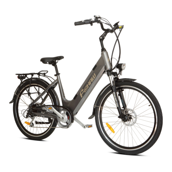
- Page 1 UB200 ASSEMBLY INSTRUCTIONS...
- Page 2 With a box cutter, cut the tape around the box with out damaging the box. Store the box in case you need to return your FiSHAW bike to us. Store the box somewhere dry and out of the way eg. Under your...
- Page 3 Remove the bike out of the box using a friend to lift it. Place the bike somewhere, where there is plenty of space to assemble the bike. Remove all other contents/ accessories from the box...
- Page 4 Remove zip ties with a pair of wire cutters and all packaging. Take care when cutting zip ties not to cut brake/electrical cables on the bike Box with accessories and front bicycle skewer with quick release which is zip tied to the front wheel.
- Page 5 Contents of accessories box as shown. Provided tool kit to assemble the bike...
- Page 6 Front wheel skewer with quick release Rotate the forks 180 degrees as shown by the arrow so that it faces the opposite position it was in. The correct direction of rotation is the one where all brake cables are free and not wrapped around the forks.
- Page 7 Insert the handle bar stem into the head tube of the bike frame. Using the correct sized allen key tighten the handle bar stem to the desired height and make sure the handle bars are square with the bike frame...
- Page 8 Turn the bike upside down to attach the front wheel. Remove the plastic forks bar protector...
- Page 9 Remove the plastic brake pad wedge from the caliper, this is used to keep a space open between the brake pads to make it easier for the brake disc to insert between the brake pads when installing the the front wheel to the forks. Place the front wheel between the forks making sure the disc brake is inserted between the brake pads of the caliper.
- Page 10 Quick release V shaped spring Skewer (axle) V shaped spring Skewer nut With the V shaped spring(4) and the skewer nut(5) remove. Insert the skewer with the V shaped spring(2) with the small end of the spring pointing towards the wheel. Push the skewer all the way through to the other side.
- Page 11 On the other side from where the skewer was inserted, add the other V shaped spring (4 with the smaller end of the spring facing the wheel Now screw on the skewer nut (5 tighten until it is touching the fork. On the quick release (1) side.
- Page 12 Take the front wheel mudguard, thread through the front of the forks starting from (2) till the top clip of the mudguard (1) is in behind the fork arch. Remove the allen key head bolt, washer and nut from the front forks with supplied allen key.
- Page 13 Remove the allen head screw and washer (2) from the front fork with the supplied allen key. Place the mudguard stem eye-lite (1) in position where the allen head screw was removed. Return the allen key head screw and washer (2) through the eye-lite of the mudguard stem(1) and tighten with supplied allen key.
- Page 14 Take the head light wire and insert the red wire into the head light contact (1) and the black wire insert into the head light contact(2). Make sure both wires are pushed on to contact well.
- Page 15 Thread the allen head bolt through the washer, head light stem(1) then through the arch of the front forks and the mudguard clip(2) then attach the nut to the allen head bolt and tighten with the allen key and using the spanner on the nut Before fully tightening the allen bolt and nut, make sure the head light is plum with the bike frame.
- Page 16 Insert the correct peddle marked left or right into the crank arm and screw into the crank arm using your fingers at first. Caution should be taken not to cross thread while screwing the peddle into place Once you have threaded the peddle on with your fingers, tighten with the correct size spanner supplied in your tool kit.
- Page 17 Undo the allen head screw with the correct allen key supplied. Pull the bike rack arm (1) out and line up with the screw hole and screw the allen head screw back in place...
- Page 18 Push the bike rack forward or back until you find it sitting level. Once level, tighten off the nut on the bike rack Before riding, it is important to completely check over the bike that everything is fitted correctly, that all cables are free by turning the handle bars left and right.
Need help?
Do you have a question about the UB200 and is the answer not in the manual?
Questions and answers