Table of Contents
Advertisement
Quick Links
Advertisement
Table of Contents

Related Manuals for Emery Winslow 7600E

Summary of Contents for Emery Winslow 7600E
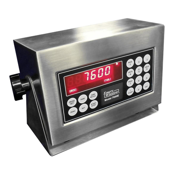
- Page 1 Model 7600E Configuration and Setup V3.41...
- Page 2 Emery Winslow Scale Company 73 Cogwheel Lane 4530 North 25th Street Seymour, CT 06483 Terre Haute, IN 47805 (203) 881-9333 (812) 466-5265 (203) 881-9477 FAX (812) 466-1046 FAX Alternate Packaging for extreme wash-down and with Totalizer in common enclosure...
-
Page 3: Table Of Contents
TABLE OF CONTENTS SPECIFICATIONS……………………………………...3 INSTALLATION…………………………………………4 SETUP ACCESS…………………………………….….5 MENU LAYOUT...………………………………………6 CONFIGURATION….…………………………………..7 REMOTE SERIAL DISPLAY………………………….8 CALIBRATION………………………………………….9 SERIAL PORTS………………………………………10 SERIAL COMMUNICATIONS……………………….11 ANALOG OUTPUT……………………………………13 DIGITAL INPUT/OUTPUT……………………………15 SETPOINTS……………………………………………16 OVER/UNDER…………………………………………17 BATCH MODE…………………………………………18 SERIAL COM. SETPOINT/ACC……………………..19 TIME & DATE…………………………………………..20 WEIGH IN/OUT………………………………………..21 SMART SERIAL……………………………………….23 ASCII CHART………………………………………….28 DISPLAY MESSAGES………………………………..32 ADDITIONAL SERIAL COMMANDS……………...…33 115/220 VAC…………………………………………..34 SPARE PARTS………………………………………..35... -
Page 4: Specifications
SPECIFICATIONS LOAD CELL A/D CONVERTER TYPE: 24 bit delta sigma EXCITATION: 5 VDC, 120 mA max. SIGNAL INPUT: 16 mv SENSITIVITY: 0.1 uV/grad UPDATE RATE: 30 update/second DISPLAY: Six (6) Decades, 0.6 inch LED KEYPAD: Full numeric plus controls POWER INPUT: 117/217 VAC, 50‑60 HZ, 20 watts, fuse 0.25 A Slo-Blow. SERIAL PORTS: Port 1: RS232C or 20ma Port 2: RS485, RS232C or 20mA. -
Page 5: Installation
INSTALLATION POWER WIRING: The indicator is designed to be operated from 117/217 VAC, 50‑60 Hz. The unit power cord must be plugged into a grounded 3 ‑ wire polarized AC wall socket. All normal wiring and grounding precautions should be observed, including use of a "clean"... -
Page 6: Setup Access
SETUP ACCESS:To access instrument configuration, calibration or to enable op- tions, depress the “Zero” key for five seconds. The Audit Trail counters (“Pxxxx” and “Cxxxx”) are displayed first followed by access code request (“AC?”). The initial factory setting is “0000” which is entered with four numeric “0”’s and enter (ENT). -
Page 7: Menu Layout
Menu Layout Configuration: Divisions, count by, decimal, over range, filter, AZM, zero range, ISM, lb/kg, serial port selection, DIO enable Calibration: Zero, Span Analog Output: Gross, Net, Display; Zero, Span, Trim Setpoint DIO: Setpoint, Over/Under, Manual / Auto Batch Time & Date: 24 hr, 12 hr, Print format Weigh –... - Page 8 CONFIGURATION: “SEL.CFG” Use Gross/Net to enter the menu and step to each category, Tare Recall to select parameters. ENT to return to menu selection. Capacity is the combination of “1”, “2” and “3”. Step Parameters Definition Number of divisions x100 ,100 = 10,000 5, 10, 15, 20…100, 120…1000 divisions Count by selection10,000 divisions, count...
-
Page 9: Remote Serial Display
Remote Serial Display (RSD) Option In RSD mode the instrument can be set to work with another unit as a “remote” either as the main or the slave unit. Communication is pre-set for channel two only on both units. (RS232, 9600, 8, none) When in remote mode, re-access to the following selections requires using the in- ternal “cal”... -
Page 10: Calibration
CALIBRATION: “SEL.CL1/CL2” Use Gross/Net to enter the menu indicated by a flashing “C” on the left and live weight is displayed. Scale zero (dead load) or ad- justing span (single or multi-point) are independent. Therefore either can be done and repeated as necessary before exciting calibration. If an error has been made, exit without “storing”... -
Page 11: Serial Ports
SERIAL PORTS Port 1: RS232 duplex (Rx,Tx), 20ma (Tx). Port 2: RS232 duplex (Rx,Tx), 20ma (Rx,Tx), RS485, or RS422. Note: Position jumper on J2 for Port 2 receive selection. TB-2 Tx1, RS232 Rx1, RS232 Tx2, RS232 Rx2, RS232 Tx1, -20ma Tx1,Tx2,+20ma Tx2, -20ma Rx2,+20ma... -
Page 12: Serial Communications
Serial Communications Remote Commands <Z><cr> Zero Scale “Gross” mode, no motion, inside zero range. <N><cr> Switch to Net “Gross” mode with Tare stored. <G><cr> Switch to Gross “Net” mode. <T><cr> Auto Tare Switch to Net, no motion, not at “Gross” zero. - Page 13 G/N: One (1) character field data identification for weighing mode in continuous (computer) mode. Gross Mode = “G” (ASCII 071), Net Mode = “N” (ASCII 078) status: One (1) character data identification used in the continuous (computer) out- put mode to identify the status of the indicator. Characters are listed below in order of priority.
-
Page 14: Analog Output
OPTION 1: Analog Output J1,2: set jumper 1-2 for 0-10 vdc set jumper 2-3 for 4-20 ma Output 1 Option 1 Analog Output: “SEL.OP1” Use Gross/Net to enter the menu and step to each category, Tare Recall to select parameters. ENT to return to menu selection. DISPLAY Parameters Definition... - Page 15 OPTIONS 2: DIO AC Inputs; D1, D2 are not installed, J1 = short (underside), J2 = open, R1 – R4 = 18k (3w, 5%, flame proof). DC Inputs; D1, D2 are installed, J1 = open (cut trace), J2 = short, R1 – R4 = 1.5k (1/2w, 5%, carbon film).
- Page 16 Option 2 DIO: “SEL.OP2” First select the operating mode for “Setpoint”, “Over/Under”, “Manual or Auto Batch”. After setup, the parameters for the selection are entered from the weighing mode. Use Gross/Net to enter the menu and step to each category, Tare Recall to select parameters.
-
Page 17: Setpoints
Step Parameter Definition OFF, SP, OU.UN, bAt1, Mode select: setpoint, over/under (check bAt2 weighing), Manual Batch, Auto Batch Setpoint Off, s1, s1.p, s1.d, s.p.d, Setpoint. 1 + pre-act, + drib, + both, Set1- Dual A&B. Setpoint 1 tracks Gross, Net, Display, Gr, nt, dSP, Count Count Output on below reading (POS), inverted... - Page 18 Pressing any key other than “start” Prn, tAr, dln will pause and a second push will abort. 7600E uses Start/Stop panel switch Off, s1, s1.p, s1.d, s.p.d Setpoint. 1 + pre-act, + dribble, + both Setpoint 1 tracks Gross, Net, Display,...
- Page 19 Additional Serial Commands: Setpoint/Accumulator Totalizer/Accumulator reset command. Send TC<CR> to reset the totalizer, and the meter responds with a TC+<CR><LF> string. Ten/Nine-digit Accumulator Printing/Serial Format Output Description COMMAND Output 10/9-digit w/ printable units (e.g., lb or kg) TR1<CR> “ 57.85 lb” 10/9-digit w/ computer units (e.g., L or K) &...
-
Page 20: Batch Mode
Time & Date ---, 24H, 12A, 12P Skip time, 24 hour, 12 hour am, 12 hour pm Set time: hh mm ss Set date: mm dd yy Month print selection, short numerical (mm/ S.no, no, Let dd/yy), number 01 thru 12, month spelled Off, Un, Ab, On Print under, above or on the same line Weigh –... - Page 21 OPTION 4: Weigh – In / Weigh – Out Truck Scale Application: Provides six digit Identification. Operates in “Gross” only. This mode provides a system for single scale applications to determine net weight by storing incoming weight and completing the transaction with out going weight. Off, On Turn on Weigh–in / Weigh-out Yes, No...
- Page 22 Full Truck IN Truck enters scale full, scale indicates “Stable”. Operator inserts ticket and pushes “Print” key. Display responds with “Id no” prompt. Operator enters truck “ID Number”, up to 6 – digits. Operator pushes “Ent” key. Printer prints: Time/Date (optional) (xxxxxx) ID.
- Page 23 Gross only printout: 22380 lb GR Keyed Tare: 8900 ID. No. 22380 lb GR 100 lb TR KEYED 22280 lb NT Note: All lines are terminated with CR/LF Transaction Buffer: Select / Print / Clear / Clear All Select ID: With “ID”...
-
Page 24: Smart Serial
Option 7: SMART SERIAL I/O The SMART SERIAL I/O option now offers a wide degree of flexibility for an opera- tor to customize the serial output format for individual system requirements. The custom print currently supports: Specifying starting and terminating characters (stx, cr, lf, etc.). Adding printer control characters. - Page 25 STANDARD SERIAL CONFIGURATION: The SMART SERIAL I/O Option allows standard serial output ports to be modified and imported into the serial output data stream. CUSTOM PROTOCOL FILE SELECTION: The selection of the associated custom print file is performed automatically by se- rial port and the data mode (GROSS, NET, TOTAL RECALL, or SPECIAL) that the instrument is currently in at the time of a print.
- Page 26 Notes: If Option 7 is enabled ("on") but a designated file is set to off then that print mode will print its default format (eg. file 7.1 off - the GROSS data from Port 1 is sent out in its default format). MACRO FILES (7.9 TO 7.16): There are eight (8) macro files that can be accessed in any of the prime Print Files 1 - 8 (7.1 to 7.8) using the "600"...
- Page 27 CREATING AND EDITING FILES: OPTION 7 CONFIGURATION Off, On Enables smart serial Off, On Enables each print buffer 7.1…..7.16 Description Access buffer 7.1 and exit when done Use numeric keys to enter code 0-999 Enter code CLEAR Clear the code START/STOP Insert code TARE RECALL...
- Page 28 CUSTOM PRINT FILES REMOTE READ AND WRITE SSC (Smart Serial Codes) command is provided to read or write buffer data 7.1…7.16. Example: Read SSC<CR> SSC 1 2 600 200 32 601 13 10 999 SSC 9 83 99 114 97 112 32 105 110 99 46 13 10 999 SSC 10 402 32 401 999 Write SSC<sp><X><yyy><yyy><cr>...
- Page 29 CONTROL CONTROL SYMBOLS NUMBERS CHAR CODE CHAR CODE CHAR CODE CHAR CODE " & < >...
- Page 30 UPPER CASE UPPER CASE LOWER CASE LOWER CASE CHAR CODE CHAR CODE CHAR CODE CHAR CODE...
- Page 31 CODE DESCRIPTION CODE DESCRIPTION GROSS WT & 'LB/KG GR' TRUCK GR0SS 'LB/KG GR' GROSS WT & 'LG/KG' TRUCK GROSS ONLY TRUCK TARE 'LB/KG TR' GROSS WT TRUCK TARE ONLY GROSS WT(no 0 blanking) TRUCK NET 'LB/KG NT' PA Gross mode TRUCK NET ONLY NET WT &...
-
Page 32: Display Messages
Option 8: AC/DC operation Off, On Enables battery charger Auto shutoff in minutes, timer resets with Off, 5, 15, 30, 90, 120 motion DISPLAY MESSAGES MESSAGE DESCRIPTION D/A card detected - Displayed under the check function. IIC.ERR IIC short - Power-up hardware failure indication. EEPROM is reset by EER command - Power-up message Displayed on power-up when the DC power push-button is AUTO... -
Page 33: Additional Serial Commands
Additional Serial Commands: Ten digit accumulator (nine if decimal point included) Command Response Description TR1<CR> “ xx.x lb” Printable TR2<CR> “ xx.x LA” L or K & A for PC use TR3<CR> “ xx.x “ Data only TR4<CR> “000000xx.x” With leading zeros TC<CR>... - Page 34 115 to 220 VAC Conversion: EW1000 Bottom side, directly under the transformer. Add Jumper Cut Clad...
-
Page 35: Spare Parts
Spare Parts Part No. Description 57819 Main Board 57512 Display Board 57860 Keypad Overlay 57675 Display Cable 56734 Load Cell T-Strip Conn. 56734 U-Bkt Knobs 57811 Analog Output 57818 Setpoint AC input 57880 Setpoint DC input 57834 Second Channel...
Need help?
Do you have a question about the 7600E and is the answer not in the manual?
Questions and answers