
Related Manuals for Arestech TPM-3610PW


Summary of Contents for Arestech TPM-3610PW
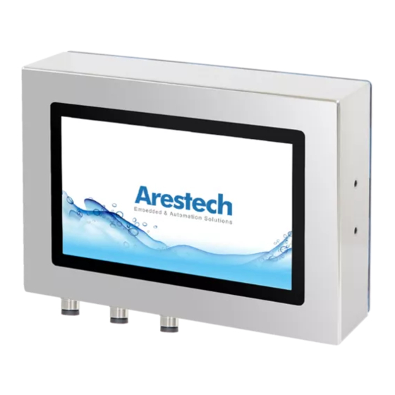
- Page 1 User Manual User Manual TPM-3610PW Full System IP66/69K Protected 10.1" Stainless Steel Industrial Monitor with Capacitive Touch, Bedienfront Monitore...
- Page 2 User Manual Record of Revision Version Issued Date Description Owner v0.1 2021.3.17 First Release Derek...
- Page 3 Arestech’s high quality-control standards and rigorous testing, most of our customers never need to use our repair service. If an Arestech product is defective, it will be repaired or replaced at no charge during the warranty period. For outof- warranty repairs, you will be billed according to the cost of replacement materials, service time and freight.
- Page 4 User Manual If your product is diagnosed as defective, obtain an RMA (return merchandize authorization) number from your dealer. This allows us to process your return more quickly. Carefully pack the defective product, a fully-completed Repair and Replacement Order Card and a photocopy proof of purchase date (such as your sales receipt) in a shippable container.
- Page 5 User Manual Liquid has penetrated into the equipment. The equipment has been exposed to moisture. The equipment does not work well, or you cannot get it to work according to the user's manual. The equipment has been dropped and damaged. ...
-
Page 6: Table Of Contents
User Manual Contents Chapter 1: General Introduction..................1 1.1 I/O Arrangement................1 1.2 OSD Key Use instructions............5 1.3 Mechanical Dimension..............7 Chapter 2: VESA Mounting..................8 2.1 VESA Mounting................8 2.2 Yoke Mounting................9 2.3 Wall Mounting................10 Chapter3. System Setup................11 3.1 Power Installation Procedure..............11 1 Main Menu .......... -
Page 7: Chapter 1: General Introduction
User Manual 1.1 I/O Arrangement Capacitive IO Page 1... - Page 8 User Manual VGA M12 Port Famale 12pin Definition Definition RED Gnd BLUE GREEN GND GREEN BLUE GND 12 M12 USB Port Male 5pin Definition SHILDING * Only Touch control Use Page 2...
- Page 9 User Manual M12 12/24V DC IN Female 5pin Definition Touch On/Off Botton LIGHT Stauts Green ON ->ACTIVE No light OFF->NO ACTIVE Pressure Relief Valve Quickly discharge moisture and pressure, keep the internal pressure of the machine balanced, and effectively prevent the invasion of water and dust Page 3...
-
Page 10: Osd Key Use Instructions
User Manual 1.2 OSD Key Use instructions Power Key: LCD power key LED lights: two-color LED (ON->Green/OFF-->Red) Key: increase the brightness of the keys; Menu key for Up Key: decrease the brightness keys; Menu key for Down ... - Page 11 User Manual OSD Menu Description Color Adjustment Contrast 0~100 Brightness 0~100 ColorAdjustment Red (0~100) Green (0~100) Blue (0~100 Color Temperature 9300K 6500K User Image Adjustment Clock Phase Sharpness 0~100 horizontal position 0~100 Vertical Position 0~100 OSD Menu OSD Horizontal Pos 0~100 OSD Vertical Pos 0~100...
- Page 12 User Manual Singnal Source D-SUB HDMI Display Port Auto Search Audio Volume 0~255 (Recommended to 150 ) Mute Page 6...
-
Page 13: Mechanical Dimension
User Manual 1.3 Mechanical Dimension Page 7... -
Page 14: Chapter 2: Vesa Mounting
User Manual Chapter 2. VESA / Panel Mounting 2.1 VESA Mounting Step1. Check the VASA mount dimension on the back cover . There are two choice : 100 x 100mm or 75 x 75 mm 1. Screw Length Limitation: 6mm (Calculated from monitor's back cover) 2. -
Page 15: Yoke Mounting
User Manual 2.2 Yoke mounting 1.Follow the screw M6 hole of the yoke mount to fix.According to the following opening size 2.First fix the screw PPC and yoke mount,the screw is M6 size 3.Then fix the angle of the screw, the angle is 15 degrees,the screw is M6 size Page 9... -
Page 16: Wall Mounting
User Manual 2.3 Wall mounting 1.Follow the screw M6 hole of the wall mount to fix.According to the following opening size 2.First fix the screw PPC and wall mount,the screw is M6 size 3.Then fix the angle of the screw, the angle is 15 degrees,the screw is M6 size Page 10... -
Page 17: Chapter3. System Setup
User Manual Chapter3. System Setup 3.1 Power Installation Procedure Step 1. Connect the Power M12 Connector and tighten in a clockwise direction AC to DC power adaptor specification 1. Input support voltage: 110V ~ 240V AC power , 50~60Hz 2. Output support voltage: 12V DC power @5A MAX 3. - Page 18 User Manual 7F., No.94, Xiwei St., Sanchong Dist., New Taipei City 241, Taiwan (R.O.C.) Tel : 886-2-8287-9168 Fax : 886-2-8287-2577 www.arestech.com.tw Page 12...
Need help?
Do you have a question about the TPM-3610PW and is the answer not in the manual?
Questions and answers