Advertisement
January 2006
INSTALLATION & SERVICE
INSTRUCTIONS
FOR
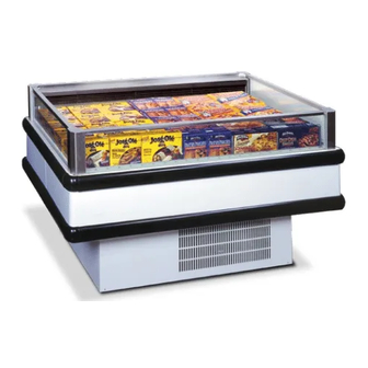
ISF
Island Spot Low or Medium Temperature
Remote and Self Contained Merchandisers
First Call for help (US and Canada):
1-800-922-1919
Soporte Tècnico y Asistencia (Mèxico):
01-800-522-1900
For a Service Network Locator and other
Information visit us at
www.hussmann.com
select Worldwide Locations
P/N OII – ISF Merchandiser
January 2006
HUSSMANN - GLOVERSVILLE
Advertisement
Table of Contents

Subscribe to Our Youtube Channel
Related Manuals for Hussmann ISFGG


Summary of Contents for Hussmann ISFGG
- Page 1 Remote and Self Contained Merchandisers First Call for help (US and Canada): 1-800-922-1919 Soporte Tècnico y Asistencia (Mèxico): 01-800-522-1900 For a Service Network Locator and other Information visit us at www.hussmann.com select Worldwide Locations P/N OII – ISF Merchandiser January 2006 HUSSMANN - GLOVERSVILLE...
-
Page 2: Table Of Contents
TABLE OF CONTENTS SECTION 1 SECTION 2 SECTION 3 SECTION 4 SECTION 5 SECTION 6 SECTION 7 SECTION 8 GENERAL INFORMATION INSTALLATION REFRIGERATION Self Contained Models REFRIGERATION Remote Models ELECTRICAL REPLACEMENT PARTS LIST USER INSTRUCTIONS SERVICE TIPS PAGE 3 PAGE 4 PAGE 7 PAGE 9 PAGE 18... -
Page 3: General Information
(frozen food) or Medium temperature (fresh meat, dairy, and delicatessen models). The ISFGG will have upper glass on 4 sides. The ISMGG model has been designed for medium temperature operation and it will have the upper glass installed on all four sides. The ISFRGG will have curved glass on all sides. -
Page 4: Installation
Page 4 SECTION 2 INSTALLATION SHIPPING DAMAGE All equipment should be thoroughly examined for shipping damage before and during unloading. This equipment has been carefully inspected at our factory and the carrier has assumed responsibility for safe arrival. If damaged, either apparent or concealed, a claim must be made to the carrier. -
Page 5: Waste Outlet And Water Seal
LEVELING The refrigerator must be level to insure proper operation of the refrigeration system and to insure proper drainage of defrost water. Use the leveling shims provided to level the case with the aid of a carpenter’s level. Leveling must be performed from front-to-back and from side-to- side. - Page 6 Page 6...
- Page 7 ALL LOWER BASE PANELS MUST BE IN PLACE WHEN THE REFRIGERATOR IS OPERATING. IF NOT, AIRFLOW FROM THE CONDENSER WILL BE DIRECTED OVER THE EVAPORATOR PAN AND DEFROST WATER IN THE PAN MAY OVERFLOW. REFRIGERANT CHARGE MODEL REFRIGERANT ISFGG/RGG-5 ISMGG/RGG-5 ISMGG/RGG-10 ISFGG/RGG-10 ISCGG-5 SECTION 3...
-
Page 8: Refrigeration
CONTROLS and ADJUSTMENTS REFRIGERATION CONTROLS LOW TEMP (FROZEN FOOD) ISFGG/ MEDIUM TEMP (DAIRY, DELI) DUALTEMP LOW TEMP ISCGG (ICE CREAM) MEDIUM TEMP ISMGG/ (DAIRY, DELI) A refrigeration thermostat controls refrigeration temperature. This is factory installed in the control panel. Adjust this thermostat to maintain the discharge air temperature shown. -
Page 9: Remote Models
Refrigerant lines should be sized as shown on the refrigeration legend prepared for the store and as (furnished by the owner). If a legend has not been furnished, refer to Section 12 of the Hussmann Application Engineering Manual for guidance. OIL TRAPS P-traps (oil traps) must be installed at the base of all suction line vertical risers. -
Page 10: Expansion Valve Adjustment
PIPING INSULATION For refrigerators with other than KOOLGAS defrost, the suction and liquid lines should be clamped and/or taped together and insulated for a minimum of 30 feet from the refrigerator. Refrigerators with KOOLGAS defrost should not have their liquid and suction lines in contact with each other but are to be separately insulated for a minimum of 30 feet from the refrigerator. - Page 11 A pump down system is recommended for outdoor condensing units. DEFROST: ISFGG / RGG, models have electrical defrost and are time initiated with pressure termination. For Koolgas application, a Klixon sensor is mounted on the coil to provide a temperature termination control signal.
- Page 12 - 20 F -35 F ISCGG (Ice Cream) MedTemp +24 F ISFGG/ (Dairy Deli) MedTemp +24 F ISMGG/ (Dairy Deli) Discharge air temperature is to be measured by attaching a service thermometer to the discharge honeycomb at the centre of the case.
- Page 13 Electric defrost is time initiated and temperature terminated. Termination is initiated by a “close-on-rise” Klixon sensor mounted on an evaporator tube. “Off-time” defrost is time initiated and time terminated. REFRIGERATION CONTROLS Low Temp (Frozen Food) ISFGG-R Medium Temp (Dairy, Deli) ISMGG- Medium Temp (Dairy, Deli) Discharge air temperature is to be measured by attaching a service thermometer to the discharge honeycomb at the centre of the case.
- Page 14 Page 14 REMOTE CONTROL KIT (Optional) The control settings listed in the preceding tables are those that will provide proper case performance. If these spot display refrigerators are to be multiplexed with different types of refrigerator models, we suggest that each spot display refrigerator be equipped with a “REMOTE CONTROL KIT”. The remote control kit will insure better control of refrigeration temperature and provide additional defrost controls that maybe needed since most other refrigerators do not have similar defrost frequencies and terminations (fail safeguards) with these spot display refrigerators.
- Page 15 DESCRIPTION Liquid Line Solenoid Valve Refrigeration Thermostat On / Off Switch Defrost Timer HUSSMANN PART # 04-S-067 03-S-286 03-S-269 MANUFACT. PART # Sporlan A351 or B651 White Rogers 1710-4 Cutler Hammer 7599K1 Paragon 8045-0B...
- Page 16 DESCRIPTION Liquid Line Solenoid Valve Refrigeration Thermostat Disconnect Switch Defrost Timer HUSSMANN PART. # Sporlan A351 or B651 04-S-067 White Rogers 1710-4 03-S-286 Various “2PST” 03-S-269 Paragon 8045-0B MANUFACT. PART #...
-
Page 17: Self Contained Models
ELECTRICAL CONNECTIONS Electrical power connections are made at the left-hand end of the case, behind the removable base panel. The left-hand end of the case is determined when facing the discharge honeycomb. REMOTE MODELS All electrical connections for remote models will be made in the junction box located behind the removable base panel, at the left-hand end of the case. - Page 18 SERIAL PLATE AMPERAGES Serial plate amperes are the amperage figures that are stamped on the fixture’s Serial Plate. Although all field-installed wiring must be sized to the Serial Plate amperages, the actual current or amps may be less than specified. (Serial Plate is located on panel of the product display area.) SELF CONTAINED MODELS MODEL ISM / G / G –...
-
Page 19: Replacement Parts List
REPLACEMENT PARTS LIST: ISF MODELS ITEM # HUSSMANN PART # 380057 21-S-139 136260 21-S-133 375026 920057 19-S-758 302720 19-S-751 380064 261933 04-S-067 294226 03-S-286 047449 03-S-559 059995 297179 21-S-141 118395 21-S-140 380061 17-S-533 380062 035774 17-S-186 380063 17-S-551 SECTION 6... - Page 20 REPLACEMENT PARTS LIST: ISF MODELS ITEM # HUSSMANN PART # Continued: ISF- R, ISFG- R, ISFGG-R, 380024 2-S-628 112033 25-S-114 314580 314573 NOTE: Items 1 through 6 are standard parts for both the remote and Items 7 through 20 are standard parts for only the...
- Page 21 REPLACEMENT PARTS LIST: ISMG – 5R & ISMG - 5B ITEM # HUSSMANN PART # 380057 21-S-139 136260 21-S-133 315799 19-S-752 381652 17-S-390 261933 04-S-067 294226 03-S-286 047449 03-S-559 059995 205238 379522 380099 02-S-629 314580 314573 838506 838947 209097 SECTION 6...
- Page 22 REPLACEMENT PARTS LIST: ISF – K & ISFG – K ITEM # HUSSMANN PART # 380057 21-S-139 136260 21-S-133 375026 920057 19-S-758 322013 380064 261933 04-S-067 000582 106236 03-S-560 205534 297179 21-S-144 118395 21-S-140 380061 17-S-533 380062 035774 17-S-186 380063...
- Page 23 ISFG-D, 381616 02-S-638 112033 25-S-114 314580 322013 SECTION 6 DESCRIPTION ISFG- K ISFGG-D ISFGG-K Compressor - Copeland # KAMA – 0075 – TAC - 299 Condenser – HeatCraft Inc. 0271099B00J High Pressure Control TI # 26PSXXX WC400 K32-K Heater, Condensate...
- Page 24 ISMGG - 8 ISMGG - 10 920057 ISFG - 5 920057 ISFG - 8 857853 19-S-773 ISFG - 10 920057 (x2) ISFGG - 5 920057 ISFGG - 8 857853 ISFGG - 10 920057 (x2) HEATER LOCATION SIDE GLASS FRONT/REAR GLASS 375030...
-
Page 25: User Instructions
USER’S INSTRUCTIONS STOCKING Merchandise should not be placed in the refrigerator until it is at the designed operating temperature, approximately 2-3 hours. When stocking, never allow product to extend beyond the “Load Limit” decals affixed to ht exterior of the refrigerator. AIR DISCHARGE AND RETURN AIR FLUES MUST BE UNOBSTRUCTED AT ALL TIMES TO PROVIDE PROPER REFRIGERATION AND AIR CURTAIN PERFORMANCE. - Page 26 CARE AND CLEANING CONTINUED WHEN CLEANING: CONNECT THIS TUBE TO A REMOTE HOSE TO CARRY WATER AWAY. BE SURE TO CRIMP AND RE-INSERT THE TUBE BACK INTO ITS HOLDING CLIPON THE EVAPORATOR PAN, OR PLACE DRAIN TUBE BACK INTO THE EVAPORATOR PAN AFTER CLEANING.
-
Page 27: Service Tips
SERVICE TIPS ALWAYS DISCONNECT THE ELECTRICAL POWER AT THE MAIN DISCONNECT AND OBSERVE ALL ELECTRICAL LOCKOUT PROCEDURES, WHEN SERVICING OR REPLACING ANY ELECTRICAL COMPONENT OF THIS REFRIGERATOR. THIS INCLUDES, BUT IS NOT LIMITED TO SUCH ITEMS AS FANS AND THERMOSTATS. FAN BLADE REPLACEMENT The evaporator fan is located at the centre of the case directly beneath the display pan. - Page 28 Page 28 ANTI-SWEAT HEATERS The anti-sweat heaters are located along the lower glass perimeter and inside the nose discharge panel. Servicing the anti-sweat heaters requires removal of the corner caps, then the glass or nose discharge panel. To remove corner caps simply hold part and pull upwards. Corner caps naturally fit tight to prevent undesirable removal.
- Page 29 CONDENSATE PAN HEATER TIMER ELECTRICAL BOX 208/230/125 V NOTE: USE COPPER,COPPER CLAD, OR ALUMINUM 60 Hz CONDUCTORS ONLY. 1 Ph SPECIAL FOR ISFGG-5D/G & 10D/G W/DUAL TEMP KIT EVAPORATOR CONDENSER LOW TEMP MED TEMP THERMOSTAT THERMOSTAT BLUE BLUE PURPLE BLUE...
- Page 30 HARNESS DISCONNECT DISCHARGE NOSING ANTI-SWEAT HEATER CONDENSATE PAN HEATER TIMER ELECTRICAL BOX NOTE: USE COPPER,COPPER CLAD, OR ALUMINUM CONDUCTORS ONLY. EVAPORATOR 3/4 HP COMPRESSOR MOTOR THERMOSTAT BLUE BLUE HIGH PRESSURE SAFETY CONTROL CONTACTOR BLACK 120 V 60 Hz GROUND 1 Ph WHITE CURRENT RELAY USAGE: ISMG/GG-5B &10B...
- Page 31 APPROVED BY EO NUMBER -REV A REROUTED WIRES TO CORRESPOND W/ SUB-ASSY 5291-REV A DRAWN BY: SCALE INCHES DATE DRAWN : XX/XX/2001 SHEET # 1 OF 1 APPROVED BY: POTENTIAL RELAY YELLOW CAPACITOR GLOVERSVILLE, NY 12078 WIRING DIAGRAM-ISFGG-5B M100-2277 A...
- Page 32 FRONT/SIDE GLASS ANTI-SWEAT HEATER DISCHARGE NOSING ANTI-SWEAT HEATER CONDENSATE PAN HEATER TIMER ELECTRICAL BOX NOTE: USE COPPER,COPPER CLAD, OR ALUMINUM CONDUCTORS ONLY. SPECIAL FOR ISFGG-5B & 10B W/DUAL TEMP KIT DEFROST HEATER CONDENSER LOW TEMP MED TEMP THERMOSTAT THERMOSTAT BLUE BLUE...
- Page 33 USAGE: ISFG/GG-5 D/G & 10D/G PWR SWITCH ISCG/GG-5 D/G TOLERANCES UNLESS OTHERWISE SPECIFIED: FRACTIONAL 1/32" DECIMAL 0.031" ANGULAR 1° HOLE LOCATION & SPACING 1/64" EO NUMBER WIRING DIAGRAM-ISFGG-5 & 10 D/G DRAWN BY: SCALE INCHES DATE DRAWN : XX/XX/2001 SHEET #...
Need help?
Do you have a question about the ISFGG and is the answer not in the manual?
Questions and answers