Advertisement
Quick Links
1
DC/AC coupling and OFFSET VOLTAGE ISSUES
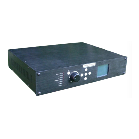
Ultimate-Preamplifer
by
Analog-Precision
http://www.analog-precision.com/
DC/AC COUPLING AND OFFSET VOLTAGE
ISSUES
1 |
P a g e
Copyright © 2018 by Analog-Precision. All Rights Reserved
http://www.analog-precision.com
Tuesday, June 05, 2018
Advertisement

Related Manuals for Analog-Precision Ultimate-Preamplifer

Summary of Contents for Analog-Precision Ultimate-Preamplifer
- Page 1 DC/AC coupling and OFFSET VOLTAGE ISSUES Ultimate-Preamplifer Analog-Precision http://www.analog-precision.com/ DC/AC COUPLING AND OFFSET VOLTAGE ISSUES P a g e Copyright © 2018 by Analog-Precision. All Rights Reserved http://www.analog-precision.com Tuesday, June 05, 2018...
- Page 2 As can be see in the following DC measurement the DC offset between balanced output pins 2-3 on the Channel-1 XLR connector with the DC coupling jumpers in place is of the order of 23 mV. P a g e Copyright © 2018 by Analog-Precision. All Rights Reserved http://www.analog-precision.com Tuesday, June 05, 2018...
- Page 3 1 & 2 and pins 2 & 3 is of the order of 1.6 Volts which is nearly a hundred times as much as the differential offset voltage. P a g e Copyright © 2018 by Analog-Precision. All Rights Reserved http://www.analog-precision.com Tuesday, June 05, 2018...
- Page 4 Likewise, for AC coupling you should remove the jumpers. As each channel has its own individual jumper you can customize each channel depending on the amplifier it is connected to. P a g e Copyright © 2018 by Analog-Precision. All Rights Reserved http://www.analog-precision.com Tuesday, June 05, 2018...
- Page 5 To remove the Unbalanced board, first remove all of the IDC connectors connected to both the Unbalanced and Balanced boards as in the following image. P a g e Copyright © 2018 by Analog-Precision. All Rights Reserved http://www.analog-precision.com Tuesday, June 05, 2018...
- Page 6 Next you will have to gently remove the 8 retaining nuts and washers on the RCA jacks using a 16 mm extended socket. P a g e Copyright © 2018 by Analog-Precision. All Rights Reserved http://www.analog-precision.com Tuesday, June 05, 2018...
- Page 7 Do this for each channel that you want to configure. P a g e Copyright © 2018 by Analog-Precision. All Rights Reserved http://www.analog-precision.com Tuesday, June 05, 2018...
- Page 8 Power up the unit and measure the offset at the output. If the unit is AC coupled (ie jumpers removed) you should see there is no longer any DC offset at the output of the XLR connector. P a g e Copyright © 2018 by Analog-Precision. All Rights Reserved http://www.analog-precision.com Tuesday, June 05, 2018...
- Page 9 DC/AC coupling and OFFSET VOLTAGE ISSUES Pins 1 and 2 DC measurement. Pins 1 and 3 DC measurement. P a g e Copyright © 2018 by Analog-Precision. All Rights Reserved http://www.analog-precision.com Tuesday, June 05, 2018...
Need help?
Do you have a question about the Ultimate-Preamplifer and is the answer not in the manual?
Questions and answers