Advertisement
Quick Links
Advertisement

Related Manuals for Correlated Solutions Vic-Gauge 3D


Summary of Contents for Correlated Solutions Vic-Gauge 3D
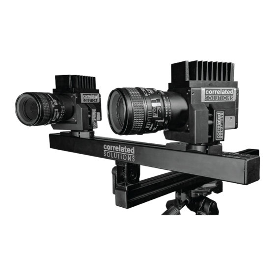
- Page 1 Vic-Gauge 3D T e s t i n g G u i d e www.correlatedsolutions.com...
- Page 2 For any test where excessive heat, shock, or flying debris may be present, take steps to protect the cameras and equipment. Various shielding solutions are available – please contact Correlated Solutions for more details.
- Page 3 Introduction This guide explains the basic steps in running a Vic-Gauge 3D test, from start to finish. A typical sequence will be: Preparing the specimen Setting up, pointing, and focusing the cameras on the specimen Calibrating the camera system ...
-
Page 4: Setting Up The Cameras
Setting up the cameras Pointing the cameras To begin, set your prepared specimen in its testing location. Be aware of the orientation and potential camera placement; for example, for a dog-bone specimen in a test frame, the prepared face of the specimen should face outwards from the test frame rather than facing the frame‟s columns. - Page 5 The cameras are shown side by side; you can also view an individual image by selecting the tab for a given camera. The red areas in each image indicate overdrive/saturation, where the pixel is driven to its highest possible brightness value. The images can be zoomed by placing the mouse over an image and using the scroll wheel.
- Page 6 The distance is set so that the specimen fully fits in the field of view, while being close enough to get a good image and use much of the camera‟s resolution. Note that the field of view should be set with consideration to the final size and position of the specimen. Here, because we expect axial tension, we‟ve allowed room for the specimen to strain.
- Page 7 Adjusting focus When the cameras have been positioned, the next step will be to set focus. Use the focus control on your lenses to achieve a sharp focus on the entire specimen. Often, it will be helpful to zoom in on the image to check fine focus; with high resolution cameras, a slight defocus will not be visible with the image zoomed out to fit on screen.
- Page 8 Aperture and exposure time As you make the image sharp through the focus adjustment, it will also be necessary to adjust the brightness of the image. There are two controls available for this: the aperture/iris setting on the lens, and the exposure time setting of the camera. ...
- Page 9 This lens has a focus and aperture ring, each with locking knob. The aperture ring is normally closest to the camera. Loosen the locking knob (if present); make any adjustments; and tighten the lock before calibrating. This lens has an aperture ring with a locking knob.
- Page 10 For many moderately sized specimens, a simple task lamp of 50-100 watts will give excellent light levels while providing diffuse, even illumination. For very small specimens at high magnification, a fiber optic illuminator can be used. For very large specimens, a 300-500 watt halogen light or a specialized machine vision lighting solution may be required.
- Page 11 Calibration Once the focus, aperture, and camera position are set, the system must be calibrated. Selecting a grid To begin, select a grid that approximately fills the field of view. Slightly too small Correct Too large If the grid is too small, it may be difficult for Vic-Gauge to automatically extract points; additionally, more total images will be required to cover the field of view, including the corners.
- Page 12 vibration and shock compared to dragging the tripod away. Then, calibrate to the left or right of the specimen position before returning the rig to center. If the tripod must be moved, it may be helpful to mark the original location of each leg; otherwise, finding the original rotation and position may be difficult.
- Page 13 Computing Calibration To calibrate using the acquired grid images, select the Calibration tab at the toolbar to the right. Use the Grid pulldown to select the grid you used – in our case, a 9mm grid. Then, click Analyze. The points will be automatically extracted from each image, and a calibration computed.
- Page 14 Each image is displayed with an error score, and a final error score is displayed at the bottom. Lower scores are better; any scores displayed in red are marginal or too high. Selecting distortion order Distortion order can be chosen using the spin box at the bottom of the dialog. For lenses with higher distortion orders, more images may be required, and it becomes even more important to take grid images where points are present in the corners of the field of view.
- Page 15 Center (x,y): the position on the sensor where the lens is centered. It should be roughly in the physical center of the sensor. The confidence intervals for center (x) and (y) will generally be higher for long- focal-length lenses. At very small fields of view and high magnification lenses (70mm and up), the interval may be higher in magnitude than the value itself –...
- Page 16 Placing gauges Once the cameras are set up, you can place one or more virtual gauges on the specimen. To place a gauge, right-click in the camera 0 (left) image, and click Add gauge here. A virtual gauge will appear on the surface. The gauge has three yellow nodes that can be dragged.
- Page 17 To change the size of the gauge, click and drag the node at the lower right: Larger gauges will compute more slowly and average over a larger area. Using a larger gauge can also give much more accurate strain results especially when strains are small. To move the gauge itself, click and drag the center node.
- Page 18 To create a virtual extensometer, click and drag on the center of one gauge. Drag the gauge on top of another gauge; a line will appear. Release the mouse button to complete the extensometer. A virtual gauge measures a position (X, Y, Z), a displacement (U, V, W), and a strain tensor (strain in X, strain in Y, shear strain).
- Page 19 The reference image Once all gauges have been placed, you can select a reference image. This image defines the reference state of the object; all deformations and strains will be relative to this image. To select this image, click the Reference icon in the toolbar. Vic-Gauge will attempt to place the gauges in the camera 1 (right) image in the matching positions.
- Page 20 Analog connections and setup If a data acquisition device is connected, you can configure analog inputs and outputs. To start, select the Controls tab at the right. You may configure up to two voltage outputs to produce a voltage proportional to one of your strain measures.
- Page 21 You can also select an analog input to monitor. Pull down to select the channel, or click Edit to edit labels and scales. Each channel can have a range; title (for your reference); factor (i.e., 2000 for a 2000lb/volt load cell); and an offset. Click Zero to set the offset to the current value, zeroing the value.
-
Page 22: Running The Test
Running the test Once you have calibrated, placed gauges, selected a reference image, checked your gauges for correct initial positioning, and set up your analog inputs/outputs, you can begin testing. Before starting, you can click Save Project in the toolbar, and select a filename. - Page 23 The calculated values are plotted in the Plots tab at the right. To edit a plot, you can right-click in the plot area: Various values are available for plotting including displacement (top plot) and strain (bottom plot). Note that here, we plot e1 (major strain) in the bottom plot;...
- Page 24 Full-field Analysis Vic-Gauge 3D is a useful tool for retrieving pointwise strain data in real time. In many cases, it will also be necessary to retrieve full-field 3D data. In this case, you will need to save full-field TIFF images just as with a normal Vic-Snap/Vic-3D test.
- Page 25 STEREO CAMERA MOUNTING INSTRUCTIONS Items List: A. Tripod B. Tripod 3-axis adjustable head C. Tripod quick-release adapter D. Slide block E. 23” Aluminum profiles F. Adjustable extrusion mounting hinge G. Camera FLEX mounts H. Extrusion profile end caps Tools required: I.
- Page 26 Figure 1. Items List Set up tripod a. Pull the three legs outward to the desired location b. Unlatch each leg and raise to the approximate desired height c. Lock them back so the tripod is stable.
- Page 27 Figure 2. Tripod There is an option whether to incorporate the tripod 3-axis adjustable head in the setup. The tripod head allows for additional degrees of freedom and more adjustability. However, the more degrees of freedom that are present in the system, the less rigid the system is.
- Page 28 Screw the tripod 3-axis head onto the tripod. Make sure the handles are attached. Figure 3. Trip with 3-axis head/bracket assembly Snap the quick-release bracket to the tripod 3-axis adjustable head. Figure 4: Quick-release bracket...
- Page 29 a. To fasten the slide block to the tripod 3-axis adjustable head, verify that there is a helical insert present in the slide block. This will allow the slide block to screw directly onto the tripod head. Figure 5. Slide block with helical insert Screw the slide block onto the tripod 3-axis adjustable head.
- Page 30 Figure 7. Slide block without helical insert Figure 8. Slide block mounted to tripod Carefully slide one of the 23” aluminum extrusion pieces into the slide block about halfway (the handle/T-nut may need to be loosened in order to be to do this), and then hand tighten the handle on the side of the block to fasten the extrusion in place.
- Page 31 Figure 9. Aluminum extrusion on slide block Attaching the hinge a. Loosen the T-nuts on the mounting hinge so that they will slide into the slots of the extrusion. Orient it so that the silver inserts on the hinge go through the slot of the extrusion.
- Page 32 Figure 10. Hinge mounted to extrusion c. Tighten the T-nut with the provided 5mm hex driver so that the hinge is close to the end of the extrusion. d. Slide the other 23” extrusion piece through the hinge‟s other T-nut about halfway so that it is perpendicular to the already mounted extrusion bar, as seen in Figure 11.
- Page 33 Figure 11. Hinge attaches aluminum extrusions Attaching the camera/swivel mounting assembly a. Each swivel mount has two T-nut fasteners. b. Loosen the T-nuts so that they will slide into the slot of the extrusion. c. Slide the swivel camera mounts to the desired position on the extrusion bar.
- Page 34 Figure 12. Mounting the camera/swivel assembly Attach the 4 end caps to the aluminum extrusion ends.
- Page 35 Figure 13. Attach all four end caps Adjust all degrees of freedom to the desired locations and tighten. Other mounting configurations are shown in Figures 14 and 15. Figure 14 displays the final configuration when the tripod head is omitted. Figure 15 shows a configuration in which the cameras are mounted vertically (by mounting the hinge on a different surface of the aluminum extrusion).
- Page 36 Figure 14. Complete system with omitting tripod head Figure 15. Complete system with vertical camera mounting...
- Page 37 CSI Application Note AN-525 Speckle Pattern Fundamentals Introduction The digital image correlation technique relies on a contrasting pattern on the surface of the test specimen. This pattern can be painted; naturally occurring; or even projected on the surface, but a few tips will help to give the best pattern and the best results. Pattern Requirements To achieve effective correlation, our pattern must be ...
- Page 38 Pattern Scale In addition to the above requirements, speckles should be neither too small nor too large. In practice, there is a very wide range in how large a speckle pattern may be, and still achieve excellent results, but having an optimal pattern will give the best flexibility. To understand what makes an optimal pattern, a bit of background on the theory will be helpful.
- Page 39 Conversely, if the pattern is too small, the resolution of the camera may not be enough to accurately represent the specimen; in information terms, we can call this aliasing. Instead of appearing to move smoothly as the specimen moves, the pattern will show jitter as it interacts with the sensor pixels;...
- Page 40 In addition, patterns that are too fine are very sensitive to defocus – out of focus regions may simply become gray. In general, speckles should be at least 3-4 pixels in size to avoid these issues. Put another way, speckles should be visible as distinct features, as opposed to random „salt and pepper‟...
- Page 41 Techniques Spray paint The most common technique for applying a speckle pattern is with ordinary paint. Paint can be used with any intermediate-sized specimen that will not be chemically affected by the paint, nor stiffened by it. This is usually the best choice for metal, ceramic, and composite specimens from ~1”...
- Page 42 Toner For very small specimens, a very fine pattern can be applied with toner powder. This method works well for specimens smaller than ½” (12mm). For this technique, the specimen should be coated white. Then, toner powder can be blown with a small lens blower, or by mouth, onto the surface.
- Page 43 Stencils For very large specimens, a stencil can be used to roll or spray a perfect speckle pattern. Stencils can be made from thin vinyl with water or laser cutting techniques. The pattern below was applied to a 16‟ (5m) panel. While this pattern appears somewhat regular, which violates our „random‟...
- Page 44 For some specimens, ink – placed with a marker – is a good technique. This technique affects the surface minimally, and allows measurement of very high strain. The ink can simply be dotted onto the surface with a marker. This technique can be very time consuming for larger specimens.
- Page 45 Inherent patterns Some materials such as wood or concrete display an inherent pattern. These patterns may be used for correlation if they have sufficient contrast, although an applied pattern is still usually optimal. Textures Some specimens exhibit an apparent speckle pattern due to an inherent texture; examples include sand, rough metal, and concrete.
Need help?
Do you have a question about the Vic-Gauge 3D and is the answer not in the manual?
Questions and answers