Advertisement
Quick Links
TRANSISTOR TESTER
CONTENTS:
Section 1: General and Planning Information
Section 2: Components and Material Required
Section 3: Assembly
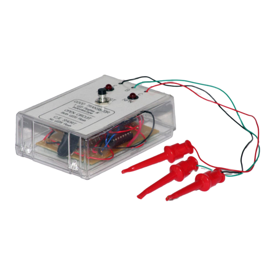
DESCRIPTION
This device is used to detect a faulty
transistor, within an assembled PCB.
The testing can be carried out on the
PCB's components, so that only the
faulty transistor needs to be removed
and replaced. The
PCB and components are small
enough to fit into a small plastic box,
making it very portable.
SECTION 1:
1. DESIGN CONSIDERATIONS
1.1 GENERAL
Locating a faulty transistor on a circuit board, crowded with soldered in place
components, can be a difficult proposition. With an in-circuit
however, the component's general quality can be determined, while avoiding damage
to other components and/or the foil pattern, due to excessive soldering iron heat. The
TRANSISTOR TESTER
faulty and, as bonus, tell you the component's type (PNP or NPN).
A pair of flashing LED's indicates the transistor's condition. One LED flashes if the
transistor is a functional PNP type, while the other LED flashes if the transistor is a
good NPN type. If the transistor is faulty, either both LEDs will flash or neither will
flash, depending on the type of failure.
SECTION 2: COMPONENTS & MATERIAL REQUIRED
2.1 COMPONENTS SUPPLIED
The following components are supplied in the kit:
SCORPIO TECHNOLOGY
17 Inverell Ave., Mt. Waverley, Vic. 3149
Revised: 11 September 2015 www.scorpiotechnology.com.au
Issued: 17 February 2013
sales@scorpiotechnology.com.au
TRANSISTOR TESTER
GENERAL AND PLANNING INFORMATION
described here will indicate whether a suspect transistor is good or
www.scorpiotechnology.com.au
Section 4: Wiring
Section 5; Testing
Section 6: Theory – How the Circuit Works
VICTORIA PTY. LTD.
A.B.N. 34 056 661 422
Tel: (03) 9802 9913
1
TRANSISTOR TESTER
ax: (03) 9887 8158
F
sales@scorpiotechnology.com.au
,
Advertisement

Related Manuals for SCORPIO TECHNOLOGY TRANSISTOR TESTER

Summary of Contents for SCORPIO TECHNOLOGY TRANSISTOR TESTER
- Page 1 TRANSISTOR TESTER CONTENTS: Section 1: General and Planning Information Section 4: Wiring Section 2: Components and Material Required Section 5; Testing Section 6: Theory – How the Circuit Works Section 3: Assembly DESCRIPTION This device is used to detect a faulty transistor, within an assembled PCB.
- Page 2 (as per the PCB and instructions). Incorrect orientation of components will cause TRANSISTOR TESTER malfunction. It may also cause damage to some components. Mount the resistors (R1 to R5). Use the colour coded bands to identify each resistor.
- Page 3 Mount the diodes (D1 to D4): these have a glass body, with a black band near one end to identify the negative end. Make sure the ends with the bands around them are placed in the same direction as shown on the diagram. ...
- Page 4 Solder the wires from the PCB to the pushbutton switch. Fit the pushbutton switch into position on the cover, in the hole marked "Test". WARNING: Take care when soldering the wires to the switch terminals - overheating can damage the plastic body of the switch. ...
- Page 5 TESTER. NOTE: One of each transistor type - i.e. an NPN and a PNP - should be used to test your TRANSISTOR TESTER . If you have a known faulty transistor available, it also can be used. 5.1 TESTING ...
- Page 6 input frequency by two, but more importantly, delivers complementary voltage outputs at pins 15 of 1C1 (Q) and 14 (not-Q). These complementary outputs are connected to indicators LED1 and LED2 via current- limiting resistor R3. The LED's are arranged so that when the polarity across the circuit is one way, only one LED will be illuminated, and when the polarity is the reverse of that, the other LED is illuminated.
Need help?
Do you have a question about the TRANSISTOR TESTER and is the answer not in the manual?
Questions and answers